SucceX-Force 5.8G25mW/100mW/400mW/800mW
Wiring Diagram
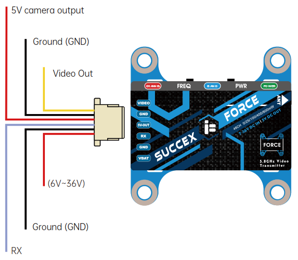
 5V Output only for FPV cameras!
- The RX wire can be linked to any free UART TX on your Flight Control and setup for IRC Tramp VTX telemetry to change parameters of your VTX through your OSD.
- If you experience severe signal interference in your video feed please inspect your power source for electrical noise. Some common issues are too long motor screws, no additional capacitor added to your ESC, bad or noisy motors, bad or noisy ESC.
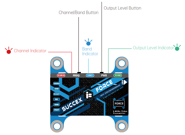
Power Level SelectionLong Press for 2 seconds to select Power Level
| Power | PIT | 25mW | 100mW | 400mW | 800mW |
| Green LED | light ON | Flash 1x | Flash 2x | Flash 3x | Flash 4x |
Band SelectionLong Press for 3 seconds to enter Band selection
| Group | BAND A | BAND B | BAND E | BAND F | RaceBand | LowRace |
| Blue LED | Flash 1x | Flash 2x | Flash 3x | Flash 4x | Flash 5x | Flash 6x |
Channel SelectionShort Press to enter the Channel selection
| Group | CH1 | CH2 | CH3 | CH4 | CH5 | CH6 | CH7 | CH8 |
| Red LED | Flash 1x | Flash 2x | Flash 3x | Flash 4x | Flash 5x | Flash 6x | Flash 7x | Flash 8x |
RF Frequency Table
|
BAND |
CHANNEL |
|||||||
|
CH1 |
CH2 | CH3 | CH4 | CH5 | CH6 | CH7 |
CH8 |
|
| A | 5865M | 5845M | 5825M | 5805M | 5785M | 5765M | 5745M | 5725M |
| B | 5733M | 5752M | 5771M | 5790M | 5809M | 5828M | 5847M | 5866M |
| E | 5705M | 5685M | 5665M | 5645M | 5885M | 5905M | 5925M | 5945M |
| F | 5740M | 5760M | 5780M | 5800M | 5820M | 5840M | 5860M | 5880M |
| R | 5658M | 5695M | 5732M | 5769M | 5806M | 5843M | 5880M | 5917M |
| L | 5362M | 5399M | 5436M | 5473M | 5510M | 5547M | 5584M | 5621M |
[xyz-ips snippet=”download-snippet”]