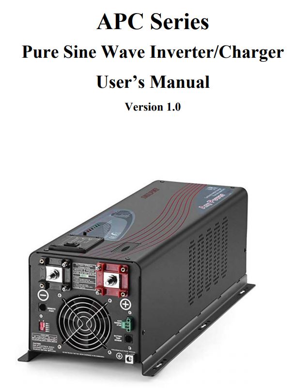
sungoldpower APC Series Pure Sine Wave Inverter/Charger
1. Important Safety Information
 WARNING!This manual contains important instructions for all APC Inverter/Charger models that shall be followed during the installation and maintenance of the inverter.
1-1. General Safety Precautions1-1-1.Do not expose the Inverter to rain, snow, spray, bilge, or dust. To reduce the risk of hazard, do not cover or obstruct the ventilation openings. Do not install the Inverter in a zero-clearance compartment. Overheating may result. Allow at least 30CM(11.81 inches) of clearance around the inverter for airflow. Make sure that the air can circulate freely around the unit. A minimum airflow of 145CFM is required. 1-1-2. To avoid a risk of fire and electronic shock. Make sure that existing wiring is in good electrical condition, and that wire size is not undersized. Do not operate the Inverter with damaged or substandard wiring. 1-1-3. This equipment contains components that can produce arcs or sparks. To prevent fire or explosion do not install in compartments containing batteries or flammable materials or in locations that require ignition protected equipment. This includes any space containing gasoline-powered machinery, fuel tanks, or joints, fittings, or other connections between components of the fuel system. See Warranty for instructions on obtaining service. 1-1-4. Do not disassemble the Inverter/Charger. It contains no user-serviceable parts. Attempting to service the Inverter/Charger yourself may result in a risk of electrical shock or fire. Internal capacitors remain charged after all power is disconnected. 1-1-5. To reduce the risk of electrical shock, disconnect both AC and DC power from the Inverter/Charger before attempting any maintenance or cleaning. Turning off controls will not reduce this riskCAUTION: Equipment damageThe output side of the inverter’s AC wiring should at no time be connected to public power or a generator. This condition is far worse than a short circuit. If the unit survives this condition, it will shut down until corrections are made. Installation should ensure that the inverter’s AC output is, at no time, connected to its AC input.Warning: Limitations On UseSPECIFICALLY, PLEASE NOTE THAT THE APC SERIES INVERTER/CHARGER SHOULD NOT BE USED IN CONNECTION WITH LIFE SUPPORT SYSTEMS OR OTHER MEDICAL EQUIPMENT OR DEVICES.
1-2. Precautions When Working with Batteries1-2-1. If battery acid contacts skin or clothing, wash immediately with soap and water. If acid enters the eye, immediately flood the eye with running cold water for at least 20 minutes and get medical attention immediately. 1-2-2. Never smoke or allow a spark or flame in the vicinity of the battery or engine. 1-2-3. Do not drop a metal tool on the battery. The resulting spark or short-circuit on the battery of another electrical part may cause an explosion. 1-2-4. Remove personal metal items such as rings, bracelets, necklaces, and watches when working with a lead-acid battery. A lead-acid battery produces a short-circuit current high enough to weld a ring or the like to metal, causing a severe burn. 1-2-5. To reduce the risk of injury, charge only rechargeable batteries such as deep-cycle lead-acid, lead-antimony, lead-calcium gel cell, absorbed mat, NiCad/NiFe, or Lithium battery. Other types of batteries may burst, causing personal injury and damage.
2. Introduction
2-1. General Information
This Series Pure Sine Wave Inverter is a combination of an inverter, battery charger, and AC auto-transfer switch into one complete system with a peak conversion efficiency of 88%. It is packed with unique features and it is one of the most advanced inverter/chargers in the market today. It features power factor corrected, sophisticated multi-stage charging, and pure sine wave output with unprecedentedly high surge capability to meet demanding power needs of inductive loads without endangering the equipment.
For the regular model, when utility AC power cuts off(or falls out of acceptable range), the transfer relay is de-energized and the load is automatically transferred to the Inverter output. Once the qualified AC utility is restored, the relay is energized and the load is automatically reconnected to the AC utility. The APC Series Inverter is equipped with a powerful charger of up to110Amps (depending on the model). The overload capacity is 300% of continuous output for up to 20 seconds to reliably support tools and equipment longer
Another important feature is that the inverter can be easily customized to Battery priority via a DIP switch, this helps to extract maximum power from the battery in renewable energy systems. Thus, the APC Series Pure Sine Wave Inverter is suitable for Renewable energy systems, Utility, RV, Marin, and Emergency appliances.
To get the most out of the power inverter, it must be installed, used, and maintained properly. Please read the instructions in this manual before installing and operating.
2-2. Application
Power tools — circular saws, drills, grinders, sanders, buffers, weed and hedge trimmers, air compressors.Office equipment — computers, printers, monitors, facsimile machines, scanners. Household items — vacuum cleaners, fans, fluorescent and incandescent lights, shavers, sewing machines.Kitchen appliances — coffee makers, blenders, ice markers, toasters.Industrial equipment — metal halide lamp, high pressure sodium lamp.Home entertainment electronics — television, VCRs, video games, stereos, musical instruments, satellite equipment.
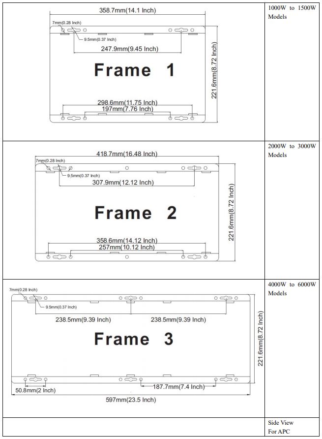
2.3 Mechanical Drawing
APC 1KW to 3KW Models
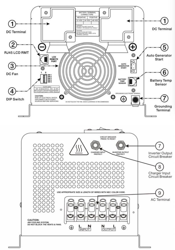
APC 4KW to 6KW Models
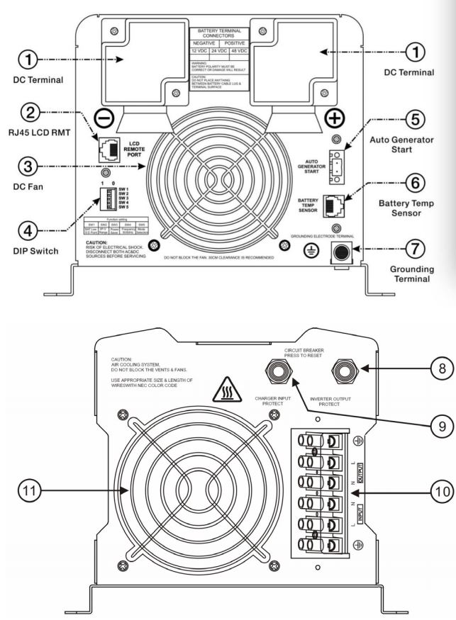
8 Inverter Output Protection Circuit Breaker9 Charger Input Protection Circuit Breaker10 AC Terminal Block11 AC Fan
2.4 Features
- Smart Remote Control (RMT)
- Designed to Operate under Harsh Environment
- DC Start & Automatic Self-Diagnostic Function
- Compatible with Both Linear & Non-Linear Load
- Easy to Install & Easy to Operate & Easy to Solve
- Low DC Voltage Supports Home & Office Appliances
- Powerful Charge Rate Up to 120Amp, Selectable From 0%-100%
- High-Efficiency Design & “Power Saving Mode” to Conserve Energy
- Battery Priority Mode, Designates the Inverter-Preferred UPS Configuration
- 13 Vdc Battery Recover Point, Dedicated for Renewable Energy Systems
- 8 pre Set Battery Type Selector plus De-sulphation for Totally Flat Batteries
- 4-step Intelligent Battery Charging, PFC (Power Factor Correction) for Charger
- 8 ms Typical Transfer Time Between Utility & Battery, Guarantees Power Continuity
- 15s Delay Before Transfer when AC Resumes, Protection for Load when Used with Generator
2.5 Electrical Performance
2.5.1 Inverter
TopologyThe APC inverter/charger is built according to the following topology. Inverter: Full Bridge Topology. AC Charger: Isolate Boost Topology Because of high-efficiency Mosfets and 16bit, 4.9MHz microprocessor and heavy transformers, it outputs PURE SINE WAVE AC with an average THD of 10% (Min5%, Max 15%) depending on the load connected and battery voltage. The peak efficiency of the APC series is 88%.
Overload CapacityThe APC series inverters have different overload capacities, making them ideal to handle demanding loads. 1 For 110%<Load<125%(±10%), no audible alarm in 14 minutes, beeps 0.5s every 1s in the 15th minute, and Fault(Turn off) after the 15th minute. 2 For 125%<Load<150%(±10%), beeps 0.5s every 1s and Fault(Turn off) after the 1 minute. 3 For 300%Load>150%(±10%), beeps 0.5s every 1s and Fault(Turn off) after the 20s.
2.5.2 AC Charger
APC Series is equipped with an active PFC (Power Factor Corrected) multistage battery charger. The PFC feature is used to control the amount of power used to charge the batteries in order to obtain a power factor as close as possible to 1. Unlike other inverters whose max charging current decreases according to the input AC voltage, the APC series charger is able to output max current as long as input AC voltage is in the range of 164-243VAC (95-127VAC for 120V model), and AC freq is in the range of 48-54Hz(58-64Hz for 60Hz model). The APC series inverter is with a strong charging current of 120Amp (for 4KW,12V), and the max charge current can be adjusted from 0%-100% via a liner switch at the right of the battery type selector. This will be helpful if you are using our powerful charger on a small capacity battery bank. Fortunately, the liner switch can effectively reduce the max charging current to 20% of its peak. Choosing “0” in the battery type selector will disable the charging function.
There are mainly 3 stages:Bulk Charging: This is the initial stage of charging. While Bulk Charging, the charger supplies the battery with a controlled constant current. The charger will remain in Bulk charge until the Absorption charge voltage (determined by the Battery Type selection) is achieved. The software timer will measure the time from A/C start until the battery charger reaches 0.3V below the boost voltage, then take this time asT0 and T0×2 = T1.Absorb Charging: This is the second charging stage and begins after the absorb voltage has been reached. Absorb Charging provides the batteries with a constant voltage and reduces the DC charging current in order to maintain the absorb voltage setting. In this period, the inverter will start a T1 timer; the charger will keep the boost voltage in Boost CV mode until the T1 timer has run out. Then drop the voltage down to the float voltage. The timer has a minimum time of 1 hour and a maximum time of 12 hours.Float Charging: The third charging stage occurs at the end of the Absorb Charging time. While Float charging, the charge voltage is reduced to the float charge voltage (determined by the Battery Type selection*). In this stage, the batteries are kept fully charged and ready if needed by the inverter. If the A/C is reconnected or the battery voltage drops below 12Vdc/24Vdc/48Vdc, the charger will reset the cycle above. If the charge maintains the floating state for 10 days, the charger will deliberately reset the cycle to protect the battery.
Table 2.5.1 Battery Charging Processes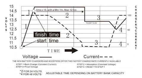
Table 2.5.2 Battery Type Selector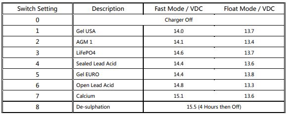
For 12Vdc Mode Series (*2 for 24Vdc Mode ; *4 for 48Vdc Mode)
De-sulphationThe de-sulphation cycle on switch position 8 is marked in red because this is a very dangerous setting if you do not know what you are doing. Before ever attempting to use this cycle you must clearly understand what it does and when and how you would use it. What causes sulphation? This can occur with infrequent use of the batteries(nor), or if the batteries have been left discharged so low that they will not accept a charge. This cycle is a very high voltage charge cycle designed to try to break down the sulfated crust that is preventing the plates from taking a charge and thus allow the plates to clean up and so accept charge once again.
Charging depleted batteriesThe APC series inverter allows start-up and through power with depleted batteries. For the 12VDC model, after the battery voltage goes below 10V, if the switch is still (and always) kept in “ON” position, the inverter is always connected with the battery, and the battery voltage does not drop below 2V, the inverter will be able to charge the battery once qualified AC inputs are present. Before the battery voltage goes below 9VDC, the charging can be activated when the switch is turned to “Off”, then to “ON”.
When the voltage goes below 9VDC, and you accidentally turn the switch to OFF or disconnect the inverter from a battery, the inverter will not be able to charge the battery once again, because the CPU loses memory during this process.
Tabel 2.5.3 AC Charging Current for APC model
The charging capacity will go to peak in around 3 seconds. This may cause a generator to drop frequency, making inverter transfer to battery mode. It is suggested to gradually put charging load on the generator by switching the charging switch from min to max, together with the 15s switch delay, our inverter gives the generator enough time to spin up. This will depend on the size of the generator and the rate of charge.
2.5.3 Transfer
While in the Standby Mode, the AC input is continually monitored. Whenever AC power falls below the VAC Trip voltage (154 VAC, default setting for 230VAC,90VAC for 120VAC), the inverter automatically transfers back to the Invert Mode with minimum interruption to your appliances – as long as the inverter is turned on. The transfer from Standby mode to Inverter mode occurs in approximately 8 milliseconds. And it is the same time from Inverter mode to Standby mode. Though it is not designed as a computer UPS system, this transfer time is usually fast enough to keep your equipment powered up. There is a 15-second delay from the time the inverter senses that continuously qualified AC is present at the input terminals to when the transfer is made. This delay is built in to provide time for a generator to spin up to a stable voltage and avoid relay chattering. The inverter will not transfer to the generator until it has locked onto the generator’s output. This delay is also designed to avoid frequent switching when the input utility is unstable.
2.5.4 Auto frequency adjust
The inverter is with Auto Frequency adjust function. The factory default configuration for 220/230/240VAC inverter is 50Hz, and 60Hz for 100/110/120VAC inverter. While the output freq can be easily changed once a qualified freq is applied to the inverter. If you want to get 60Hz from a 50Hz inverter, just input 60Hz power, and the inverter will automatically adjust the output freq to 60Hz and vice versa.
2.5.5 Automatic Voltage Regulation(Optional)
The automatic voltage regulation function is for full series of APC Pure Sine Wave Inverter/ Charger except for split phase models including APC 1000W~6000W. Instead of simply bypassing the input AC to power the loads, the APC series inverter stabilizes the input AC voltage to a range of 230V/120V±10%. Connected with batteries, the APC/APPS Series inverter will function as a UPS with a max transfer time of 10 ms. With all the unique features our inverter provides, it will bring you long-term trouble-free operation beyond your expectation.
Function Introduction
Table 2.5.5 Input Voltage Transfer Points![]()
2.5.6 Power Saver Mode
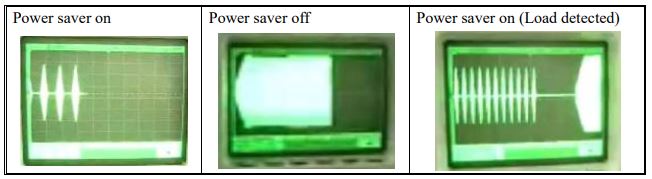
There are 3 different working statuses for the APC inverter: “Power Saver Auto” “Power Saver Off” and “Power Off”. When the power switch is in the “Unit Off” position, the inverter is powered off. When the power switch is turned to either “Power Saver Auto” or “Power Saver Off”, the inverter is powered on. The power saver function is designed to conserve battery power when AC power is not or rarely required by the loads. In this mode, the inverter pulses the AC output looking for an AC load (i.e., electrical appliance). Whenever an AC load (greater than 25 watts) is turned on, the inverter recognizes the need for power and automatically starts inverting and output goes to full voltage. When there is no load (or less than 25 watts) detected, the inverter automatically goes back into search mode to minimize energy consumption from the battery bank. In “Power saver on” mode, the inverter will draw power mainly in sensing moments, thus the idle consumption is significantly reduced. The inverter is factory defaulted to detect load for 250ms every 30 seconds. This cycle can be customized to 3 seconds turn SW3 on the DIP switch.
Note: The minimum power of load to take inverter out of sleep mode (Power Saver On) is 25 Watts.
When in the search sense mode, the green power LED will blink and the inverter will make a ticking sound. At full output voltage, the green power LED will light steadily and the inverter will make a steady humming sound. When the inverter is used as an “uninterruptible” power supply the search sense mode or “Power Saver On” function should be defeated.
ExceptionsSome devices when scanned by the load sensor cannot be detected. Small fluorescent lights are the most common example. (Try altering the plug polarity by turning the plug over.) Some computers and sophisticated electronics have power supplies that do not present a load until line voltage is available. When this occurs, each unit waits for the other to begin. To drive these loads either a small companion load must be used to bring the inverter out of its search mode, or the inverter may be programmed to remain at the full output voltage.
2.5.7 Protections
The APC series inverter is equipped with extensive protections against various harsh situations/faults. These protections include: AC Input over-voltage protection/AC Input low voltage protection Low battery alarm/High battery alarm Over temperature protection/Overload protection Short Circuit protection (1s after fault) Back feeding protection
When Over temperature /Overload occur, after the fault is cleared, the master switch has to be reset to restart the inverter. The Low battery voltage trip point can be customized from defaulted value 10VDC to 10.5VDC thru the SW1 on the DIP switch. The inverter will go to Over temp protection when the heat sinks temp. 105ºC, and go to Fault (shutdown Output) after 30 seconds. The switch has to be reset to activate the inverter. The APC series Inverter has back-feeding protection which avoids presenting an AC voltage on the AC input terminal in Invert mode. After the reason for the fault is cleared, the inverter has to be reset to start working.
2.5.8 Remote control (Optional)

Apart from the switch panel on the front of the inverter, an extra switch panel connected to the RJ11 port at the DC side of the inverter thru a standard telephone cable can also control the operation of the inverter. If an extra switch panel is connected to the inverter via “remote control port”, together with the panel on the inverter case, the two panels will be connected and operated in parallel. Whichever first switches from “Off” to “Power saver off” or “Power saver on”, it will power the inverter on. If the commands from the two panels conflict, the inverter will accept the command according to the following priority: Power saver on> Power saver off> Power off Only when both panels are turned to “Unit Off” position will the inverter be powered off. The Max length of the cable is 10 meters.
WARNINGNever cut the telephone cable when the cable is attached to the inverter and the battery is connected to the inverter. Even if the inverter is turned off. It will damage the remote PCB inside if the cable is short-circuited during cutting.
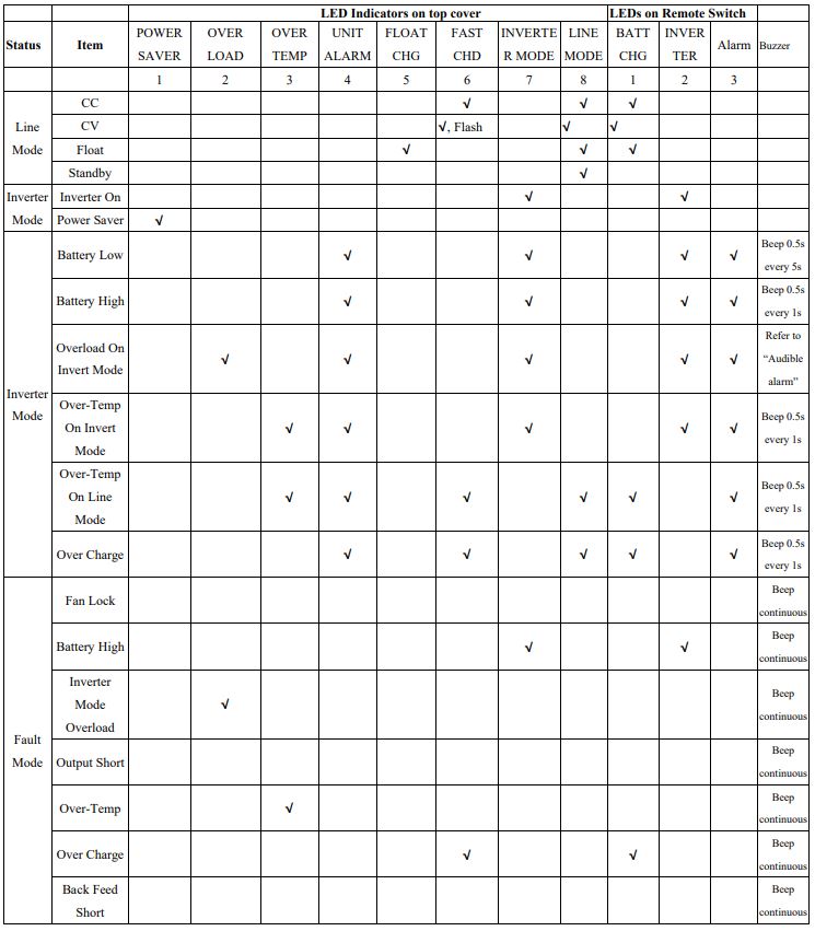
2.5.9 LED Indicator & LCD
Table 2.5.7 APC Series LED Indicators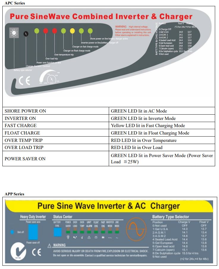

Table 2.5.8 APC/APP Series LCD Indicator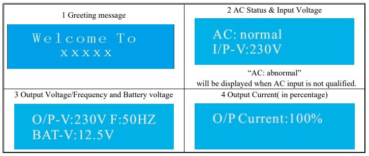
2.5.10 Audible Alarm
Table 2.5.9 APC Series Audible Alarm Spec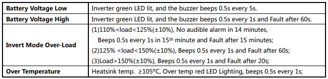
2.5.11 FAN Operation
For 1-3KW, there is one multiple controlled DC fan that starts to work according to the following logic. For 4-6KW, there is two multiple controlled DC fan and one AC fan. The DC fan will work in the same way as the one on 1-3KW, while the AC fan will work once there is AC output from the inverter. So when the inverter is in power saver mode, the AC fan will work from time to time in response to the pulse sent by the inverter in power saver mode. The Operation of the DC fan at the DC terminal side is controlled by the following logic (Refer to Table 2.5.10):
Table 2.5.10 APC Series Fan Operation Logic
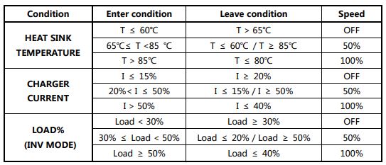
Allow at least 30CM of clearance around the inverter for airflow. Make sure that the air can circulate freely around the unit. Variable-speed fan operation is required in invert and charge mode. This is to be implemented in such a way as to ensure high reliability and safe unit and component operating temperatures in an operating ambient temperature up to 50°C.
- Speed to be controlled in a smooth manner as a function of internal temperature and/or current.
- The fan should not start/stop suddenly.
- The fan should run at the minimum speed needed to cool the unit.
- Fan noise level target <60db at a distance of 1m.
2.5.12 DIP Switches
On the rear panel of the inverter, there are 4 DIP switches that enable users to customize the performance of the device.
Table 2.5.11 APC Series Dip Switch Function Setting
SW1: Low Battery Trip Volt:For the 12VDC model, the Low Battery Trip Volt is set at 10.0Vdc by a typical deep cycle lead-acid battery. It can be customized to 10.5Vdc using SW1 for sealed car battery, this is to prevent batteries from over-discharging while there is only a small load applied on the inverter. (*2 for 24VDC, *4 for 48VDC)
SW2:AC Input Range:There are different acceptable AC input ranges for different kinds of loads. For some relatively sensitive electronic devices, a narrow input range of 184-253VAC (100-135V for 120VAC model) is required to protect them. While for some resistive loads which work in a wide voltage range, the input AC range can be customized to 154-253VAC (90-135V for 120VAC model), this helps to power loads with the most AC input power without frequent switches to the battery bank.
SW3:Power Saver Auto Setting:The inverter is factory defaulted to detect load for 250ms every 5 seconds. This cycle can be customized to 3 seconds through the SW3 on the DIP switch.
SW4: Adjust 50hz/60hzThe output frequency of the inverter can be set at either 50Hz or 60Hz by SW4.
SW5:Solar/AC Priority:Our inverter is designed with AC priority by default. This means, when AC input is present, the battery will be charged first, and the inverter will transfer the input AC to power the load. Only when the AC input is stable for a continuous period of 15 days, the inverter will start a battery inverting cycle to protect the battery. After 1 cycle normal charging and ac throughput will be restored. The AC Priority and Battery Priority switch are SW4. When you choose battery priority, the inverter will invert from the battery despite the AC input. Only when the battery voltage is reached a low voltage alarm point(10.5V for 12V), the inverter transfer to AC Input charges the battery, and switch back to the battery when the battery is charged fully. This function is mainly for wind/solar systems taking utility power as backup.
2.5.13 Other features
Battery voltage recovery startAfter low battery voltage shut off (10V for 12V model/20V for 24V model/40V for 48V model), the inverter is able to restore operation after the battery voltage recovers to 13Vdc/26Vdc/52Vdc (with power switch still in the “On” position). This function helps to save the users extra labor to reactivate the inverter when the low battery voltage returns to an acceptable range in renewable energy systems. The built-in battery charger will automatically reactivate as soon as the city/generator ac has been stable for 15 seconds.
WARNING Never leave the loads unattended, some loads (like a Heater) may cause accidents in such cases. It is better to shut everything down after a low voltage trip than to leave your load on, due to the risk of fire.
Auto Gen Start(optional)The inverter can be customized to start up a generator when the battery voltage goes low. When the inverter goes to a low battery alarm, it can send a signal to start a generator and turn the generator off after battery charging is finished. The auto-gen start feature will only work with generators designed to work with this feature. There is an open/close relay that will short circuit the positive and negative cable from a generator. The input DC voltage can vary, but the Max current the relay can carry is 16Amp.Conformal CoatingThe entire line of inverters has been processed with a conformal coating on the PCB, making it water, rust, and dust resistant. While these units are designed to withstand corrosion from the salty air, they are not splash-proof.
3 Installation
3.1 Location
Follow all the local regulations to install the inverter.Please install the equipment in a location that is Dry, Clean, Cool and that has good ventilation.Working temperature: -10°C-40°CStorage temperature: -40-70°CRelative Humidity: 0%-95%non-condensingCooling: Forced air
3.2 DC Wiring recommendation
It is suggested the battery bank be kept as close as possible to the inverter. The following table is a suggested wiring option for 1 meter DC cable.Please find the following minimum wire size. In case of DC cable longer than 1m, please increase the cross-section of cable to reduce the loss.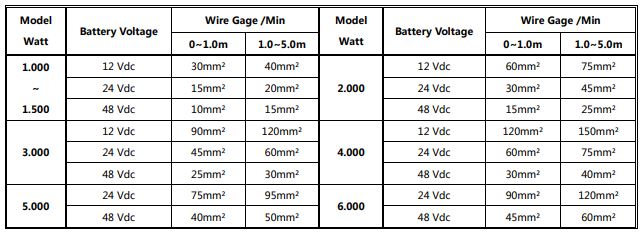
Please note that if there is a problem obtaining for example 90mm²cable, use 2*50mm²or 3*35mm². One cable is always best, but the cable is simply copper and all you require is the copper, so it does not matter if it is one cable or 10 cables as long as the square area adds up. Performance of any product can be improved by thicker cable and shorter runs, so if in doubt round up and keep the length as short as possible.
3.3 AC Wiring
We recommend using a 10-5Awg wire to connect to the ac terminal block.
There are 3 different ways of connecting to the terminal block depending on the model. All the wirings are CE compliant, Call our tech support if you are not sure about how to wire any part of your inverter. WARNING The output voltage of this unit must never be connected to its input AC terminal, overload or damage may result. Always switch on the inverter before plugging in any appliance.
3.4 Install Flange
4 Troubleshooting Guide
Troubleshooting contains information about how to troubleshoot possible error conditions while using the APC Series Inverter & Charger. The following chart is designed to help you quickly pinpoint the most common inverter failures.
Indicator and Buzzer For APC


*The reason for the noise from the transformer and/or caseWhen in inverter mode and the transformer and/or case of the inverter sometimes may vibrate and make noise.
The noise may come from the transformer. According to the characteristics of our inverter, there is one type of load that will most likely cause rattles of the transformer, that is a half-wave load, load that uses only a half cycle of the power(see figure 1). This trend causes an imbalance of the magnetic field of the transformer, reducing it’s rated working freq from 20KHz too, say, maybe 15KHz (it varies according to different loads). This way, the freq of noise falls exactly into the range (200Hz-20KHz) that the human ear can sense. The most common load of such kind is a hair drier.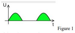 If the noise comes from the case. Normally when loaded with inductive loads, the magnetic field generated by the transformer keeps attracting or releasing the steel case at a specific freq, this may also cause noise. Reducing the load power or using an inverter with a bigger capacity will normally solve this problem. The noise will not do any harm to the inverter or the loads.
5 Warranty
We offer a 1-year limited warranty. The following cases are not covered under warranty. 1DC polarity reverse. The inverter is designed without DC polarity reverse protection. A polarity reverse may severely damage the inverter.2 Wrong AC wiring3 Operating in a wet environment.4 Operating with an undersized generator or generator with an unqualified waveform.
Appendix 1
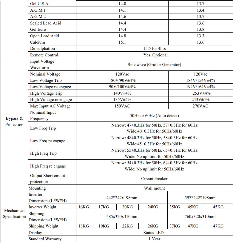
Inverter & AC Charger
Electrical Specifications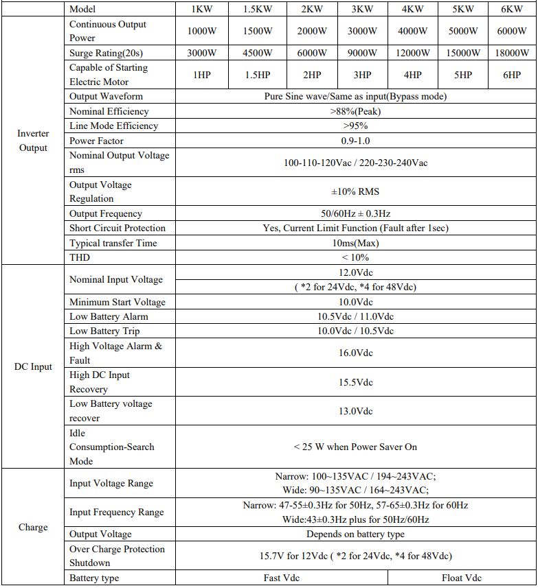
References
[xyz-ips snippet=”download-snippet”]