SBR096 High Voltage LFP Battery
SBR096/128/160/192/224/ 256High Voltage LFP BatteryUser ManualSBR096-256-UEN-Ver12-202103 Version: 1.2SBR096-256-UEN-Ver12-202103 Version: 1.2SBR096/128/160/192/224/256 High Voltage LFP Battery User Manual
All Rights ReservedAll Rights Reserved No part of this document can be reproduced in any form or by any means without the prior written permission of Sungrow Power Supply Co., Ltd (hereinafter “SUNGROW”). Trademarksand other Sungrow trademarks used in this manual are owned by Sungrow Power Supply Co., Ltd. All other trademarks or registered trademarks mentioned in this document are owned by their respective owners. Software Licenses · It is prohibited to use data contained in firmware or software developed bySUNGROW, in part or in full, for commercial purposes by any means. · It is prohibited to perform reverse engineering, cracking, or any other operations thatcompromise the original program design of the software developed by SUNGROW.Sungrow Power Supply Co., Ltd. Address: No.1699 Xiyou Rd., New & High Tech Zone, Hefei, 230088, China. Tel: +86 551 6532 7834 Website: www.sungrowpower.comI
About This ManualThe manual mainly describes the product information, guidelines for installation, operation and maintenance. The manual cannot include complete information the system (i. e. the inverter), just the battery. The reader can get additional information about other devices at www.sungrowpower.com or on the webpage of the respective component manufacturer. Validity This manual is valid for the following battery models: · SBR096 · SBR128 · SBR160 · SBR192 · SBR224 · SBR256 They will be referred to as “battery” hereinafter unless otherwise specified. Target Group This manual is intended for battery owners who will have the ability to interact with the battery and qualified personnel who are responsible for the installation and commissioning of the battery. Qualified personnel should have the following skills: · Training for installation and commissioning of electrical system, as well as dealingwith hazards · Knowledge of the manual and other related documents · Knowledge of the local regulations and directives How to Use This Manual Read the manual and other related documents before performing any work on the battery. Documents must be stored carefully and be available at all times. Contents may be periodically updated or revised due to the product development. It is probably that there are changes of manual in the subsequent battery edition. The latest manual can be acquired via visiting the website at support.sungrowpower.com. Symbols Important instructions contained in this manual should be followed during installation, operation and maintenance of the inverter. They will be highlighted by the following symbols.II
Indicates a hazard with a high level of risk that, if not avoided, will result in death or serious injury.Indicates a hazard with a medium level of risk that, if not avoided, could result in death or serious injury.Indicates a hazard with a low level of risk that, if not avoided, could result in minor or moderate injury.Indicates a situation that, if not avoided, could result in equipment or property damage.Indicates additional information, emphasized contents or tips that may be helpful, e.g. to help you solve problems or save time. Abbreviation BMS: Battery Management System BMU: Battery Management Unit CAN: Controller Area Network CMU: Battery Cluster Management Unit LFP: Lithium iron phosphate PCS: Power Conversion System SOC: State of ChargeIII
ContentsAll Rights Reserved ………………………………………………………………………………………..I About This Manual ………………………………………………………………………………………..II1 Safety ……………………………………………………………………………………………….. 11.1 Notices for Safe Use ………………………………………………………………………… 1 1.2 Battery Handling Information ……………………………………………………………… 2 1.3 Emergency Situations ………………………………………………………………………. 31.3.1 Leaking Batteries …………………………………………………………………….. 3 1.3.2 Fire……………………………………………………………………………………….. 3 1.3.3 Wet Batteries………………………………………………………………………….. 4 1.3.4 Damaged Batteries………………………………………………………………….. 42 Product Description ………………………………………………………………………… 62.1 Product Introduction…………………………………………………………………………. 6 2.2 Terminal Description…………………………………………………………………………. 8 2.3 Symbols on the Product ……………………………………………………………………. 9 2.4 LED Indicator ………………………………………………………………………………… 103 Unpacking and Storage ………………………………………………………………… 113.1 Unpacking and Inspection ……………………………………………………………….. 11 3.2 Scope of Delivery …………………………………………………………………………… 11 3.3 Storage ………………………………………………………………………………………… 124 Mounting ………………………………………………………………………………………… 134.1 Safety during Mounting …………………………………………………………………… 13 4.2 Location Requirements …………………………………………………………………… 13 4.3 Installation Environment Requirements ………………………………………………. 13 4.4 Installation Clearance Requirements………………………………………………….. 13 4.5 Installation Tools…………………………………………………………………………….. 14 4.6 Installing the Battery ……………………………………………………………………….. 155 Parallel SystemOptional ………………………………………………………… 215.1 Scope of Delivery …………………………………………………………………………… 21 5.2 Mounting the Junction Box ………………………………………………………………. 21 5.3 Terminal Description (Junction Box)…………………………………………………… 22 5.4 Connection Diagram in Parallel System ……………………………………………… 23V
5.5 Installing the SUNCLIX Connector……………………………………………………… 25 5.6 Installing the COMM IN Connector…………………………………………………….. 276 Commissioning ………………………………………………………………………………. 306.1 Inspection before Commissioning……………………………………………………… 30 6.2 Commissioning Procedure ………………………………………………………………. 307 Decommissioning the Battery ……………………………………………………… 31 8 Troubleshooting and Maintenance ……………………………………………… 328.1 Troubleshooting …………………………………………………………………………….. 32 8.2 Maintenance …………………………………………………………………………………. 369 Appendix ………………………………………………………………………………………… 389.1 Technical Data ………………………………………………………………………………. 38 9.2 Quality Assurance ………………………………………………………………………….. 41 9.3 Contact Information ……………………………………………………………………….. 42VI
1 SafetyThe device has been designed and tested strictly according to international safety regulations. Read all safety instructions carefully prior to any work and observe them at all times when working on or with the device. Incorrect operation or work may cause: · Injury or death to the operator or a third party; · Damage to the device and other properties. All detailed work-related safety warnings and notes will be specified at critical points in this manual.The safety instructions in this manual cannot cover all the precautions that should be followed. Perform operations considering actual onsite conditions. SUNGROW shall not be held liable for any damage caused by violation of the safety instructions in this manual.1.1 Notices for Safe UseRead all safety instructions carefully prior to any work and observe them at all times when working on or with the battery. Failure to observe the precautions described in this section can cause serious injury to persons or damage to property.Risk of explosion · Do not subject the battery to any strong force. · Do not mechanically damage the battery (pierce, deform, strip down, etc.) · Do not heat the battery or dispose of the battery in a fire. · Do not install the battery in potentially explosive environments.1
1 Safety
User Manual
Risk of fire· Do not expose the battery to temperatures in excess of 60°C.· Do not place the battery near a heat source, such as direct sunlight, a fireplace, a thermally uninsulated wall exposed to sunlight, hot water, or a heater.· Keep sources of ignition such as sparks, flames, and smoking materials away from the battery.
Risk of electric shock · Do not disassemble the battery. · Do not handle a wet battery or use wet tools. · Do not soak the battery in water or expose it to moisture or liquids. · Keep the battery away from children and animals. · Wear suitable clothing, guards and gloves to prevent you from direct contactwith the DC voltage. · Use insulated tools during working with battery. · Set aside metal jewelry before working on the DC circuit.1.2 Battery Handling Information
Comply with local standards for use with the battery.Any man-made damage will void the limited warranty for the battery. Handle the battery with care to protect it from damage. · Use the battery only as intended and designed. · The battery must only be installed at a suitable location. · Make sure the battery is well connected to ground before use. · Do not use the battery if it is defective, appears cracked, broken or damaged, or failsto operate. · Do not use the battery together with other types of batteries. · Do not pull, drag or step on the battery. · Do not leave any foreign objects inside the battery.2
User Manual
1 Safety
· Do not repair or modify the battery. It is not user serviceable. · Do not pull out any cables when the battery is powered on. · Do not damage the sheath of cables, wire harness and connectors. · While the battery is charged, used and stored, keep it away from materials that areprone to electric discharge, including static discharge. · Keep the battery away from babies and children to avoid any accidents. · Cover terminals with insulating tape before proper disposal.
1.3 Emergency Situations1.3.1 Leaking BatteriesAbuse/misuse/damage of the battery may cause increasing of internal pressure in the battery cells. It may result in the electrolyte venting. In the event that battery electrolyte is released:· Do not enter the room under any circumstance. · Avoid contact with the leaking liquid or gas. · Call the Local Emergency number or Fire Brigade if necessary.If one is exposed to the leaking substance, follow the suggestions below to minimize the chance of injury:· Inhalation: Evacuate the contaminated area, and seek medical aid. · Eye contact: Rinse eyes with copious amounts of water using for at least 15 minutes,and seek medical aid immediately. · Skin contact: Wash the affected area thoroughly with plenty of water for at least 15minutes. If possible, remove or saturate contaminated clothing with water. Seek medical aid if the patient is distressed. · Ingestion: Induce vomiting, and seek medical aid immediately.Wipe out the contacted area with a sponge or cloth that is soaked in water until you obtain medical aid. These materials can damage skin and eyes, causing blindness.1.3.2 FireFire may occur with the battery despite its careful design. Likewise, a fire near the battery can cause it to catch fire. Protective equipment A respirator is not required during normal operations. In the event of a fire, hazardous fumes including carbon monoxide, carbon dioxide, and/ or various hydrocarbons may be emitted. To comply with the Personal Protective Equipment Directive (89/686/EEC), use a full-face self-contained breathing apparatus (SCBA) with full protective gear during fire fighting.
3
1 SafetyFire fighting
User Manual
In the event of a fire, only qualified firefighters with appropriate protective equipment are permitted to enter the room where the battery is located. Battery fires can take up to 24 hours to fully extinguish. Consider allowing the system to burn. Smoke indicates that the battery is still burning. Always note that there is a risk of the battery re-igniting.Proceed as follows for firefighting.1 Shut off any connected power system or electronics such as the battery, battery isolator, PV DC isolator(s), AC isolator, solar supply main switch and normal supply main switch.2 Perform an adequate knock down on the fire before entering the incident’s hot zone.3 If the battery catches on fire, use an firefighting sandor CO2 extinguisher to extinguish fire.4 If the battery becomes involved in fire or is bent, damaged or breached in any way, or if suspect that the battery is heating, use large amounts of water to cool the battery. Do not try to extinguish the fire with a small amount of water. Always obtain an additional water supply.5 If the fire is not from the battery and has not spread to it yet, use an ABC fire extinguisher to extinguish the fire. Remove batteries and other ignition sources from the scene of a fire.1.3.3 Wet BatteriesIf the battery is submerged in water, do not let people access it, and then contact Sungrow or an authorized service partner for technical support. If a battery is submerged in water or flooded, first, switch off all circuit breakers in the system to cut off the power supply to the battery. Wait until floodwaters subside and do not approach near battery. If someone needs to go into the flooded water, wear insulated full length rubber boots and gloves. Do not use a flooded battery again.1.3.4 Damaged BatteriesThe battery consists of lithium ion cells. These are considered dry cell batteries. If damaged, only a small amount of battery fluid can leak. A damaged battery can cause rapid heating of the battery cells. If you notice smoke coming from the battery area, assume that the battery is burning and take appropriate action as described in “1.3.2 Fire”.4
User Manual
1 Safety
Damaged batteries are dangerous and must be handled with extreme caution. They are not fit for use and may pose a danger to people or property. If a battery seems to be damaged:1 Pack it in its original container. 2 Store it in a separated room like the installation place. 3 Contact SUNGROW.
A damaged battery may release dangerous material and a flammable gas mixture. Never try to repair the battery even if you are qualified electrician.
5
2 Product Description2.1 Product IntroductionBrief Introduction The battery is designed for residential energy storage systems. The inbuilt battery management system monitors its operation and prevents the battery from operating beyond the specified limitations. This product is a high-voltage battery system with an operating voltage range between 168 V ~ 584 V. A battery system consist of 3 to 8 individual battery modules connected in series. The battery can be expanded to 4 units in parallel at most. Available in Q3, 2021.6
User Manual
2 Product Description
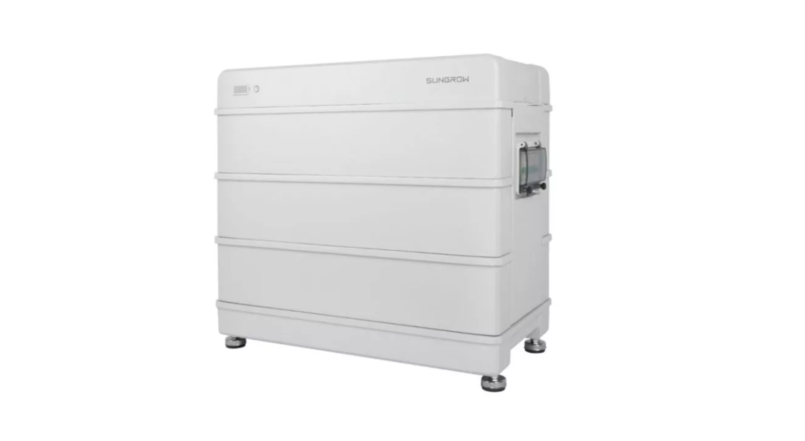
figure 2-1 Product overview
table 2-1 Design of the product
Position
Designation LED Indicator
LED indicator include the SOC indicator and the status indicator. The
A
status indicator is also used as the power button.
LED indicator indicates the SOC value and status of the battery. Nameplate
The nameplate clearly indentifies the product. The nameplate must
remain permanently attached to the product. You will find the following
B
information on the nameplate:
· SUNGROW logo and product model
· Technical data
· Product symbol
C
DC circuit breaker
7
2 Product DescriptionMajor Components
User Manual
Name A B C D EConfiguration Table
No. Model
1
SBR096
2
SBR128
3
SBR160
4
SBR192
5
SBR224
6
SBR256
Base1 1 1 1 1 1
Designation Base Battery module Top cover Switch gear Side cover
Batterymodule 3 4 5 6 7 8
Top cover1 1 1 1 1 1
Switchgear1 1 1 1 1 1
Side cover0 1 2 3 4 5
2.2 Terminal DescriptionAll electrical terminals are located at the switch gear.
8
User Manual
2 Product Description
No.
Label
Description
· To enable the communication between the inverter
1
COMM
and the battery
2
P-
3
P+
· For battery daisy chain The system negative terminal, connected to the inverter negative terminal The system positive terminal, connected to the inverter positive terminal
4
Grounding terminal, connected to the ground
DC circuit
To connect/disconnect the DC circuit, for power-on,
5
breaker
power-off, and short-circuit protection
2.3 Symbols on the Product
Symblo
Explanation Pay attention to the danger. Do not operate this product in the live status! No open flames Do not expose to flame, incinerate, puncture, or impact. Electric shock hazard Serviced by qualified personnel only. Out of reach from children.TÜV mark of conformity
TÜV mark of conformity CE mark of conformity
9
2 Product DescriptionSymblo
User ManualExplanation Do not dispose in trash. Compacting a lithium ion battery is dangerous as it can explode. Please recycle this lithium ion battery. Do not discard.Read the user manual before maintenance! This is a protective grounding terminal, which should be grounded securely to protect the safety of operators.
2.4 LED IndicatorLED indicators include the SOC indicator and the status indicator. The status indicator is also used as the power button. SOC Indicator The SOC indicator indicates the current SOC value of the battery. One bar indicates the SOC value of 10%.
Status Indicator The Status indicator indicates the current state of the battery.
LED LED colorindicator Blue Red
LED stateON Slow blink Period: 2 s Fast blink Period: 0.5 s ONBlink
Definition Normal operation (without fault) The battery is at power-on or standby state (without fault).The battery is at firmware update state.A system fault has occured. The battery is at power-on or standby state (with primary fault).
The status indicator can be used to power on or off the battery.
Operation Press and hold for less than 2 seconds Press and hold for more than 4 seconds
Definition To power on the battery To power off the battery
10
3 Unpacking and Storage3.1 Unpacking and InspectionThe device is thoroughly tested and strictly inspected before delivery. Nonetheless, damage may still occur during shipping. For this reason, please conduct a thorough inspection after receiving the device. · Check the packing case for any visible damage. · Check the scope of delivery for completeness according to the packing list. · Check the inner contents for damage after unpacking. Contact SUNGROW or the supplier in case of any damage or incompleteness. Do not dispose of the original packing case. It is recommended to store the device in it.3.2 Scope of Delivery
Item A B C D E F G H I
Name Base Battery module Top coverSwitch gearBracket Side cover Harness Stud Foot (optional)
Quantity 1 3~8 1 1 1 0~5 1 1 411
3 Unpacking and StorageItem J K L M N
Name M5 screw Expansion plug setM5 screw sets M6 fender washer Documents
Quantity8 ~ 18 2 3~4 2 1
User Manual
3.3 StorageProper storage is required if the battery is not installed immediately.· Store the battery in the original packing case with the desiccant inside.· Preferably, keep the temperature in the range of 15°C to 25°C. Store the battery within the temperature range of -10°C to 35°C for no more than 6 months.· The storage relative humidity must be always between 0 and 95 %, non-condensing.· Store the battery in a clean and dry place, without exposure to sunlight and rain. The storage location must be free of harmful gases, flammable/explosive products and corrosive chemicals. The battery should be prevented from mechanical impact, high pressure, high-intensity magnetic field and direct exposure to sunlight.· Pay attention to the harsh environment, such as sudden cooling/heating and collision, to avoid damage to the battery.· The number of stacking layers of battery modules with package must not exceed 6. It is strictly forbidden to directly stack batteries without package.· Regularly inspect the package for damage and insect bites. If any damage is found, the product should be replaced immediately.· The packing should be upright.· If stored for more than 6 months under the specified conditions, the battery needs to be charged once, until the system SOC is 50% to 80%. Preferably, use an inverter for forced charging.
12
4 Mounting4.1 Safety during MountingThis product or system must be operated by professionals! Failure to follow the safety instructions in this manual or operation of this product or system by non-professionals may cause severe personal injury or major property damage.Strictly follow local relevant standards and requirements in the whole process of installation.4.2 Location RequirementsSelect an optimal mounting location for safe operation, long service life and expected performance. The battery with IP55 can be installed both indoors and outdoors. Install the battery in a place convenient for electrical connection, operation, and maintenance.4.3 Installation Environment Requirements· The installation environment must be free of inflammable or explosive materials. · The location should be not accessible to children. · The ambient temperature must be always between 0 and 45 . · The relative humidity must be always between 0 and 95 %, non-condensing. · Avoid direct exposure to sun, rain and snow. · The battery should be well ventilated. Ensure air circulation.4.4 Installation Clearance Requirements· Reserve enough clearance around the battery to ensure sufficient space for heat dissipation.13
4 Mounting
User Manual
· In case of multiple batteries, reserve specific clearance between the batteries.
4.5 Installation ToolsInstallation tools include but are not limited to the following recommended ones. If necessary, use other auxiliary tools on site. table 4-1 Tool specification
Goggles
Dust mask
Protective gloves
Insulated shoes
14
User Manual
4 Mounting
Utility knife
Marker
Rubber mallet
Measuring tape
Level
Hammer drill (10)
Phillips screwdriver (M5)
Wrench (16 mm, 17mm)
4.6 Installing the BatteryThe SBR128 mounting will be used as an example. step 1 Align the base with the wall, and keep a distance of 13 mm to 28 mm between the baseand the wall. Mark the hole positions of the mounting bracket with a marker according to the required layout of holes.
A: Upper surface of the base
B: Base
figure 4-1 Layout of holes with the base as reference
You can choose not to mount SBR096/128 on the wall.
step 2 Drill the holes according to the marked positions, and install the expansion sleeves. 15
4 Mountingstep 3 (Optional) Install the feet of the battery.
User Manual
step 4 Position the base maintaining the required distance from the wall.
step 5 Place each battery module on top of the base.
16
User Manual
4 Mounting
When carrying the battery module, always be aware of its weight of 33 kg. step 6 Fix the battery modules with the included screws.step 7 Connect the switch gear to the base. 17
4 Mounting
User Manual
step 8 Fix the switch gear with the provided stud.When 4 or more than 4 battery modules are installed in one base, M5 screw set is required to secure the switch gear. The stud is mounted on the top of battery module. step 9 Fix the battery to the wall.18
User Manual
4 Mounting
The bracket is mounted on the top battery module. step 10Connect the harness.For communication between the battery and the inverter. Connect the communication cable from the “COMM” terminal of the battery to the inverter. Strip the insulation layer of the communication cable with a wire stripper, and lead the corresponding CAN1_H/CAN1_L signal cable out. Cut off the redundant signal cable and warp it with a heat-shrink tubing. Signal cable 1 white and orange cable is used as CAN1_H; and signal cable 2 orange cable is used as CAN1_L.19
4 Mountingstep 11Place the top cover and fix it with the screw provided.
User Manual
step 12(Optional) Install the side covers.
When 4 or more than 4 battery modules are installed in one base, side covers are required.– – End
20
5 Parallel SystemOptionalThe battery can be expanded to 4 units in parallel at most. Available in Q3, 2021.5.1 Scope of Delivery
Item A B C D E F G H I
Name Junction box Bracket Expansion plug setM4 screw set COMM IN connector SUNCLIX connector SUNCLIX power cablesCOMM OUT communication cable Grounding cable
Quantity1 1 3 2 1 4 1 1 1
5.2 Mounting the Junction Boxstep 1 Install the wall-mounting bracket and mount the junction box to the bracket.
21
5 Parallel SystemOptional
User Manual
– – End5.3 Terminal Description (Junction Box)All electrical terminals are located at the bottom of the junction box.
figure 5-1 Terminals at the Bottom of the Junction Box
* The image shown here is for reference only. The actual product received may differ.
table 5-1 The label description of Junction Box terminal
No. Label 1 GNDBAT1+, BAT1
Description Connected to the battery grounding terminal
BAT2+, BAT2 BAT+ terminals, connected to the battery P+ terminal 2BAT3+, BAT3 BAT terminals, connected to the battery P terminal
BAT4+, BAT4
3 COMM IN
Communication terminal, connected to the battery COMM terminal
4 COMM OUT
Communication terminal, connected to the inverter communication terminal
22
User Manual
5 Parallel SystemOptional
No. Label 5 GND6 PCS+, PCS-
Description Connected to the ground PCS+ terminal, connected to the inverter positive terminalPCS terminal, connected to the inverter negative terminal
table 5-2 The label of COMM IN terminal
L1
L2
L1
L2
H1
H2
H1
H2
BMS1/CAN
BMS2/CAN
L1
L2
H1
H2
BMS3/CAN
L1
L2
H1
H2
BMS4/CAN
A B RS485
table 5-3 The label description of COM terminal
No.
Label
Description
BMS1/CAN (L1, L2, H1, H2)
BMS2/CAN (L1, L2, H1, H2)
1
Connected to the battery COMM terminal.
BMS3/CAN (L1, L2, H1, H2)
BMS4/CAN (L1, L2, H1, H2)
2
RS485 (A, B)
Connected to the BMS, functionally reserved.
5.4 Connection Diagram in Parallel SystemMaximum four batteries can be connected in parallel.
23
5 Parallel SystemOptional
User Manual
· The COMM terminal of the battery is connected to the COMM IN terminal of the junction box.Signal cable 1 white and orange cable is used as BMS/CAN_H1; signal cable 2 orange cable is used as BMS/CAN_L1; signal cable 5 white and blue cable is used as BMS/CAN_H2; and signal cable 6 green cable is used as BMS/CAN_L2.· The grounding terminal of the battery is connected to the grounding terminal on the left side of the junction box.· The COMM OUT terminal of the junction box is connected to the inverter.Signal cable 1 white and orange cable is used as CAN1_H; and signal cable 2 orange cable is used as CAN1_L.24
User Manual
5 Parallel SystemOptional
5.5 Installing the SUNCLIX ConnectorThis section mainly describes the cable connections on the junction box side. For the cable connections on the battery side, refer to the section “Installing the battery”.During assembly, be careful not to contaminate, pull out, or shift, the seal in the cable gland. A contaminated or shifted seal impairs strain relief and leak tightness.
1Spring
figure 5-2 SUNCLIX Connector Components
2: Sleeve
3: Insert
4: Cable gland
The BAT3+ and BAT3- terminals are used as examples for description. step 1 Strip the insulation from the cable by 15 mm.
step 2 Pry the connection open and pull the sleeve and the insert apart. 25
5 Parallel SystemOptional
User Manual
step 3 Insert the stripped cable into the cable gland up to the stop. The stranded wire can be seen inside the spring. Press the spring down until it audibly snaps into place.
step 4 Push the insert into the sleeve and tighten the cable gland (torque 2 N·m). step 5 Remove the waterproof lid from BAT3+ and BAT3 the terminal.
step 6 Plug the connectors into BAT3+ and BAT3 terminals. 26
User Manual
5 Parallel SystemOptional
step 7 Ensure that the connectors are securely in place. – – End5.6 Installing the COMM IN ConnectorThis section mainly describes the cable connections on the junction box side. For the cable connections on the battery side, refer to the section “Installing the battery”. The BMS3/CAN terminal is used as an example for description. step 1 Unscrew the swivel nut from the connector.step 2 Take out the terminal block.step 3 Remove the seal and lead the cable through the cable gland.27
5 Parallel SystemOptional
User Manual
step 4 Remove the cable jacket by 7 mm to 10 mm from the cable that is led out from the battery.step 5 Plug the wires into the corresponding terminal according the labels on the bottom of the device.step 6 Pull the wires outward to check whether they are firmly installed. step 7 Insert the terminal block into the connector until it snaps into place with an audible click.step 8 Fasten the swivel nut. 28
User Manual
5 Parallel SystemOptional
step 9 Remove the waterproof lid from the COMM IN terminal.
step 10Insert the COMM IN connector into COMM IN terminal on the bottom of the junction box until there is an audible click.step 11Pull cables outwards to confirm whether they are fastened firmly. – – End
29
6 Commissioning6.1 Inspection before CommissioningCheck the following items before starting the battery: · Check that the battery system has been installed completely. · Check that the appearance of the battery system is intact. · Check that the battery system output wiring harness is correctly connected to thepositive and negative terminals of the battery and inverter to avoid misconnection and reverse connection.6.2 Commissioning ProcedureIf all of the items mentioned above meet the requirements, proceed as follows to start up the battery for the first time. step 1 Connect all the switches on the AC and DC sides of the PCS. step 2 Manually connect the DC breaker on the right side of the battery so that the BMS enters the self-test state. The status indicator blinks in blue. Ten seconds later, press and hold the status indicator for less than 2 seconds. Wait until the indicator is steady on in blue, which indicates that the battery system is powered on and runs normally.– – EndDuring commissioning, if there is a short-circuit fault in the battery system, disconnect the power cable between the switch gear and the inverter, check the battery system wiring, and eliminate the short-circuit fault point. Execute step 2, check whether there is a fault in the battery (the indicator light is red), and obtain fault information through iSolarCloud to contact SUNGROW to repair the battery system.30
7 Decommissioning the BatteryDecommission the battery in the system after the inverter is decommissioned. Proceed as follows to decommission the battery. step 1 Press and hold the power button for 5 seconds until the DC breaker on the right side of the battery is disconnected. step 2 One minute after the DC breaker is disconnected, disconnect all cables between the battery and other devices. – – EndContact SUNGROW to dispose of the battery.31
8 Troubleshooting and Maintenance
8.1 Troubleshooting
Alarm No.Name
Common Cause
Corrective Measures
Generally, the battery module will recover and
resume operation after its temperature
becomes normal. If the fault repeatedly occurs:
The
1. Check whether the ambient temperature of
temperature
the battery module is too high.
inside the
2. Check whether the battery module is placed
Overtemp- module is too in a well-ventilated place.
1
erature
high.
3. Check whether the battery module is
alarm
The operating
exposed to direct sunlight. Shield the battery
ambient
module if it is under direct sunlight.
temperature is
too high.
4. Check whether the fan is running properly.
Replace the fan if it is not working properly.
5. Contact SUNGROW if the preceding causes
are ruled out and the fault persists.
It is detected
that the
Shut down and disconnect the lithium-ion
Low
ambient
battery system. Restart the battery system only
2
temperat- temperature is after the ambient temperature rises to the
ure alarm lower than the normal operating temperature range.
threshold.
The alarm is
Generally, the battery can recover
generated due automatically. If the alarm persists for a long
to a minor
time:
exception of
Overvolta- the battery
1. The overvoltage alarm is related to the
3
ge alarm itself,
system operating status. If this alarm is
operating
generated, check whether the system is being
environment, charged. If yes, shut down the system.
or operations 2. If the fault persists or repeatedly occurs,
on the battery. contact SUNGROW.
32
User Manual
8 Troubleshooting and Maintenance
Alarm No.Name
Common Cause
Corrective MeasuresGenerally, the battery can recover automatically. If the alarm persists for a long time:
Undervolt-
4
age alarm
1. The undervoltage alarm is related to the system operating status. If this alarm is generated, check whether the system is being discharged. If yes, shut down the system.
2. If the fault persists or repeatedly occurs, contact SUNGROW. Generally, the battery can recover automatically. If the alarm persists for a long time:
1. The charge/discharge overcurrent alarm is
Charge/
related to the system operating status. If this
discharge
5
alarm is generated, start the App to check
overcurre- The alarm is
whether the system operating current is
nt alarm
generated due beyond the rated value. If yes, shut down the
to a battery
system.
Battery
fault caused by the battery itself, operating environment, or operations on the battery.
2. If the fault persists or repeatedly occurs, contact SUNGROW. Generally, the battery can recover automatically. If the alarm persists for a long time:1Disconnect the AC output switch and DC input switch of the inverter, as well as the
6
voltage
circuit breaker of the battery system.
imbalance
2. Check whether the power cable of the
system is properly connected.
3. Contact SUNGROW if the preceding causes are ruled out and the fault persists.
33
8 Troubleshooting and Maintenance
User Manual
Alarm No.Name
BMS
7
internal
alarm
Common Cause The communication cable between the battery and the inverter is disconnected, or the communication terminal of the battery or the inverter is in poor contact.
Corrective Measures1Disconnect the AC output switch and DC input switch of the inverter, as well as the circuit breaker of the battery system. 2. Check whether the communication cable and its terminals are faulty. If yes, rectify the fault to ensure its reliable connection. 3. Check whether the battery system is powered on normally. If yes, the power indicator should be on in blue. 4. Contact SUNGROW if the preceding causes are ruled out and the fault persists.
Generally, if the battery system is faulty, the battery management system will actively disconnect the internal contactor to avoid escalation of the fault.
1. If the battery temperature is too high, take
The alarm is
measures such as improving heat dissipation
8
Overtemperature protection
generated due to a battery fault caused by the battery
to lower the temperature. After the temperature drops to the normal operating temperature range of the system, restart the battery system.
itself,
2 If the fault causes tripping of the external
operating
circuit breaker, wait until the temperature
environment, drops to the normal operating temperature
or operations range of the system, and then connect the
on the battery. circuit breaker.
3. If the fault persists, contact SUNGROW.
Low
temperat-
9
ure
protection
Shut down and disconnect the lithium-ion battery system. Restart the battery system only after the ambient temperature rises to the normal operating temperature range.
34
User Manual
8 Troubleshooting and Maintenance
Alarm No.Name
Common Cause
Charge/ discharge 10 overcurrent protection
Corrective MeasuresGenerally, if the battery system is faulty, the battery management system will actively disconnect the internal contactor to avoid escalation of the fault. 1. If the fault is rectified, restart the system and check the operating status of the system. 2. If the fault causes tripping of the external circuit breaker and such tripping occurs for the first time, connect the circuit breaker.
3. If the fault persists, contact SUNGROW.
The alarm is generated due to a battery fault caused by
Generally, if the battery system is faulty, the battery management system will actively disconnect the internal contactor to avoid escalation of the fault.
the battery
1. Disconnect the AC output switch and DC
itself,
input switch of the inverter, as well as the
Battery
operating
circuit breaker of the battery system.
internal
11
environment, hardware
2. If the battery system is short-circuited by
failure
or operations mistake, you should check whether the total
on the battery. voltage of the battery stack is normal and
Such as short whether the system reports the fault. The
circuiting of
common failure device for this fault is the
the battery
internal contactor, which needs to be replaced
system due to by contacting SUNGROW.
misuse.
3. Contact SUNGROW.
Overvolta- The alarm is
12 ge
generated due Generally, if the battery system is faulty, the
protection to a battery
battery management system will actively
fault caused by disconnect the internal contactor to avoid
the battery
escalation of the fault.
Low
itself,
1. Disconnect the AC output switch and DC
13 voltage
operating
input switch of the inverter, as well as the
protection environment, circuit breaker of the battery system.
or operations 2. Contact SUNGROW. on the battery.
35
8 Troubleshooting and Maintenance
User Manual
8.2 Maintenance
Below is the recommended maintenance cycle. The actual maintenance cycle should be adjusted according to the specific installation environment of this product. The power station scale, installation location and on-site environment affect the maintenance cycle of this product. In sandy or dusty environments, it is necessary to shorten the maintenance cycle and increase the frequency of maintenance.Maintenance performed once a year
Inspection item
Inspection method Check the following items. In case of nonconformity, take corrective actions immediately:
Battery module status and cleanlinessWarning sign Wire and cable Corrosion
· Check the battery module and internal devices for damage or deformation.· Check the internal devices for abnormal noise during operation.· Check whether the temperature inside the battery cluster is too high.· Check whether the internal humidity and dust of the battery module are within the normal ranges. If necessary, clean the battery module.Check whether the warning sign and label are legible and dirty. If necessary, clean them.Check whether the switch gear and PCS are connected correctly .Check the battery module for internal oxidation or rust.
36
User Manual
8 Troubleshooting and Maintenance
Maintenance performed once every six months
Inspection item
Inspection method Check the following items. In case of nonconformity, take corrective actions immediately:
Switch gear and battery module
· Check whether there are flammable objects around the battery module.· Check whether the battery module is reliably fixed on the wall, and whether any fixing point is corroded.· Check the switch gear and battery module for damage, paint peeling, oxidation, etc.The inspection must not be carried out until all internal devices of the battery module are powered off!In case of nonconformity found in inspection, take corrective actions immediately:
Wire and cable layoutGrounding Function inspection
· Check the cable layout for short circuit and compliance with the specifications. If case of any abnormality, take corrective actions immediately.· Check the battery module for internal seepage of water.· Check whether the cables are loose, and tighten them according to the aforesaid torque.Check whether the grounding is correct.Check whether the current, voltage and temperature in the operation record of the battery module are within the operating ranges.
Note: The battery has the function of automatic capacity calibration, which is supported only by the Sungrow PCS system.
37
9 Appendix
9.1 Technical Data
Parameters System Data Battery Type Battery Module Nominal Capacity Energy (usable) 1 Nominal voltage Operating voltage Rated DC power Max. charge/ discharge power Max. charging / discharging current: continuous Max. charging / discharging current: 10s pulse Depth of Discharge Short circuit current Display Communication interface Protection
SBR0969.6 kWh 9.6 kWh192 V 150 V 219 V5.76 kW
SBR128
SBR160
LiFePO4 Prismatic Cell 3.2 kWh, 33 kg
12.8 kWh
16 kWh
12.8 kWh
16 kWh
256 V
320 V
200 V 292 V
250 V 365 V
7.68 kW
9.6 kW
6.57 kW
8.76 kW
10.95 kW
30 A
42 A100% 1700 A SOC indicator,Status indicatorCAN
38
User Manual
9 Appendix
Parameters Over / under voltage protection Over current protection Over / under temperature protection DC breaker General Data Dimensions (W*H*D) Weight Installation location Mounting method Operating temperatureDegree of protection Allowable relative humidity range Max. operating altitude Cooling method Warranty2 Expansion adaptation3
SBR096
SBR128 Yes
SBR160
Yes
Yes
Yes
625 * 545 * 330 mm114 kg
625 * 675 * 330 mm 147 kgIndoor / Outdoor
625 * 805 * 330 mm 180 kg
Floor stand Charge: 0 to 50 Discharge: -30 to 50IP55
0 95% (non-condensing)
2000 mNatural convection 10 YearsUp to 4 units in parallelneed extra Junction box
1: Test conditions: 25,100% depth of discharge (DOD), 0.2C charge and discharg 2: Refer to battery warranty card for conditional application. 3: Available in Q3, 2021
Parameters System Data Battery Type Battery Module Nominal Capacity Energy (usable)1
SBR19219.2 kWh 19.2 kWh
SBR224LiFePO4 Prismatic Cell 3.2 kWh, 33 kg 22.4 kWh 22.4 kWh
SBR25625.6 kWh 25.6 kWh
39
9 Appendix
User Manual
Parameters Nominal voltage Operating voltage Rated DC power Max. charge/ discharge power Max. charging / discharging current: continuous Max. charging / discharging current: 10s pulse Depth of Discharge Short circuit current Display Communication interface Protection Over / under voltage protection Over current protection Over / under temperature protection DC breaker General Data Dimensions (W*H*D) Weight Installation location Mounting methodOperating temperatureDegree of protection Allowable relative humidity range Max. operating altitude Cooling method
SBR192 384 V300 V 438 V 11.52 kW13.14 kW
SBR224 448 V350 V 511 V 13.44 kW15.33 kW
SBR256 512 V400 V 584 V 15.36 kW17.52 kW
30 A
42 A100% 1700 A SOC indicator,Status indicatorCAN
Yes Yes
Yes
Yes
625 * 935 * 330 mm213 kg
625 * 1065 * 330 mm246 kg Indoor / OutdoorFloor stand Charge: 0 to 50
625 * 1195 * 330 mm279 kg
Discharge: -30 to 50
IP55
0 95% (non-condensing)
2000 m Natural convection
40
User Manual
9 Appendix
Parameters Warranty2 Expansion adaptation3
SBR192
SBR224 10 Years
SBR256
Up to 4 units in parallelneed extra Junction box
1: Test conditions: 25,100% depth of discharge (DOD), 0.2C charge and discharg 2: Refer to battery warranty card for conditional application. 3: Available in Q3, 2021
9.2 Quality Assurance
When product faults occur during the warranty period, SUNGROW will provide free service or replace the product with a new one. Evidence During the warranty period, the customer shall provide the product purchase invoice and date. In addition, the trademark on the product shall be undamaged and legible. Otherwise, SUNGROW has the right to refuse to honor the quality guarantee. Conditions· After replacement, unqualified products shall be processed by SUNGROW. · The customer shall give SUNGROW a reasonable period to repair the faulty device. Exclusion of Liability In the following circumstances, SUNGROW has the right to refuse to honor the quality guarantee:· The free warranty period for the whole machine/components has expired. · The device is damaged during transport. · The device is incorrectly installed, refitted, or used. · The device operates in harsh environment, as described in this manual. · The fault or damage is caused by installation, repairs, modification, or disassemblyperformed by a service provider or personnel not from SUNGROW.· The fault or damage is caused by the use of non-standard or non-SUNGROW components or software.· The installation and use range are beyond stipulations of relevant international standards.· The damage is caused by unexpected natural factors.For faulty products in any of above cases, if the customer requests maintenance, paid maintenance service may be provided based on the judgment of SUNGROW.
41
9 Appendix
User Manual
9.3 Contact Information
Should you have any question about this product, please contact us. We need the following information to provide you the best assistance:
· Model of the device
· Serial number of the device · Fault code/name · Brief description of the problem
China (HQ) Sungrow Power Supply Co., Ltd Hefei +86 551 65327834 service@sungrowpower.com Brazil Sungrow Do Brasil Sao Paulo +55 0800 677 6000 latam.service@sungrowamericas.com Germany, Austria, Switzerland Sungrow Deutschland GmbH Munich +49 0800 4327 9289 service@sungrow-emea.com India Sungrow (India) Private Limited Gurgaon +91 080 41201350 service@in.sungrowpower.comJapan Sungrow Japan K.K. Tokyo + 81 3 6262 9917 service@jp.sungrowpower.com
Australia Sungrow Australia Group Pty. Ltd. Sydney +61 2 9922 1522 service@sungrowpower.com.au France Sungrow France Lyon +33420102107 service@sungrow-emea.com Greece Service Partner Survey Digital +30 2106044212 service@sungrow-emea.comItaly Sungrow Italy Verona +39 0800 974739 (Residential) +39 045 4752117 (Others) service@sungrow-emea.com Korea Sungrow Power Korea Limited Seoul +82 70 7719 1889 service@kr.sungrowpower.com
42
User ManualMalaysia Sungrow SEA Selangor Darul Ehsan +60 19 897 3360 service@my.sungrowpower.com Thailand Sungrow Thailand Co., Ltd. Bangkok +66 891246053 service@th.sungrowpower.com Romania Service Partner – Elerex +40 241762250 service@sungrow-emea.comUK Sungrow Power UK Ltd. Milton Keynes +44 (0) 01908 414127 service@sungrow-emea.com Vietnam Sungrow Vietnam Hanoi +84 918 402 140 service@vn.sungrowpower.com Poland +48 221530484 service@sungrow-emea.com
9 AppendixPhilippines Sungrow Power Supply Co., Ltd Mandaluyong City +63 9173022769 service@ph.sungrowpower.com Spain Sungrow Ibérica S.A.U. Mutilva +34 948 05 22 04 service@sungrow-emea.com Turkey Sungrow Deutschland GmbH Turkey Istanbul +90 216 663 61 80 service@sungrow-emea.com U.S.A, Mexico Sungrow USA Corporation Phoenix +1 833 747 6937 techsupport@sungrow-na.com Belgium, Netherlands and Luxembourg (Benelus) +31 08000227012 (only for Netherlands) service@sungrow-emea.com–
43
Sungrow Power Supply Co., Ltd.
Add: No.1699 Xiyou Rd.,New & High Technology Industrial Development Zone, 230088,Hefei, P. R. China.
Web: www.sungrowpower.com
E-mail: info@sungrow.cn
Tel: +86 551 6532 7834 / 6532 7845
 report this ad
Specifications are subject to changes without advance notice.
References
[xyz-ips snippet=”download-snippet”]