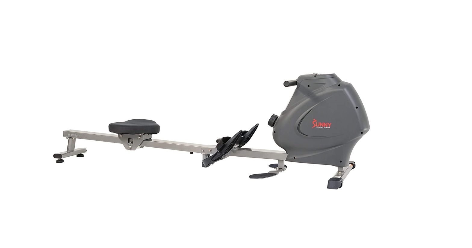
SUNNY Multifunction SPM Magnetic Rowing Machine SF-RW5941 User Manual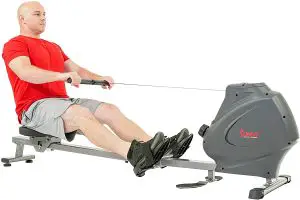
IMPORTANT! Please retain owner’s manual for maintenance and adjustment instructions. Your satisfaction is very important to us, PLEASE DO NOT RETURN UNTIL YOU HAVE CONTACTED US: [email protected] or 1- 877 – 90SUNNY (877-907-8669).
IMPORTANT SAFETY INFORMATION
We thank you for choosing our product. To ensure your safety and health, please use this equipment correctly. It is important to read this entire manual before assembling and using the equipment. Safe and effective use can only be achieved if the equipment is assembled, maintained, and used properly. It is your responsibility to ensure that all users of the equipment are informed of all warnings and precautions.
- Before starting any exercise program, you should consult your physician to determine if you have any medical or physical conditions that could put your health and safety at risk or prevent you from using the equipment properly. Your physician’s advice is essential if you are taking medication that affects your heart rate, blood pressure, or cholesterol level.
- Be aware of your body’s signals. Incorrect or excessive exercise can damage your health. Stop exercising if you experience any of the following symptoms: pain, tightness in your chest, irregular heartbeat, shortness of breath, lightheadedness, dizziness, or feelings of nausea. If you do experience any of these conditions, you should consult your physician before continuing with your exercise program.
- Keep children and pets away from the equipment. The equipment is designed for adult use only.
- Use the equipment on a solid, flat level surface with a protective cover for your floor or carpet.To ensure safety, the equipment should have at least 2 feet (60 CM) of free space all around it.
- Ensure that all nuts and bolts are securely tightened before using the equipment. The safety of the equipment can only be maintained if it is regularly examined for damage and/or wear and tear.
- Always use the equipment as indicated. If you find any defective components while assembling or checking the equipment, or if you hear any unusual noises coming from the equipment during exercise, discontinue use of the equipment immediately and do not use until the problem has been rectified.
- Wear suitable clothing while using the equipment. Avoid wearing loose clothing that may become entangled in the equipment.
- Do not place fingers or objects into the moving parts of the equipment.
- The maximum weight capacity of this unit is 285 pounds (130 KG).
- The equipment is not suitable for therapeutic use.
- To avoid bodily injury and/or damage to the product or property, proper lifting and moving are required.
- Your product is intended for use in cool and dry conditions. You should avoid storage in extreme cold, hot or damp areas as this may lead to corrosion and other related problems.
- This equipment is designed for indoor and home use only; it is not intended for commercial use.
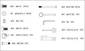
HARDWARE PACKAGE
PARTS LIST
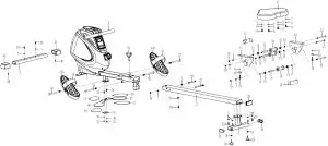 EXPLODED DIAGRAM 1
 EXPLODED DIAGRAM 2
|
No. |
Description | Spec. | Qty. |
| 1 | Main Frame |
1 |
|
|
2 |
Sliding Rail | 1 | |
| 3 | Front Stabilizer |
1 |
|
|
4 |
Rear Stabilizer | 1 | |
| 5 | Handlebar |
1 |
|
|
6 |
Seat | 1 | |
| 7 | Washer | φ8*φ16*1.5 |
15 |
|
8 |
Spring Washer | φ8 | 4 |
| 9 | Bolt | M8*20 |
4 |
|
10 |
Right Seat
Supporting Board |
1 |
|
|
11 |
Left Seat
Supporting Board |
1 | |
| 12 | U Shape Bracket |
2 |
|
|
13 |
Bolt | M8*125 | 3 |
| 14 | Spacer | φ15*φ8*4 |
6 |
|
15 |
Bearing | 608 | 6 |
| 16 | Wheel | φ39*92 |
3 |
|
17 |
Casing Pipe for
Idler Wheel |
φ12*φ9*78 | 3 |
| 18 | Nut | M8 |
4 |
|
19 |
Adjusting Screw | M6*36 | 4 |
| 20 | U Shape Baffle |
4 |
|
|
21 |
Nut | M6 | 6 |
| 22 | Screw | M8*16 |
4 |
|
23 |
End Cap | 2 | |
| 24 | Nut | M8 |
2 |
|
25 |
Foot Pad | 2 | |
| 26 | Square Plug |
1 |
|
|
27 |
Pull Pin | φ8.0*106 | 1 |
| 28 | Bolt | M8*102 |
1 |
|
29 |
Limit Mat | φ22*16 | 1 |
| 30 | Screw | M6*20 |
1 |
|
31 |
Knob | M16*1.5*43.5 | 1 |
| 32 | Bolt | M12*160 |
4 |
|
33L/R |
Pedal L/R | 2 | |
| 34 | Pedal Strap |
2 |
|
|
35 |
Screw | M8*15 | 2 |
| 36 | Left End Cap |
1 |
|
|
37 |
Right End Cap | 1 | |
| 38 | Screw | ST4.2*20 |
8 |
|
39 |
End Cap | 1 | |
| 40 | Round End Cap |
2 |
|
|
41 |
Foam Grip | φ27*φ33*214 | 2 |
| 42 | Nut | M10*1.0*9 |
4 |
|
43 |
Nut | M10*1*B5 | 4 |
| 44 | Inertial Wheel |
1 |
|
|
45 |
Bolt | M6*12 | 4 |
| 46 | Washer | φ12*φ6.5*1.5 |
6 |
|
47 |
Shaft Snap Ring | φ10*1.0 | 4 |
| 48 | Belt Pulley Shaft | φ10*87*M6 |
2 |
|
49 |
Bearing | 6000 | 4 |
| 50 | Mesh Belt Pulley | φ45*35 |
2 |
|
51 |
Washer | φ14*φ10.2*0.5 | 2 |
| 52 | Bolt | M5*10 |
3 |
|
53 |
Handle Guide | 1 | |
| 54 | Sensor Wire |
1 |
|
|
54A |
Sensor Wire A | 1 | |
| 54B | Sensor Wire B |
1 |
|
|
55 |
Volute Spring
Complete Set |
|
1 |
| 56 | Mesh Belt |
1 |
|
|
57 |
Belt | 220PJ | 1 |
| 58 | Tension Control
Knob |
|
1 |
|
59 |
Washer | φ5 | 1 |
| 60 | Screw | M5*12 |
1 |
|
61 |
Left Cover | 1 | |
| 62 | Right Cover |
1 |
|
| 63 | Water Bottle Holder |
1 |
|
|
64 |
Screw | ST4.2*15 | 1 |
| 65 | Clip |
2 |
|
|
66 |
Left Foot Pad | 1 | |
| 67 | Right Foot Pad |
1 |
|
|
68 |
Screw | ST4.2*25 | 7 |
| 69 | Cover Fixed Column |
1 |
|
|
70 |
Computer | 1 | |
| 70A | Computer Wire A |
1 |
|
|
70B |
Computer Wire B |
1 |
|
|
71 |
Battery |
2 |
|
|
72 |
Bolt | M5*15 | 2 |
| 73 | Spanner | S10, 13, 14, 15 |
1 |
|
74 |
Spanner | S10, 13, 17, 19 | 1 |
| 75 | Allen Wrench | S6 |
1 |
|
76 |
Bolt | M6*15 | 2 |
| 77 | Left Anti-slip Mat |
2 |
|
|
78 |
Right Anti-slip Mat | 2 | |
| 79 | Bottom Fixed Plate |
1 |
Ordering Replacement Parts (U.S. and Canadian Customers only)
Please provide the following information in order for us to accurately identify the part(s) needed:
- The model number (found on cover of manual)
- The product name (found on cover of manual)
- The part number found on the “EXPLODED DIAGRAM” and “PARTS LIST” (found near the front of the manual)
Please contact us at [email protected] or 1- 877 – 90SUNNY (877-907-8669).
ASSEMBLY INSTRUCTIONS
We value your experience using Sunny Health and Fitness products. For assistance with parts or troubleshooting, please contact us at [email protected] or 1-877-90SUNNY (877-907-8669).
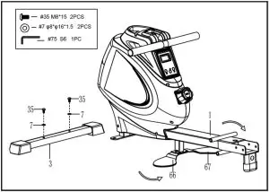
STEP 1:
Attach the Front Stabilizer (No. 3) to the Main Frame (No. 1) using 2 Screws (No. 35) and 2 Washers (No. 7). Tighten and secure with Allen Wrench (No. 75).Open the Left & Right Foot Pads (No. 66 & No. 67) as indicated by the arrow.
STEP 2:
Insert 2 Bolts (No. 32) through the Pedals L/R (No. 33L/R) into the upper hole at position A of the Main Frame (No. 1). Tighten with Spanner (No. 74).
Insert 2 Bolts (No. 32) into the bottom hole at position B of the Main Frame (No. 1). Tighten with Spanner (No. 74).
NOTE: The Pedals L/R (No. 33L/R) should rest on the bottom Bolts (No. 32) at position B.

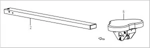
STEP 3:
Slide the Seat (No. 6) into the Sliding Rail (No. 2).
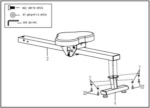
STEP 4:
Attach the Rear Stabilizer (No. 4) to the Sliding Rail (No. 2) using 4 Screws (No. 22) and 4 Washers (No. 7). Tighten and secure with Allen Wrench (No. 75).
STEP 5:
Attach the Sliding Rail (No. 2) to the Main Frame (No. 1) with 1 Bolt (No. 28), 2 Washers (No. 7) and 1 Nut (No. 18). Tighten and secure with Allen Wrench (No. 75) and Spanner (No. 73).
Then screw Knob (No. 31) to tighten the Sliding Rail (No. 2). Next insert the Pull Pin (No. 27).
The assembly is complete!

ADJUSTMENTS & USAGE GUIDE
CAUTION! Moving parts, such as the seat, can cut and crush. Keep hands clear of the sliding rail during use!
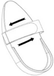 |
PEDAL STRAP ADJUSTMENT
The pedal strap is adjustable and can be personalized to fit the user’s foot size. |
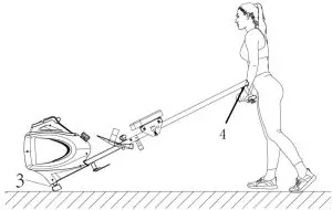 |
MOVING THE ROWER
To move the rower, lift the Rear Stabilizer (No. 4) up until the transportation wheels on the Front Stabilizer (No. 3) touch the ground. With the wheels on the ground, you can transport the rower to the desired location with ease. |
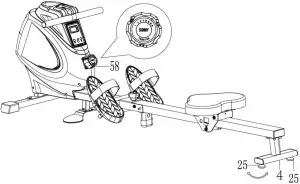 |
ADJUSTING THE BALANCE AND RESISTANCE
Adjust the Foot Pads (No. 25) on the Rear Stabilizer (No. 4) of the rower if the rower is unbalanced during use. Turn the Tension Control Knob (No. 58) clockwise to increase the level of resistance. Turn the Tension Control Knob (No. 58) counter-clockwise to decrease the level of resistance. Tension levels are set at Level 1 being the lowest and Level 16 being the highest. |
BATTERY INSTALLATION & REPLACEMENT
BATTERY INSTALLATION
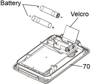
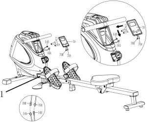
- Press the buckle on the bottom of Computer (No. 70), then remove Computer (No. 70) from Main Frame (No. 1). Disconnect the Sensor Wires A & B (No. 54A & No. 54B) and the Computer Wires A & B (No. 70A & No. 70B), then open the velcro above the battery case on the back of the Computer (No. 70).
- Take out 2pcs AAA batteries from the manual bag. Install the 2pcs AAA batteries into the battery case on the back of the Computer (No. 70), then cover with the velcro. Connect the Sensor Wire A (No. 54A) with Computer Wire B (No. 70B), and connect Sensor Wire B (No. 54B) with Computer Wire A (No. 70A). Press the buckle on the bottom of Computer (No. 70) and put the Computer (No. 70) back onto the Main Frame (No. 1). Pay attention to the battery + and – poles before installing.
The installation is complete!
BATTERY REPLACEMENT
- Press the buckle on the bottom of Computer (No. 70), then remove Computer (No. 70) from Main Frame (No. 1). Disconnect the Sensor Wires A & B (No. 54A & No. 54B) and the Computer Wires A & B (No. 70A & No. 70B), then open the velcro above the battery case on the back of the Computer (No. 70).
- Take out the 2pcs old AAA batteries from the battery case and install 2pcs new AAA batteries into the battery case on the back of the Computer (No. 70), then cover with the velcro. Connect the Sensor Wire A (No. 54A) with Computer Wire B (No. 70B), and connect Sensor Wire B (No. 54B) with Computer Wire A (No. 70A). Press the buckle on the bottom of Computer (No. 70) and put the Computer (No. 70) back onto the Main Frame (No. 1). Pay attention to the battery + and – poles before installing.
The replacement is complete!
NOTE: Always change both batteries at the same time. Do not mix battery types and do not mix old and new batteries. Dispose batteries according to your state and regional guidelines.
STORAGE GUIDE
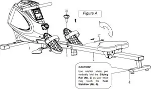
When not in use, you can save space by folding the Sliding Rail (No. 2).
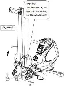
Disassemble Knob (No. 31) and pull out the Pull Pin (No. 27). Fold the Sliding Rail (No. 2) to vertical angle (Figure A).
SAFETY NOTE: the seat will glide down when folding the sliding rail.
Reinsert Pull Pin (No. 27) into the hole on the Main Frame (No. 1), then tighten Knob (No. 31) to Main Frame (No. 1).
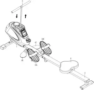
USING THE MACHINE
The Multifunction SPM Magnetic Rowing Machine lets you work out in multiple ways. You can use it as a traditional rowing machine or use it to do upper body strength exercises.
When using it as a rowing machine, make sure to put your feet in the Pedals (No. 33L/R) and use the straps.
When using it to do upper body exercises, adjust the Pedals (No. 33L/R) to suitable position. Stand on the Left & Right Foot Pads (No. 66 & No. 67). Pull on the Handlebar (No. 5) to do the exercises.
EXERCISE COMPUTER
FUNCTION KEYS
MODE: To select your specification mode and/or turn on computer.SET: To set a value of Time, Count, or Calories (when not in Scan mode).RESET: Press to reset Time, Count, or Calories. Press and hold for about 3 seconds to reset all values, except Total Count.
FUNCTIONS AND OPERATIONS
AUTO ON/OFF: The power will turn off automatically once there is no activity for 4 minutes. The computer will reactivate once the machine is put into motion or when a computer button is pressed.SCAN: Press MODE button until SCAN appears. The computer will rotate through the four functions in the following order: TIME, COUNT, TOTAL COUNT, and CALORIES. Each function will be held for 6 seconds.TIME: Counts the total time elapsed during your current workout.COUNT (CNT): Counts the number of rowing strokes from your current workout.TOTAL COUNT (TOTAL CNT): Counts the total amount of strokes from the first use.CALORIES (CAL): Counts the total calories burned from current workout.
COUNTDOWN:You can set the value of Time, Count or Calories to countdown.
- Press MODE to select a function. Make sure you are not in SCAN mode.
- Press SET to select a value you want. You can press RESET to clear the value.
- When the display stops flashing, start rowing and the machine will start to countdown.
BATTERY: This computer uses two AAA batteries. If the display appears incorrectly or becomes difficult to read, please install new batteries. Always change both batteries at the same time. Do not mix battery types and do not mix old and new batteries. Dispose batteries according to your state and regional guidelines.
SPECIFICATIONS
|
FUNCTIONS |
SCAN |
Every 6 seconds |
|
TIME |
0:00~99:59 (Minute: Second) | |
| COUNT |
0~9999 Count |
|
|
CALORIES |
0.0~9999 Kcal | |
| TOTAL COUNT |
0~9999 Count |
|
|
BATTERY TYPE |
(2) Two AAA or UM-4 | |
|
OPERATING TEMPERATURE |
0°C ~ 40°C |
|
| STORAGE TEMPERATURE |
-10°C ~ 60°C |
CONNECT WITH US
FOR FITNESS ARTICLES, VIDEOS & WORKOUTS

 @SUNNYHEALTHANDFITNESS
 @SUNNYHEALTHFITNESS
 @SUNNYHEALTHFIT
![]() /SUNNYHEALTHFITNESS
/SUNNYHEALTHFITNESS
 /SUNNYHEALTHANDFITNESS
 report this ad
[xyz-ips snippet=”download-snippet”]