Instruction Manual

SunTouch SunStat Command
Features:
- Floor temperature control with optional air sensing mode
- Touchscreen display with multiple color themes
- Thin profile with removable, paintable beauty ring
- Easy to use programs and scheduling
- Home automation system tie-in
- Comprehensive help screens
- Three-Year warranty
 Warning
Please be aware local codes may require this control to be installed or connected by an electrician.
This device complies with Part 15 of the FCC Rules and with Industry Canada license-exempt RSS standard(s). Operation is subject to the following two conditions: (1) this device may not cause harmful interference, and (2) this device must accept any interference received, including interference that may cause undesired operation.
Warning
Read this manual BEFORE using this equipment.
Failure to read and follow all safety and use information can result in death, serious personal injury, property damage, or damage to the equipment.

Keep this manual for future reference.
Important Safety Information
This is a safety-alert symbol. The safety-alert symbol is shown alone or used with a signal word (DANGER, WARNING, or CAUTION), a pictorial and/or a safety message to identify hazards.
When you see this symbol alone or with a signal word on your equipment or in this manual, be alert to the potential for death or serious personal injury.
![]() This pictorial alerts you to electricity, electrocution, and shock hazards.
This pictorial alerts you to electricity, electrocution, and shock hazards.
Warning: This symbol identifies hazards which, if not avoided, could result in death or serious injury.
Caution: This symbol identifies hazards which, if not avoided, could result in minor or moderate injury.
Notice: This symbol identifies practices, actions, or failure to act, which could result in property damage or damage to the equipment.
Box Contents
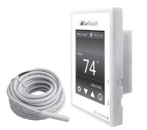
- SunStat Command Thermostat
- Floor sensor
- Screwdriver
- Installation manual
- 2 machine screws
- 5 wire nuts
Items Needed
- Electrical box (must be UL Listed and proper size)
- Wire nuts (must be UL Listed and proper size)
- Flexible or rigid conduit (if required, must be UL Listed and proper size)
- 12-guage or 14-guage electrical wiring cable (UL Listed)
- Nail plate
- Hot glue gun and hot glue
Location
- Thermostat is designed for indoor dry location only.
- Do not install where there is a draft, direct sun, hot-water piping, ducting or other cause for inaccurate temperature readings.
- Do not install where there is electrical interference from equipment, appliances, or other sources.
- Install away from all water sources such as sinks and at least 4′ (1.2 m) away from showers and bathtubs.
- Consider easy access for wiring, viewing, and adjusting.
- Install at a suitable height, normally about 4-1/2′ to 5′ (1.4 m to 1.5 m) from the floor.
Specifications:
- Power supply: 120/240 V (ac), 60 Hz, 3 watts
- Maximum load : 15 amps, resistive
- Maximum power : 1800 watts at 120 VAC3600 watts at 240 VAC
- GFCI: Class A (5 milliamp trip)
- Approvals: UL 943, UL 873, UL 991, FCC Meets Class B: ICES-003 & FCC Part 15B
- Ambient conditions: 32 to 86°F (0 to 30°C), <90% RH non-condensing
- Floor Sensor: Thermistor, 10k NTC type, 300 V jacketed cable, 15′ long

Installation
Warning
Installation must be performed by qualified persons, in accordance with local codes, ANSI/NFPA 70 (NEC Article 424) and CEC Part 1 Section 62 where applicable. Prior to installation, please consult the local codes in order to understand what is acceptable. To the extent this information is not consistent with local codes, the local codes should be followed. Regardless, electrical wiring is required from a circuit breaker or other electrical circuit to the control. It is recommended that an electrician perform these installation steps. Please be aware local codes may require this product to be installed by an electrician.
The following cautions must be observed:
NEVER forget to install the floor sensor included with the thermostat.NEVER put the system into full operation until the tile or flooring installer verifies all cement materials are fully cured (typically two to four weeks after installation).ALWAYS use copper supply conductors to the thermostat. Do not use aluminum.ALWAYS wire all circuits as Class 1, electric light & power circuits.ALWAYS wire all circuits with insulation rated 600V minimum.ALWAYS mount this control to a grounded electrical box.ALWAYS use power supply wires suitable for at least (194°F) 90°C.ALWAYS seek help if a problem arises. If ever in doubt about the correct installation procedure to follow, or if the product appears to be damaged, the factory must be called before proceeding with the installation.
Warning
![]() To prevent the risk of personal injury and/or death, make sure power is not applied to the product until it is fully installed and ready for final testing. All work must be done with power turned off to the circuit being worked on. To reduce the risk of electric shock, do not connect to a circuit operating at more than 150 V to ground.
To prevent the risk of personal injury and/or death, make sure power is not applied to the product until it is fully installed and ready for final testing. All work must be done with power turned off to the circuit being worked on. To reduce the risk of electric shock, do not connect to a circuit operating at more than 150 V to ground.
Power Supply
Pull power supply wiring to the control location.
- Leave about 6 to 8″ (15 to 20 cm) of wire for connections.
- This wiring should be size 12 or 14 AWG, in compliance with local code requirements.
- A qualified person should run a dedicated circuit from the main circuit breaker panel to the control location. If a dedicated circuit is not possible, it is acceptable to tap into an existing circuit. However, there must be enough capacity to handle the load (amps) of the floor heating system being installed, and any appliance likely to be used on the circuit such as a hair dryer or vacuum cleaner.
- Avoid circuits that have ballasted lighting, motors, exhaust fans, or hot tub pumps to reduce the likelihood of interference.
- The circuit breaker should be rated 20 amps for total circuit loads up to 15 amps. A 15-amp circuit breaker may be used for total circuit loads up to 12 amps.
- A GFCI (ground-fault circuit interrupter) or AFCI (arc-fault circuit interrupter) type circuit breaker may be used, but is not necessary.
Warning
Make sure 120 VAC is supplied to 120 VAC cables and 240 VAC is supplied to 240 VAC cables. Otherwise, dangerous overheating and a fire hazard could result. Do not exceed 15-amps on this control.
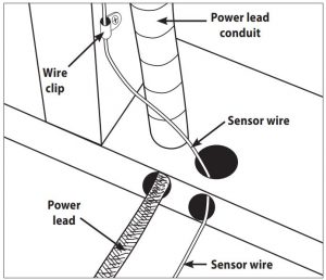
Bottom Plate Work
- Drill or chisel holes at the bottom plate as indicated. One hole is for routing the power lead conduit and the other is for the thermostat sensor. These holes should be directly below the electrical box(es).

SunStat Sensor Installation
- The SunStat sensor can be installed with or without electrical conduit depending on code requirements. Conduit is recommended for added protection against nails and screws.
- Do not place the sensor in the same conduit as the power leads to avoid possible interference. Open a separate knockout in the bottom of the thermostat box. Feed the sensor (and conduit, if used) through the knock-out, down through the cut-out in the bottom plate, and out into the floor where the heating cable will be installed.
- If the sensor wire needs to be secured to the wall stud, wait until after the wire or mat and sensor are completely installed on the floor.
- At the sensor location, measure at least 1′ into the heated area. Mark the spot where the sensor will be attached to the floor. Be sure to place the sensor exactly between two of the heating wires. Ensure the sensor wire does not cross over any heating wires.
- Do not locate the sensor outside the heating area or in a gap between heating wires that is wider than the rest of the floor. Do not locate the sensor where direct sun, hot-water piping, heat duct, or lighting below will cause inaccurate temperature reading. Do not locate the sensor where an insulating item such as a rug is likely to be placed.
- To make sure the sensor tip does not create a high spot in the floor, it may be necessary to chisel a channel into the floor and lay the sensor tip into the channel. Hot glue the tip into place.
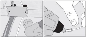
- Do not cut the sensor wire or remove the black cable protector. Strip the wire ends to 1/8″ long.
Floor Heating Mat or Cable Power Lead Installation
- The shielded power lead can be installed with or without electrical conduit (recommended for added protection against nails or screws), depending on code requirements.
- Remove one of the knock-outs in the electrical box to route the power lead. If electrical conduit is not required by code, install a wire collar to secure the power leads where they enter the box. If conduit is required by code, install 1/2″ (minimum) conduit from the bottom plate up to the electrical box. For multiple power leads (multiple cables), install 3/4″ conduit.
- Secure a steel nail plate over the cutout in the bottom plate to protect the wires against baseboard nails later.
SunStat Relay Rough-in Wiring
A SunStat Relay C3 is used when more than 15 amps must be controlled by one SunStat thermostat. The SunStat Command is only compatible with the SunStat Relay C3. Do not use other models.
- Pull 18 AWG to 24 AWG 2-conductor shielded wire from the relay location to this control location. The wire may be up to 100′ (30 m) long.
- Strip the wire ends to 1/8″ long. Refer to the instructions provided with the SunStat Relay C3 for additional details.
Home Automation System Rough-in WiringA short or 24 VAC applied between the Away and Com terminal will switch the thermostat between the ‘Away’ temperature and regular operation.
- Pull 18 AWG to 24 AWG 2-conductor shielded wire from the home automation control to this control location.
- Strip the wire ends to 1/8″ long.
Thermostat Wiring
Before connecting the wires to the back of the thermostat, detach the display front from the base.
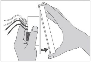
While holding the base section in one hand, pull the lower half of the display front towards you to pivot it away from the base.
Using the wire nuts included with the thermostat:
- Connect the ground wire from the power supply to the ground wire from the floor heating power lead. If the electrical box is metal, use a short length of wire to connect ground wires to the bonding screw.
- Connect the white wire labeled LOAD 2 on the thermostat to the white (or blue for 240 VAC) wire from the heating mat or cable power lead.
- Connect the black wire labeled LOAD 1 on the thermostat to the black wire from the heating mat or cable power lead.
- For 120 VAC connections, the L wire connects to the black (L) hot conductor from the breaker panel. The N wire connects to the white (N) neutral conductor.
- For 240 VAC connections, the L1 connects to one side of the 240 VAC supply from the breaker panel and the L2 to the other.
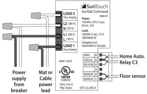
Sensor, relay and home automation connections are made to the terminal block by inserting the wires into the square openings and tightening the screws on the side.
- Connect the sensor wires to the SENSOR terminals on the thermostat. These connections are not polarity sensitive.
- For a SunStat Relay C3, connect 2 wires from the relay to the Com and Relay terminals on the thermostat. Ensure the Com wire at the relay is the same conductor connected to the Com terminal on the thermostat.
- Connect the Away and Com terminals to the appropriate conductors from a home automation system. Refer to the instructions for the home automation control before making these connections.
Warning
Make sure the wire connections are secure by gently tugging on them. Otherwise, arcing could occur, causing dangerous overheating and a possible fire hazard. For added security, overwrap each wire nut connection with electrical tape.
Finish Thermostat Installation
- Ensure all connections are secure.
- Carefully press the wires back into the electrical box. Do not use the control to push them.
- Use the included screws to attach the thermostat base to the electrical box. Do not overtighten.
- When re-attaching the display front, line up the top edge with the base, then rotate the bottom towards the base. Ensure the pins are not bent when connecting.
Notice
Make sure the mortar has had time to fully cure before operating the system for more than a brief test.
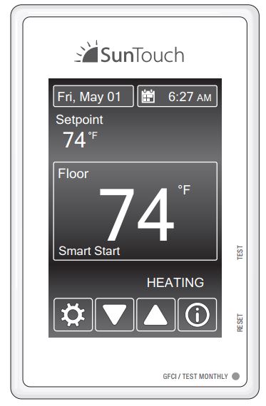
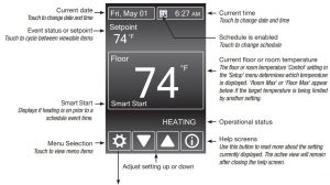
Touch Screen Operation
Touch the time, date or temperature to quickly access settings. Advanced settings are accessed by touching the Setting ![]() button.
button.
Menus
Operation
Power Up
- Switch on the circuit power supply at the breaker.
- The SunStat Command will load stored settings into memory.
Heating OperationBy default, the SunStat Command controls the heating system to maintain a selected floor temperature. This can be switched to room temperature control in the Setup menu. Floor and Room maximum settings are also available to limit temperatures.
GFCI Testing and GFCI Light Operation
- Press the Test button on the GFCI monthly to verify that the GFCI function is operational. The GFCI light will flash red after pressing the Test button. To resume normal operation, press the Reset button.
- If pressing test does not display a flashing red GFCI light, protection is lost and the unit will need replacement.
- If the GFCI light continues to flash after pressing the reset button, protection is lost and the unit will need replacement.
- If the GFCI trips during normal operation, press the Reset button to resume operation. If it trips again, the electric floor heating system should be inspected and tested by a qualified technician.
- If the GFCI light alternates between hi and low brightness during normal operation, the unit has reached end of life and needs to be replaced.
Power Off
- To turn the thermostat off, press the
 button and select from the screen displayed.
 - To restore operation, touch the screen and select the power on button displayed.
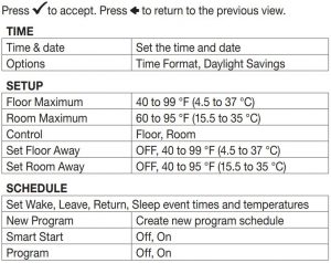
Time Menu
Set the time and date. Select ‘Options’ to access other settings. Time format can be set to a 12- or 24-hr display. Automatic daylight savings time can be set to Off or On.
Setup Menu
Floor or Room Maximum
- Select floor and room maximum temperatures in the Setup menu. These maximum settings are used to to protect temperature-sensitive flooring or prevent space overheating.
- ‘Max’ displays on the screen when the thermostat is limiting the heat output in accordance with the Floor or Room Max setting.
Control
- The ‘control’ setting determines whether the thermostat will operate to maintain a floor temperature, or the room temperature.
Away Settings
- In the Setup menu, the Floor Away or Room Away temperature can be selected, or set to Off (the default).
- A home automation system can enable and disable the Away temperature settings.
Schedule Menu
By default, the thermostat includes one weekday program, a Saturday program and a Sunday program.
- Press to switch between programs.
- To edit the time or temperature for a wake, leave, return, or sleep event, touch the displayed time or temperature. Choose ‘Skip’ to not use an event.
- To divide the schedule by a different grouping of days, select ‘New Program’. You will be prompted to OK deleting the current set of programs.
- Select days to group together in the new programs.
- Every day of the week requires selection on it’s own or within a group before exiting the program settings.
SmartStart
- SmartStart anticipates the time required to provide a scheduled temperature by the start of an event. When Smart Start is set to Off, additional time is required to reach the set temperature.
Program
- Set to On to follow the schedule. Set to Off to use the same temperature all of the time.
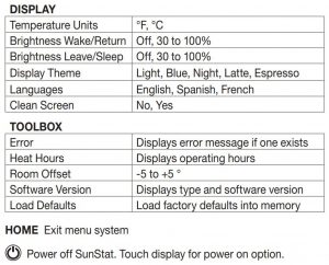
Display Menu
The Display menu allows you to customize preferred display units, brightness, color themes and language options. A Clean Screen feature enables cleaning without affecting operation.
Toolbox Menu
Error
- If there is currently an error, it will display as the first item.
Heat Hours
- Displays the heating duration by day or month.
Room Offset
- This feature can offset operation to account for over or under heating present at the sensor location.
Software Version
- Displays product software version. Load Defaults
- Select ‘yes’ to reload the factory default settings.
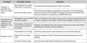
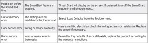
Troubleshooting Guide
It is strongly recommended that a qualified, licensed electrician install the heating cables and related electrical components. If problems with the system arise, please consult the troubleshooting guide below.
Warning
Any electrical troubleshooting work should be performed with the power removed from the circuit, unless otherwise noted.
WARNING: This product contains chemicals known to the State of California to cause cancer and birth defects or other reproductive harm.
For more information: Watts.com/prop65
Limited 3 Year Warranty
Watts Radiant warrants this control (the product) to be free from defect in material and workmanship for a period of (3) years from the date of original purchase from authorized dealers. During this period, Watts Radiant will replace the product or refund the original cost of the product at Watts Radiant’s option, without charge, if the product is proven defective in normal use. Please return the control to your distributor to begin the warranty process.
This limited warranty does not cover shipping costs. Nor does it cover a product subjected to misuse or accidental damage. This warranty does not cover the cost of installation, diagnosis, removal or reinstallation, or any material costs or loss of use.
This limited warranty is in lieu of all other warranties, obligations, or liabilities expressed or implied by the company. In no event shall Watts Radiant be liable for consequential or incidental damages resulting from installation of this product. Some states or provinces do not allow limitations on how long an implied warranty lasts, or the exclusion or limitation of incidental or consequential damages, so the above exclusions or limitations may not apply to you. This warranty gives you specific legal rights and you may also have other rights that vary from state to state.
Watts Radiant Customer SupportUSA Toll-free: (800) 276-2419USA Fax: (417) 864-8161WattsRadiant.comCanada Toll-free: (888) 208-8927Canada Fax: (905) 332-7068Watts.ca
SunTouch Customer SupportUSA Toll-free: (888) 432-8932USA Fax: (417) 831-4067Canada Toll-free: (888) 208-8927Canada Fax: (905) 332-7068Latin America Tel: (52) 81-1001-8600Latin America Fax: (52) 81-8000-7091SunTouch.com
©2015 Watts Water Technologies
References
[xyz-ips snippet=”download-snippet”]