SUPERIOR PUMP 92333, 92301, 92553, 92551 Pedestal Sump Pump Installation Guide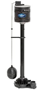
Safety Guidelines
Carefully read, understand and follow all safety instructions in this manual. This is the safety alert symbol. When you see this symbol, look for one of the following signal words.
![]() DANGER Indicates a hazardous situation which, if not avoided, will result in death or serious injury.
DANGER Indicates a hazardous situation which, if not avoided, will result in death or serious injury.
![]() WARNING Indicates a hazardous situation which, if not avoided, could death or serious injury.
WARNING Indicates a hazardous situation which, if not avoided, could death or serious injury.
![]() CAUTION Indicates a hazardous situation which, if not avoided, could minor or moderate injury.
CAUTION Indicates a hazardous situation which, if not avoided, could minor or moderate injury.
NOTICE Indicates important information, that if not followed, may damage to the equipment.
Safety InformationRead these warnings carefully. Know the application and limitations of this pump. Failure to follow these warnings could result in serious bodily injury and/or property damage.
![]() DANGERRISK OF ELECTRICAL SHOCK. This pump is supplied with a grounding conductor and grounding type attachment plug. To reduce the risk of electric shock, be certain that it is connected only to a properly grounded, grounding type receptacle. For added safety, it is highly recommended to connect this pump to a GFCI (Ground Fault Circuit Interrupter) outlet.
DANGERRISK OF ELECTRICAL SHOCK. This pump is supplied with a grounding conductor and grounding type attachment plug. To reduce the risk of electric shock, be certain that it is connected only to a properly grounded, grounding type receptacle. For added safety, it is highly recommended to connect this pump to a GFCI (Ground Fault Circuit Interrupter) outlet.
![]() DANGERRISK OF ELECTRIC SHOCK. Disconnect and lockout power supply before removing old pump or installing or servicing this pump.
DANGERRISK OF ELECTRIC SHOCK. Disconnect and lockout power supply before removing old pump or installing or servicing this pump.
![]() DANGER RISK OF ELECTRIC SHOCK. The motor on this pump is not submersible. DO NOT submerge the motor or allow the motor to be exposed to water. Personal injury or death from electric shock could result.
DANGER RISK OF ELECTRIC SHOCK. The motor on this pump is not submersible. DO NOT submerge the motor or allow the motor to be exposed to water. Personal injury or death from electric shock could result.
![]() WARNING This pump is designed to pump clear water. Do not use this pump to pump chemicals, flammable liquids, sewage or corrosive liquids. You could injure yourself and the pump will fail. Pumping these types of liquids voids the warranty.
WARNING This pump is designed to pump clear water. Do not use this pump to pump chemicals, flammable liquids, sewage or corrosive liquids. You could injure yourself and the pump will fail. Pumping these types of liquids voids the warranty.
![]() WARNING Keep all electrical connections away from wet and moist environments. Wet connections can cause electrical shock resulting in personal injury or death. Do not plug in while standing on a wet floor or in water. If the floor is wet, disconnect power to the pump before walking on floor.
WARNING Keep all electrical connections away from wet and moist environments. Wet connections can cause electrical shock resulting in personal injury or death. Do not plug in while standing on a wet floor or in water. If the floor is wet, disconnect power to the pump before walking on floor.
![]() WARNING Make certain that the electrical outlet is within the reach of the power supply cord. DO NOT USE AN EXTENSION CORD. Extension cords that are too long or too light do not deliver sufficient voltage to the pump motor. More importantly, they present a safety hazard if the insulation were to become damaged or the connection end were to fall into the water.
WARNING Make certain that the electrical outlet is within the reach of the power supply cord. DO NOT USE AN EXTENSION CORD. Extension cords that are too long or too light do not deliver sufficient voltage to the pump motor. More importantly, they present a safety hazard if the insulation were to become damaged or the connection end were to fall into the water.
![]() WARNING All wiring must be performed by a qualified electrician.
WARNING All wiring must be performed by a qualified electrician.
Notice Make sure the sump basin is clear of rocks, sand & debris. Debris can damage or clog the pump which could result in flooding.
![]() WARNING Do not use this pump for potable/drinking water. Use only in applications for which the pump is designed for.
WARNING Do not use this pump for potable/drinking water. Use only in applications for which the pump is designed for.![]() WARNING DO NOT UNDER ANY CIRCUMSTANCES REMOVE THE GROUND PIN. The 3-prong plug must be inserted into a mating 3-prong grounded receptacle. If the installation does not have such a receptacle, it must be changed to the proper type, wired and grounded in accordance with the National Electrical Code and all applicable local codes and ordinances
WARNING DO NOT UNDER ANY CIRCUMSTANCES REMOVE THE GROUND PIN. The 3-prong plug must be inserted into a mating 3-prong grounded receptacle. If the installation does not have such a receptacle, it must be changed to the proper type, wired and grounded in accordance with the National Electrical Code and all applicable local codes and ordinances
![]() CAUTION Do not handle this pump with wet hands or while standing on wet or damp surfaces or in water
CAUTION Do not handle this pump with wet hands or while standing on wet or damp surfaces or in water
![]() CAUTION This pump motor is equipped with an automatic resetting thermal protector and may restart unexpectedly. According to the state of California (Prop 65), this product contains chemicals known to the state of California to cause cancer and birth defects or other reproductive harm.
CAUTION This pump motor is equipped with an automatic resetting thermal protector and may restart unexpectedly. According to the state of California (Prop 65), this product contains chemicals known to the state of California to cause cancer and birth defects or other reproductive harm.![]() CAUTIONIf a flexible discharge hose is used, make sure the pump is secured in the basin to prevent movement. Failure to secure the pump could result in flooding from switch malfunction.
CAUTIONIf a flexible discharge hose is used, make sure the pump is secured in the basin to prevent movement. Failure to secure the pump could result in flooding from switch malfunction.
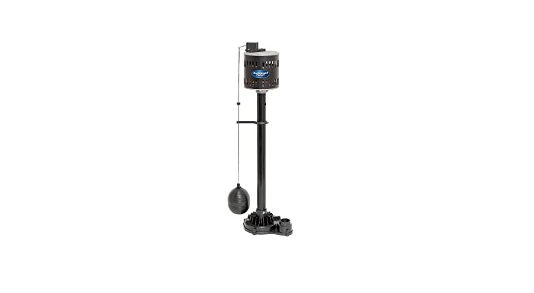
DescriptionThis Pedestal Sump Pump is designed for use in in residential sump basins. The permanent split capacitor motor is equipped with a thermal overload protector for safety. This unit is equipped with a 3-prong grounding type power cord and plug. The vertical style float switch is fully adjustable
Specification
| Model | 92333 | 92301 | 92551 | |
| HP | 1/2 | 1/Z | ||
| Volts | i 20 volt AC | i 20 volt AC | \ 20 volt AC | 120 volt AC |
| Amps | 2.76 | 2.76 | 3.06 | 3.06 |
| Hz | 60 Hz | 60 Hz | 60 Hz | 60 Hz |
| Phase | 1 | 1 | \ | 1 |
| Motor Duty | Continuous | Continuous | Continuous | Continuous |
| Circuit Requirements | T 5 Amp minimum | T 5 Amp minimum | T 5 Amp minimum | \ 5 Amp minimum |
| Discharge Size | 1-\/4” FNPT | 1- \/2 ” FNPT | t- \/2 ” FNPT | 1-\/2 ” FNPT |
| Max. Solids Handling | 318” | 318” | 3/8” | 3/8” |
| Max. Liquid Temperature | 120°F | 180°F | 120°F | 180°F |
| Power Cord Length | \ 0′ | \ 0′ | 10’ | 10′ |
| Float Switch | Vertical (Adjustable) | Vertical (Adjustable) | Vertical (Adjustable) | Vertical (Adjustable) |
| Minimum basin d ameter | 12” | 12” | 12” | 12” |
| Pump Base & Volute | Thermoplastic | Cast Iron | Thermoplastic | Cast Iron |
| Impeller | Stainless Steel | Stainles› Steel | Stainles› Steel | Stainless Steel |
| Motor $haH | PlateJ Steel | Stain|eSs Steel | Plated Steel | Stainless Steel |
| Column | Thermoplastic | Stainless Steel | Thermoplastic | Stainless Steel |
| Float Ball | Thermoplastic | Stainless Steel | Thermoplastic | Stain|ess Steel |
| Float Rod Guide | Thermoplastic | Stain|ess Steel | Thermoplastic | Stainless Steel |
| Float Rod | Galvanized Steel | Stainless Steel | Galvanized Steel | Stainless Steel |
| Fasteners | Sta nless Steel | Stain|eSs Steel | Stainless Steel | Stainless Steel |
| Bearing — Sleeve Bear in9 | Bronze | Bronze | Bronze | Bronze |
| Warranty | \ Year | 3 Years | 1 Year | S Years |
Assembly
FLOAT ASSEMBLY
- Insert the float rod through the hole in the switch arm.
- Push rubber grommet onto the float rod. NOTE: If necessary, use liquid soap to aid in the installation of the grommet.
- Attach float rod guide to the pump column (models 92333 & 92553). On models 92301 & 92551 attach the float road guide to the column but do not fully tighten the fastener at this time.
- Insert the float rod through the float rod guide making sure the float rod is completely vertical and moves up and down freely
- Thread the float ball onto the float rod. If necessary, hold the float rod with pliers to prevent the float rod from turning.
- Once float rod is aligned, secure the float rod guide to the column by completely tightening the fastener. (Models 92301 & 92551 only).
Installation
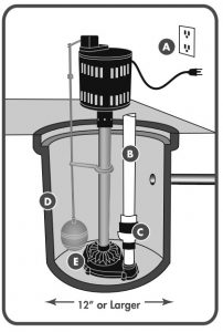
- Place the pump on a solid, level surface in the basin. Use bricks or blocks to raise the pump off the bottom surface. Do not place the pump directly in mud, sand, silt or on rocky surfaces as these materials can clog or cause damage the pump. Do not lower the pump into the basin by the power cord or discharge pipe.
- Position the pump in the basin (D) making sure that the float ball can move up and down freely without coming in contact with the sides of the basin.
- Connect the discharge pipe (B) to the pump discharge.NOTE: If using flexible discharge hose make sure the pump is secure to prevent pump movement and possible interference with the float. 4.
- Connect a check valve (C) (sold separately) to the discharge pipe. Make sure the check valve is installed in the correct direction of flow.
- Connect remaining pipe to the pump. Ensure that the piping will carry the water away from the outside of the foundation.
- A sump basin cover should be installed to prevent debris from falling into the basin.
Operation
- Plug the power cord into a 120 volt grounded outlet. The use of a GFCI is strongly recommended.
- Test your installation by filling the basin with water. Observe the float through at least one complete cycle to ensure it operates freely and does not contact the sides of the basin. If necessary, reposition the pump to ensure proper operation. Make any necessary adjustments to the grommet at this time to adjust the pumping level.
- Your pump motor is thermally protected. The thermal overload protector will automatically shut down the pump in an overheat situation. The pump will reset itself once the pump cools down. This overload is designed as a safety device and it will fail after repeated use
Maintenance
![]() DANGER
DANGER
Risk of electric shock. Always disconnect the power supply before attempting to install, service or perform maintenance on the pump.![]() WARNING All repairs must be made by an authorized service center.
WARNING All repairs must be made by an authorized service center.
- There are no serviceable parts inside the motor. Do not disassemble the motor. If service is required, contact a qualified technician.
- Periodically check the pump intake for obstructions. Clean if necessary.
- Inspect the impeller for signs of wear and obstructions.
- Inspect the power cord for signs of damage or wear. Do not operate the pump if the cord is damaged or worn.
- In applications where the pump may not activate for extended periods of time, it is recommended to cycle the pump at least once per month to ensure the pumping system is working properly when needed.
PerformanceHeight and/or piping restriction will reduce the pump output performance. See the performance chart below to ensure the pump will work in your application. Whenever possible use the same size or larger pipe as the pump discharge for optimum performance. Reducing the pipe size will not harm your pump; it will just reduce the output.
| Gallons per minute at list discharge height | ||||||
| Model | 0’ | 5’ | 10’ | 15’ | 20’ | 25’ |
| 92333,92301 | 50 | 45 | 38 | 35 | 15 | 0 |
| 92553,92551 | 60 | 55 | 45 | 30 | 12 | 5 |
Troubleshooting
| Problem | Possible causes | How to correct |
| If the pump does not start or run | Pump is not plugged in, switch or breaker is off | Plug pump in or turn on switch/ breaker |
| Check for blown fuses or tripped circuit breakers or tripped GFCI outlets | Replace fuse, reset breaker, reset GFCI outlet | |
| Float switch is defective | Check and replace if necessary | |
| Motor thermal protector tripped | Allow pump to cool. Pump will reset automatically | |
| Float is stuck or obstructed | Remove obstruction, adjust float rod guide or position the pump so it will not become stuck | |
| The pump starts and stops too often | Backflow of water from discharge hose/pipe | Install or replace check valve |
| Float is out of adjustment | Adjust grommet on float rod | |
| If the pump runs but moves little or no water | Clogged discharge hose/pipe | Remove clog |
| Frozen discharge hose/pipe | Allow hose/pipe to thaw | |
| Low line voltage | Check wire size and increase if necessary | |
| Check valve is stuck in the closed position | Inspect, repair or replace if necessary | |
| Check valve is installed backwards | Make sure valve is installed in the correct direction of flow | |
| Worn, damaged or clogged pump parts | Inspect for wear, damage or clog and clean or replace if necessary | |
| Discharge head exceeds pump capacity | If pumping height is over 25′, the pump will not move water. See performance chart on page 5 | |
| Pump does not shut off | Float is obstructed or stuck | Remove obstruction, adjust float rod guide or reposition pump |
| Defective Switch | Replace switch |
Replacement parts
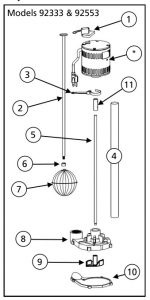
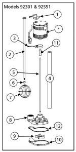
| Ref | Description | 92333 | 92301 | 92553 | 92551 |
| 1. | Switch | 99100 | 99100 | 99100 | 99100 |
| 2. | Float Rod | 99129 | 99131 | 99127 | 99131 |
| 3. | Float Rod Guide | 99126 | 99128 | 99126 | 99128 |
| 4. | Column | 99119 | 99124 | 99121 | 99124 |
| 5. | Motor Drive Shaft | 99113 | 99114 | 99123 | 99114 |
| 6. | Grommet | 99130 | 99130 | 99130 | 99130 |
| 7. | Float Ball | 99132 | 99134 | 99130 | 99134 |
| 8. | Base | 99146 | 99148 | 99145 | 99148 |
| 9. | Impeller | 99116 | 99118 | 99116 | 99118 |
| 10. | Volute | 99140 | 99142 | 99140 | 99142 |
| 11. | Motor shaft coupling | 99112 | 99112 | 99112 | 99112 |
| 12. | Gasket | n/a | 99138 | n/a | 99138 |
LIMITED WARRANTY
PEDESTAL SUMP PUMPS:Superior Pump warrants the products specified in this warranty to be free from defects in material or workmanship for one (1), three (3) or five (5) years from date of purchase depending on model purchased. During the time period and subject to the terms and conditions, Superior Pump will repair or replace to the original user or consumer any portion of this product which proves to be defective due to materials or workmanship. At all times the manufacturer shall have and possess the sole right and option to determine whether to repair or replace defective equipment, parts, or components. The manufacturer has the option to inspect any product returned under warranty to confirm that the warranty applies before repair or replacement under warranty is approved. This warranty sets forth the manufacturer’s sole obligation and purchaser’s exclusive remedy for defective product. Contact Superior Pump for warranty consideration.
WARRANTY PERIOD – PRODUCTS:If, within the duration of product use by the original user, this product proves to be defective due to materials or workmanship, the product shall be repaired or replaced at Superior Pump’s option, subject to the terms and conditions set forth in this warranty statement. Proof of purchase is required for warranty consideration. In the absence of suitable proof of the purchase date, the effective period of this warranty is 12 months from the product’s date of manufacture.
LABOR, ETC. COSTS:Superior Pump shall IN NO EVENT be responsible or liable for the cost of field labor or other charges incurred by any customer in removing and/or affixing any product, part, or component thereof. PRODUCT IMPROVEMENTS: Superior Pump reserves the right to change or improve its products or any portions thereof without being obligated to provide such a change or improvement for units sold and/or shipped prior to such change or improvement.
GENERAL TERMS AND CONDITIONS:This warranty shall not apply to damage due to acts of God, normal wear and tear, normal maintenance services and the parts used in connection with such service, lightning or conditions beyond the control of Superior Pump, nor shall it apply to products which, in the sole judgment of Superior Pump, have been subject to negligence, abuse, accident, misapplication, tampering, alteration; nor due to improper installation, operation, maintenance or storage; nor to excess of recommended maximums as set forth in the instructions. Warranty will be VOID if any of the following conditions are found:
- Product is used for purposes other than those for which it was designed and manufactured
- Product not installed in accordance with applicable codes, ordinances, and good trade practices
- Product connected to voltage other than indicated on nameplate or labels
- Pump exposed to but not limited to the following: sand, gravel, cement, grease, plaster, mud, tar, oil, gasoline, solvents or other abrasive or corrosive substances
- Pump has been used for pumping liquids above 120°F (Models 92333 & 92553) or 180°F (Models 92301 & 92551)
- Pump allowed to operate dry (liquid supply cut off)
DISCLAIMER:Any oral statements about the product made by the seller, Superior Pump, the representatives, or any other parties do not constitute warranties, shall not be relied upon by the user, and are not part of the contract for sale. Seller’s and Superior Pumps only obligation, and buyer’s only remedy, shall be the replacement and/or repair by Superior Pump of the product as described above. NEITHER SELLER NOR SUPERIOR PUMP SHALL BE LIABLE FOR ANY INJURY, LOSS OR DAMAGE, DIRECT, INCIDENTAL OR CONSEQUENTIAL (INCLUDING, BUT NOT LIMITED TO, INCIDENTAL OR CONSEQUENTIAL DAMAGES FOR LOST PROFITS, LOST SALES, INJURY TO PERSON OR PROPERTY, OR ANY OTHER INCIDENTAL OR CONSEQUENTIAL LOSS), ARISING OUT OF THE USE OR THE INABILITY TO USE THE PRODUCT, AND THE USER AGREES THAT NO OTHER REMEDY SHALL BE AVAILABLE TO IT. Before using, the user shall determine the suitability of the product for his/her intended use, and user assumes all risk and liability whatsoever in connection therewith.
THE WARRANTY AND REMEDY DESCRIBED IN THIS LIMITED WARRANTY IS AN EXCLUSIVE WARRANTY AND REMEDY AND IS IN LIEU OF ANY OTHER WARRANTY OR REMEDY, EXPRESSED OR IMPLIED, WHICH OTHER WARRANTIES AND REMEDIES ARE HEREBY EXPRESSLY EXCLUDED, INCLUDING BUT NOT LIMITED TO ANY IMPLIED WARRANTY OF MERCHANTABILITY OR FITNESS FOR A PARTICULAR PURPOSE, TO THE EXTENT EITHER APPLIES TO A PRODUCT SHALL BE LIMITED IN DURATION TO THE PERIODS OF THE EXPRESSED WARRANTIES GIVEN ABOVE. Some states and countries do not allow the exclusion or limitations on how long an implied warranty lasts or the exclusion or limitation of incidental or consequential damages, so the above exclusion or limitations may not apply to you. This warranty gives you specific legal rights, and you may also have other rights which vary from state to state.

[xyz-ips snippet=”download-snippet”]