SUPERMICR Add-On Card for up to Two NVMe SSDs

About this User’s GuideThis user’s guide is written for system integrators, IT technicians, and knowledgeable end users. It provides information for the installation and use of the AOC-SLG3-2M2 expansion card.
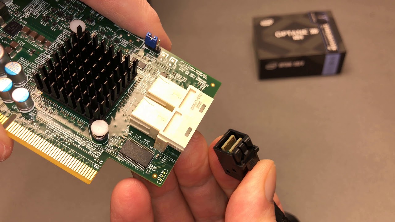
About this Expansion CardThe AOC-SLG3-2M2 is an M.2 SSD carrier card that enables the user to add up to two Non-Volatile Memory express (NVMe) M.2 Solid-State Drives (SSDs). M.2 solid-state technology is an optimized, high-performance scalable storage solution, effectively streamlined for enterprise and client systems that leverage the cutting-edge capabilities of PCI-Express.
An Important Note to the UserAll images and layouts shown in this user’s guide are based upon the latest PCB revision available at the time of publishing. The card you have received may or may not look exactly the same as the graphics shown in this user’s guide.
Returning Merchandise for ServiceA receipt or copy of your invoice marked with the date of purchase is required be-fore any warranty service will be rendered. You can obtain service by calling your vendor for a Returned Merchandise Authorization (RMA) number. When returning the AOC-SLG3-2M2 card to the manufacturer, the RMA number should be prominently displayed on the outside of the shipping carton, and the shipping package is mailed prepaid or hand-carried. Shipping and handling charges will be applied for all orders that must be mailed when service is complete. For faster service, you can also request a RMA authorization online http://www.supermicro.com/RmaForm/.
This warranty only covers normal consumer use and does not cover damages incurred in shipping or from failure due to the alteration, misuse, abuse or improper maintenance of products.During the warranty period, contact your distributor first for any product problems.
Conventions Used in the User’s GuidePay special attention to the following symbols for proper system installation and for safety instructions to prevent damage to the system or injury to yourself:Note: Additional information given for proper system setup.
Contacting Supermicro
Headquarters
Address: Super Micro Computer, Inc. 980 Rock Ave. San Jose, CA 95131 U.S.A.Tel: +1 (408) 503-8000Fax: +1 (408) 503-8008Email: [email protected] (General Information) [email protected] (Technical Support)Website: www.supermicro.com
Europe
Address: Super Micro Computer B.V. Het Sterrenbeeld 28, 5215 ML ‘s-Hertogenbosch, The NetherlandsTel: +31 (0) 73-6400390Fax: +31 (0) 73-6416525Email: [email protected] (General Information) [email protected] (Technical Support) [email protected] (Customer Support)Website: www.supermicro.nl
Asia-Pacific
Address: Super Micro Computer, Inc. 3F, No. 150, Jian 1st Rd. Zhonghe Dist., New Taipei City 235 Taiwan (R.O.C)Tel: +886-(2) 8226-3990Fax: +886-(2) 8226-3992Email: [email protected]
Website: www.supermicro.com.tw
Overview
Congratulations on purchasing your expansion card from an acknowledged leader in the industry. Supermicro products are designed with the utmost attention to detail to provide you with the highest standards in quality and performance. For productsupport and updates, please refer to our website at http://www.supermicro.com.
Technical Specifications
General
- PCIe 3.0 x8 low-profile card
- Ambient operating temperature from 10°C – 55°C
- Supports up to two NVMe M.2 SSDs
OS SupportThe following operating systems and their later versions are supported:
- Windows
- Linux
- VMware
Physical DimensionsCard PCB dimensions: 2.71″ x 5.24″ (H x L)
Hardware Components
Expansion Card Layout and Components

The AOC-SLG3-2M2 Layout
Major Components
The following major components are on the AOC-SLG3-2M2:
- A. M.2 Socket 1
- B. M.2 Socket 2
- C. M.2 Socket 1 Activity LED
- D. M.2 Socket 2 Activity LED
Connectors and LEDs
M.2 SocketsThere are two M.2 sockets on the expansion card.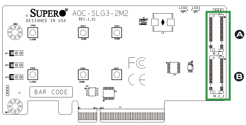
The AOC-SLG3-2M2 NVMe Connectors
A. M.2 Socket 1B. M.2 Socket 2
Activity LEDs
There are two Activity LEDs on the AOC-SLG3-2M2 designated as LED1 and LED2.See the table below for information.
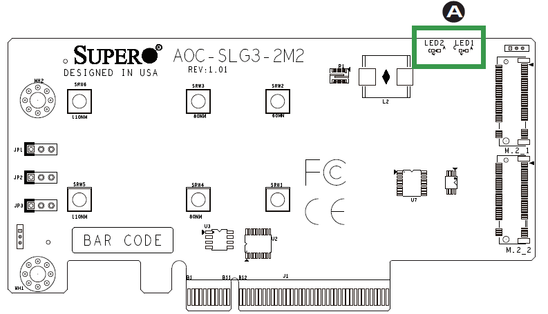
The AOC-SLG3-2M2 LEDs
| Activity LED Status | ||
| LED | Color | Status |
| LED1 | Green | Blinks whenever there is any read or write activity on M.2 Socket 1 |
| LED2 | Green | Blinks whenever there is any read or write activity on M.2 Socket 2 |
Standoffs
The AOC-SLG3-2M2 is designed with movable standoffs which support three different M.2 SSD lengths. Place the standoffs as indicated below:
| M.2 Length | Standoff Positions |
| 22 mm x 110 mm | 1: SRW5 and SRW6 |
| 22 mm x 80 mm | 2: SRW3 and SRW4 |
| 22 mm x 60 mm | 3: SRW1 and SRW2 |
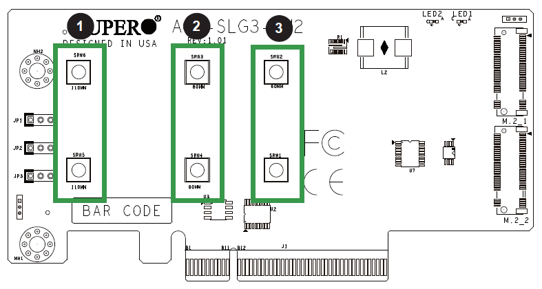
The AOC-SLG3-2M2 Standoff Positions
Front Jumper Locations and Settings
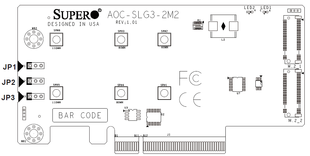
The AOC-SLG3-2M2 Jumpers
Explanation of Jumpers
To modify the operation of the backplane, jumpers can be used to choose between optional settings. Jumpers create shorts between two pins to change the function of the connector. Pin 1 is identified with a square solder pad on the printed circuitboard. Note: On two pin jumpers, “Closed” means the jumper is on and “Open” means the jumper is off the pins.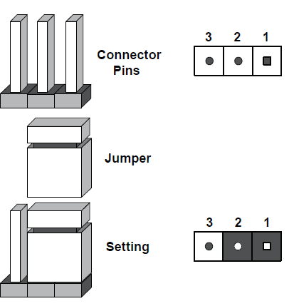
These jumpers are used to configure the SMBus address where the AOC is detected by the BIOS. The default SMBus address is set to “A0”; however, it can also be configured to a different setting to avoid possible address conflict with another device installed on the same SMBus. Please do not change the default setting unless you are explicitly instructed to do so by Supermicro. It should never be changed unless explicitly instructed by Supermicro.
Note: Unless explicitly instructed otherwise by the manufacturer, do not move the jumpers from their default locations. Doing so may disable the jumpers. Jumpers not documented below are unpopulated.
|
SMB Address 1-2=0, 2-3=1 |
|||
| JP3 A2 | JP2 A1 | JP1 A0 | Hex Address |
| 0 | 0 | 0 | A0 |
| 0 | 0 | 1 | A2 |
| 0 | 1 | 0 | A4 |
| 0 | 1 | 1 | A6 |
| 1 | 0 | 0 | A8 |
| 1 | 0 | 1 | AA |
| 1 | 1 | 0 | AC |
| 1 | 1 | 1 | AE |
Installation
Static-Sensitive Devices
Electrostatic Discharge (ESD) can damage electronic com ponents. To avoid dam-aging your expansion card, it is important to handle it very carefully. The following measures are generally sufficient to protect your equipment from ESD.
Precautions
- Use a grounded wrist strap designed to prevent static discharge.
- Touch a grounded metal object before removing the expansion card from the antistatic bag.
- Handle the expansion card by its edges only; do not touch its components or peripheral chips.
- Put the expansion card back into the antistatic bags when not in use.
- For grounding purposes, make sure that your system chassis provides excellent conductivity between the power supply, the case, the mounting fasteners and the expansion card.
Unpacking
The expansion card is shipped in antistatic packaging to avoid static damage. When unpacking your component, make sure you are static protected.Note: To avoid damaging your components and to ensure proper installation, be sure to always connect the power cord last, and always remove it before adding, removing or changing any hardware components
Installing Expansion Cards
The AOC-SLG3-2M2 supports two M.2 SSDs in 60 mm, 80 mm, or 110 mm length. Visit the Supermicro website for a current list of supported M.2 SSDs. Installing Expansion Cards
- Power down the system and remove the power cord from the rear of the power supply.
- Use industry-standard anti-static equipment (such as gloves or wrist strap) and follow the precautions on page 3-1 to avoid damage caused by ESD.
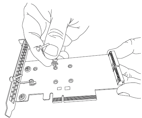
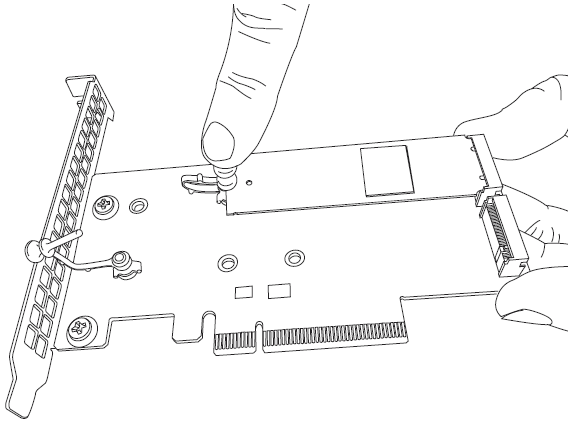
- For each SSD, install the standoff in the appropriate hole that corresponds with the form factor of the SSD to be installed (60 mm, 80mm, or 110 mm length SSDs are supported). Push the plastic standoff until it snaps into the carrier card.
- Insert one or two M.2 SSDs into the slots on the expansion card. Then push it flat against the carrier card and the plastic standoff.Inserting a M.2 SSD into an Expansion Card SlotSecuring the M.2 SSD to the Expansion Card
- Secure each M.2 card by pushing the standoff into place in the mounting hole designated as 60 mm, 80 mm, or 110 mm.The M.2 SSD secured to the Expansion Card
- Simultaneously slide the expansion card bracket into the PCIe slot of the chassis, while plugging the expansion card into the appropriate slot on the motherboard.
- Plug the power cord into the rear of the power supply and power up the system.
 Securing the M.2 SSD to the Expansion Card
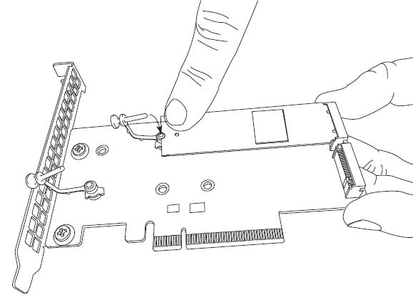
 The M.2 SSD secured to the Expansion Card
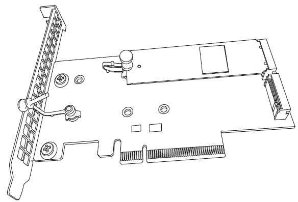

Additional Settings
Depending on the system, motherboard, and BIOS version, the following BIOS settings may be necessary for the proper operation of M.2 NVMe drives:
- Having the CPU IOU settings set to x4x4x4x4 PCIe bifurcation. This option may be found under BIOS Setup -> Advanced -> Chipset Configuration -> North Bridge -> IIO Configuration -> CPU Configuration -> IOU Setting -> x4x4x4x4.
- Having the NVMe Firmware Source set to AMI Native Support. This option may be found under BIOS Setup -> Advanced -> PCIe/PCI/PnP Configuration -> NVMe Firmware Source -> AMI Native Support.
Refer to the applicable system or motherboard user’s manual.
The information in this user’s manual has been carefully reviewed and is believed to be accurate. The vendor assumes no responsibility for any inaccuracies that may be contained in this document, and makes no commitment to update or to keep current the information in this manual, or to notify any person or organization of the updates. Please Note: For the most up-to-date version of this manual, please see our website at www.supermicro.com.
Super Micro Computer, Inc. (“Supermicro”) reserves the right to make changes to the product described in this manual at any time and without notice. This product, including software and documentation, is the property of Supermicro and/or its licensors, and is supplied only under a license. Any use or reproduction of this product is not allowed, except as expressly permitted by the terms of said license.
IN NO EVENT WILL SUPER MICRO COMPUTER, INC. BE LIABLE FOR DIRECT, INDIRECT, SPECIAL, INCIDENTAL, SPECULATIVE OR CONSEQUENTIAL DAMAGES ARISING FROM THE USE OR INABILITY TO USE THIS PRODUCT OR DOCUMENTATION, EVEN IF ADVISED OF THE POSSIBILITY OF SUCH DAMAGES. IN PARTICULAR, SUPER MICRO COMPUTER, INC. SHALL NOT HAVE LIABILITY FOR ANY HARDWARE, SOFTWARE, OR DATA STORED OR USED WITH THE PRODUCT, INCLUDING THE COSTS OF REPAIRING, REPLACING, INTEGRATING, INSTALLING OR RECOVERING SUCH HARDWARE, SOFTWARE, OR DATA.
Any disputes arising between manufacturer and customer shall be governed by the laws of Santa Clara County in the State of California, USA. The State of California, County of Santa Clara shall be the exclusive venue for the resolution of any such disputes. Supermicro’s total liability for all claims will not exceed the price paid for the hardware product.
FCC Statement: This equipment has been tested and found to comply with the limits for a Class A digital device pursuant to Part 15 of the FCC Rules. These limits are designed to provide reasonable protection against harmful interference when the equipment is operated in a commercial environment. This equipment generates, uses, and can radiate radio frequency energy and, if not installed and used in accordance with the manufacturer’s instruction manual, may cause harmful interference with radio communications. Operation of this equipment in a residential area is likely to cause harmful interference, in which case you will be required to correct the interference at your own expense.
California Best Management Practices Regulations for Perchlorate Materials: This Perchlorate warning applies only to products containing CR (Manganese Dioxide) Lithium coin cells. “Perchlorate Material-special handling may apply. See www.dtsc.ca.gov/hazardouswaste/perchlorate”.
The products sold by Supermicro are not intended for and will not be used in life support systems, medical equipment, nuclear facilities or systems, aircraft, aircraft devices, aircraft/emergency communication devices or other critical systems whose failure to perform be reasonably expected to result in significant injury or loss of life or catastrophic property damage. Accordingly, Supermicro disclaims any and all liability, and should buyer use or sell such products for use in such ultra-hazardous applications, it does so entirely at its own risk. Furthermore, buyer agrees to fully indemnify, defend and hold Supermicro harmless for and against any and all claims, demands, actions, litigation, and proceedings of any kind arising out of or related to such ultra-hazardous use or sale.
Manual Revision 1.1Release Date: June 18, 2019Unless you request and receive written permission from Super Micro Computer, Inc., you may not copy any part of this document. Information in this document is subject to change without notice. Other products and companies referred to herein are trademarks or registered trademarks of their respective companies or mark holders.Copyright © 2019 by Super Micro Computer, Inc.All rights reserved.Printed in the United States of America
![]()
References
dtsc.ca.gov/hazardouswaste/perchlorate
P65Warnings.ca.gov
Supermicro SuperBlades, uGPU, AI System, Multi-Node Servers
Supermicro SuperBlades, uGPU, AI System, Multi-Node Servers
RMA Form | RMA Services | Support – Super Micro Computer, Inc.
Supermicro SuperBlades, uGPU, AI System, Multi-Node Servers
[xyz-ips snippet=”download-snippet”]