SureCall Fusion4Home 3.0 Yagi Panel Kit Installation Guide
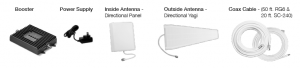
Contents
1. FIND AREA OUTSIDE WITH STRONGEST SIGNAL
Using your phone, identify the outside location with the strongest signal. Generally, this is found on the side facing your nearest cell tower and as high as possible.Note that Bars are not always a reliable measure of signal. The best way to confirm signal coverage is the ability to place and hold a call. For specific dB signal measurements, use the methods below. Note that dB measurements appear as a negative number where the closer to 0, the stronger the signal (eg. -100 dB would be considered a weak signal while -65 dB a strong signal). Apple iPhones: Dial *3001#12345#* and press Call. In the top-left corner, a dB number appears instead of bars. Android devices: download the app “Network Signal Info” in the Google Play store. This signal booster requires a minimum cellular signal reading of -100dB at the location of the outside antenna. Signal between -70dB and -90dB is recommended for best performance. Please note: Signal stronger than -50dB may cause the affected frequency bands to turn off.
2. INSTALL THE OUTSIDE ANTENNA
Outside Antenna Assembly
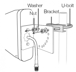
(not included) at the highest possible elevation. The directional Yagi antenna works best when facing the direction of your carrier’s cellular tower. To find the location of your carrier’sclosest cell tower go to www.cellreception.com. To install the outside antenna, assemble the u-bolt, bracket, nuts and washers as shown in the illustration. Keep the connections loose enough to allow the antenna to rotate until the optimum direction is found. Note: The outside antenna may be installed on a variety of pipe angles. Ensure that the mounting area has at least a 12-inch radius clear of obstructions and other radiating elements and orient the antenna vertically with the drip hole at the bottom. Once the outside antenna is secured to a pipe or pole, connect one end of the provided 50 ft. coax cable to the antenna and tighten the connection.
3. INSTALL THE SIGNAL BOOSTER AND INSIDE ANTENNA
Choose a location for mounting the directional panel antenna on vertical surface. The antenna should be at the approximate height of your cell phone when in use and facing a central area where signal is needed. Please note: Be sure to provide enough separation from outside antenna – at least 25 ft. Also, the outside and inside antennas should face away from one another. Using the plate, mark position of desired screw placement and screw mounting plate into place with the slide panel protruding towards you (see panel antenna illustration below). Slide antenna securely onto mounting plate.To install the booster, select a location that is near the inside panel antenna and a working AC outlet*. Use the supplied screws or appropriate screws for surface of mounting location and drill through screw tab holes on booster (see Booster Components Diagram illustration) and mount the booster to a wall. Connect the inside antenna and booster by connecting one end of the provided 20 ft. of coax cable to the inside antenna andthe other end of the cable to the booster port marked “INSIDE” and hand-tighten the connection. Next, connect the outside antenna and booster by connecting the remaining end of the 50 ft. cable leading from the outside antenna to the port of the booster marked “OUTSIDE”.
4. CONNECT POWER
Connect the AC power cord to the booster and plug into a 110V AC power outlet. Once the booster has been completely assembled, turn the booster’s power switch on.Note: If the Power LED does not turn ON or the Alert LEDs continue to flash, see the Troubleshooting section. This booster is rated for 5-15V input voltage. DO NOT use the booster with a higher voltage power supply. This can damage the booster, cause personal injury and void your warranty
CONFIGURE GAIN SETTINGS
The SureCall gain dials should always be at maximum level unless the control light in a specific band is flashing red or flashing red-yellow. In either of these cases, the first action should be to increase the antenna isolation between the inside and outside antenna as much as possible and restart the booster. If the situation continues, you can lower the gain with an attenuator or, as the last resort, reduce the booster gain by 5dB at a time until the control light in the frequency band flashes yellow.
Quick Install Guide
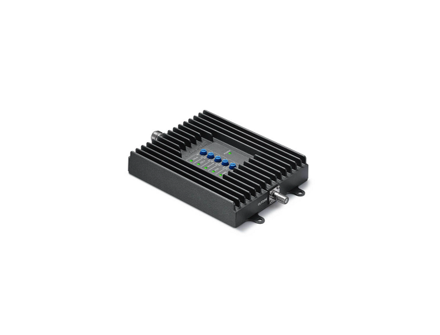
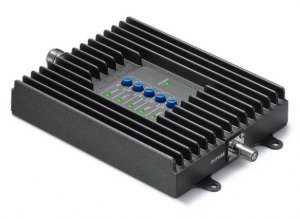
Download the complete manual at www.SureCall.com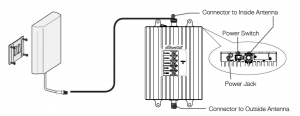 Booster Components Diagram
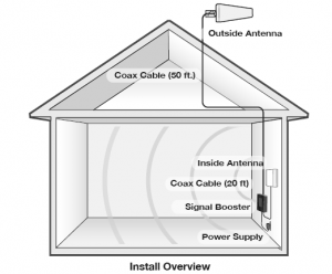
Install Overview
LED Indicators
| LED | LED | |
| Color | Condition | Indication |
| Yellow | Solid | Indicates that the band is Inactive. After a period of time, if there’s no activity the band will go intosleep mode. Light is off while band is active. This is part of normal operation. |
| Yellow | Flashing | Flashing Indicates that the Automatic Gain Control (AGC) is self-adjusting. This is part of normal operation |
| Red | Flashing | Indicates that the booster is receiving too much signal which could cause the affected band to automatically turn off. When this happens:
|
| Yellow/ | Alternately | Oscillation is detected. |
| Red | Flashing | First, try increasing the separation between the inside and outside antennas. If your booster kit uses two directional antennas (example: outside Yagi antenna and inside panel antenna), ensure that they are facing away from one another. If oscillation continues, lower the dB gain in small increments until the light turns off or flashes yellow |
| Red | Solid | Band is off.If a red light has been flashing for an extended time, the band will automatically shut off and display a solid red light.This can also happen when the booster attenuation has been turned all the way down. |
WARNING: Do not attenuate the uplink and downlink dB settings below 35dB. This could cause the affected frequency band to turn off.
If you Want to Improve Coverage
- Find a location that receives a stronger signal and relocate the outside antenna to that location.
- Optimize the Yagi antenna angle.
- Increase the distance between the outside and inside antenna.
- Set each dial on the booster to maximum gain.
Troubleshooting
| Problem | Resolution |
| Signal booster has no power | Connect the power supply to an alternate power source.Verify that the power source is not controlled by a switch that has removed power fromthe outlet.If the POWER LED on the signal booster is OFF, contact tech support at: 1-888-365-6283 or |
| After completing installation,indoor signal coverage has notimproved | (1) Verify that all cable connections are tightly fitted. (2) Try further separating the boosterand antenna. (3) Verify that there is usable signal where the outside antenna is placed. Remember: Bars are not always a reliable measure of signal. The best way to confirmsignal coverage is the ability to place and hold a call. |
Specifications
Fusion4Home 3.0 (US) Fusion4Home 3.0 CA (Canada)
Uplink Frequency Range (MHz):698-716 / 776 – 787 / 824-849 / 1850-1915 / 1710-1755 (G Block IncludedDownlink Frequency Range (MHz): 728-746 / 746 – 757 / 869-894 / 1930-1995 / 2110-2155 (G Block Included)Maximum Gain: 72 dBSupported Standards: CDMA, WCDMA, GSM, EDGE, HSPA+, EVDO, LTE and all cellular standardsInput Impedance: 75Ω donor port / 50Ω server portNoise Figure: 8 dBAC Input: Input AC110V, 60 Hz; Output DC 5-15VMaximum Output Power: 1 Watt EIRPCable: RG6 / SC-240RF Connectors: F Female / N FemalePower Consumption: <15WOperation Temperature: -4º to +158º FCertifications FCC ID: RSNF4HOME
Have questions?
We have answers! Reach out to our US-based support team:Call: 1-888-365-6283Email: Visit: www.surecall.com/support to download the user manual for:» Detailed setup instructions » Troubleshooting tips » Warranty information
3-Year Warranty
Thank you for your SureCall purchase. Please take the time to register your new product at www.surecall.com/activate (US) or www.surecall.com/CA/activate (Canada) SureCall warranties its products for three years from the date of purchase against defects in workmanship and/or materials. Products returned by customers must be in their original, un-modified condition, shipped at the customer’s expense in the original or protective packaging with proof-of-purchase documentation enclosed and a Return Merchandise Authorization (RMA) number printed clearly on the outside of the shipping container. RMA numbers are obtained by contacting Customer Support. This warranty does not apply to any product determined by SureCall to have been subjected to misuse, abuse, neglect, or mishandling that alters or damages the product’s physical or electronic properties. For complete warranty text, including limitations and liability, see the Fusion4Home 3.0 full user manual, available online.
This is a CONSUMER device.
BEFORE USE, you MUST REGISTER THIS DEVICE with your wireless provider and have your provider’s consent. Most wireless providers consent to the use of signal boosters. Some providers may not consent to the use of this device on their network. If you are unsure, contact your provider. In Canada, BEFORE USE you must meet all requirements set out in ISED CPC-2-1-05. You MUST operate this device with approved antennas and cables as specified by the manufacturer. Antennas MUST be installed at least 20 cm (8 inches) from (i.e., MUST NOT be installed within 20 cm of) any person. You MUST cease operating this device immediately if requested by the FCC (or ISED in Canada) or licensed wireless service provider.WARNING: E911 location information may not be provided or may be inaccurate for calls served by using this device. This device may operate in a fixed location only, for in-building use. This device complies with Part 15 of the FCC Rules. Operation is subject to the following two conditions: (1) this device may not cause harmful interference, and (2) this device must accept any interference received, including interference that may cause undesired operation.
Read More About This Manual & Download PDF:
References
[xyz-ips snippet=”download-snippet”]