![]()
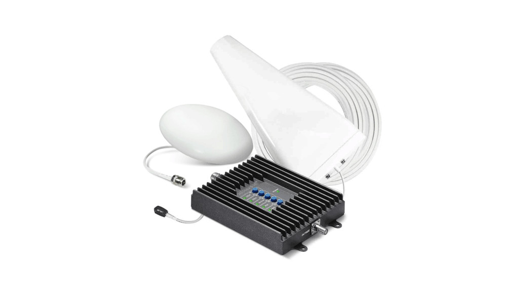
Quick Install GuideSureCall Fusion4Home®Yagi / Dome KitDownload the complete manual at www.SureCall.com
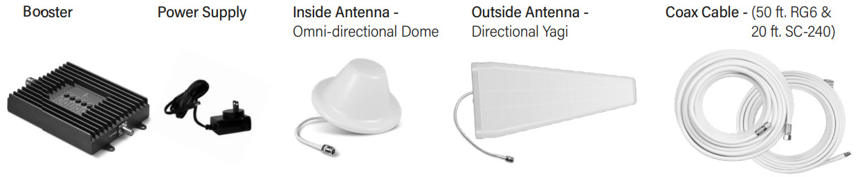
CONTENTS
Before installation, ensure adequate separation between the locations of the outside antenna and inside antenna – at least 25 ft.
FIND THE LOCATION OUTSIDE WITH THE STRONGEST SIGNAL
Using your phone, identify the outside location with the strongest signal. This is generally found on the side facing your nearest cell tower and as high as possible. Capturing the strongest possible signal with your outside antenna will provide the best resulting coverage.Bars are not always a reliable measure of the signal. The best way to confirm signal coverage is the ability to place and hold a call. Putting your phone in Field Test mode will also indicate what level of decibels (dB) your phone is receiving.For dB measurements, use the methods below. Note that dB measurements appear as a negative where a number closer to 0 indicates a better signal (-120 dB indicates no service, while -50 dB would be considered an excellent signal).
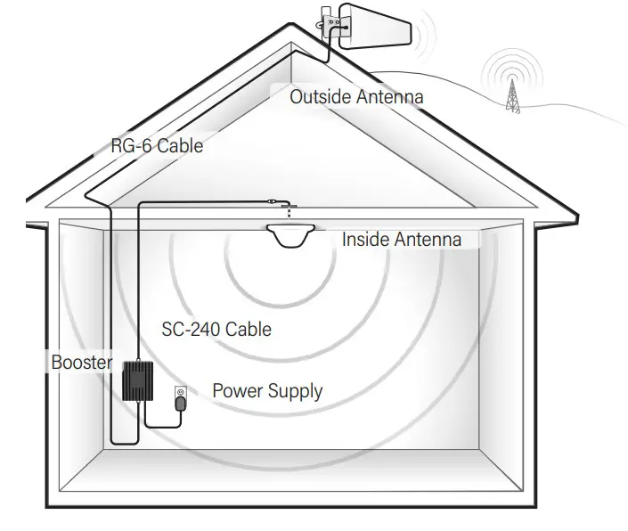
Install Overview
- Apple iPhones: Dial *3001#12345#* and press Call. In the top-left corner, a dB number appears instead of bars.
- Android devices: download the app “Network Signal Info” in the Google Play store.This signal booster requires a minimum cellular signal reading of -100dB at the location of the outside antenna. Also note, signal stronger than -50dB may cause the affected frequency bands to shut off.
INSTALL THE OUTSIDE ANTENNA
Once you have located the area of the strongest signal, mount the antenna to a pole or pipe (not included) at the highest possible elevation. The directional Yagi antenna works best when facing the direction of your carrier’s cellular tower. To find the location of your carrier’s closest cell tower go to www.cellreception.com.To install the outside antenna, assemble the u-bolt, bracket, nuts, and washers as shown in the illustration. Keep the connections loose enough to allow the antenna to rotate until the optimum direction is found.Note: The outside antenna may be installed on a variety of pipe angles. Ensure that the mounting area has at least a 12-inch radius clear of obstructions and other radiating elements and orient the antenna vertically with the drip hole at the bottom. Once the outside antenna is secured to a pipe or pole, connect one end of the provided 50 ft. coax cable to the antenna and tighten the connection.

Have questions?We have answers! Reach out to our US-based support team:Call: 1-888-365-6283Email: [email protected]Visit: www.surecall.com/support to download the user manual for:» Detailed setup instructions» Troubleshooting tips» Warranty information
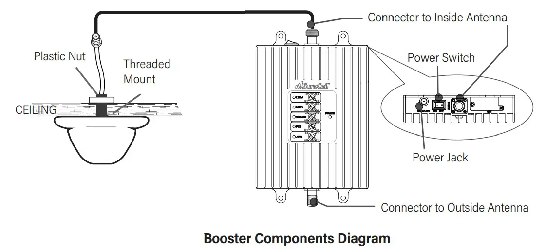
INSTALL THE INSIDE ANTENNA AND BOOSTER
Choose a location central to where the signal is needed with accessible ceiling placement for mounting the dome antenna. Drill a 20 mm diameter hole in the ceiling. The ceiling thickness should not exceed 20 mm.Unscrew fixing nut from antenna and place antenna cable through the ceiling hole. From the crawl space, screw the fixing nut onto the antenna and fasten it around the threaded base.Next, choose a location for the booster that is near a power outlet and within the allowable length of the provided 20 ft cable.Connect the inside antenna and booster using the provided 20 ft. of coax cable to the inside antenna and the other end of the cable to the booster port marked “INSIDE” and hand-tighten the connection.Next, connect the outside antenna and booster by routing the 50 ft. cable leading from the outside antenna to the port of the booster marked “OUTSIDE”.
CONNECT TO POWER AND TURN ON
Connect the AC power cord to the booster and plug it into a 110V AC power outlet. Once the booster has been completely assembled, turn the booster’s power switch on.Note: If the Power LED does not turn ON or the Alert LEDs continue to flash, see the Troubleshooting section. This booster is rated for 5-15V input voltage. DO NOT use the booster with a higher voltage power supply. This can damage the booster, cause personal injury and void your warranty.
CONFIGURE GAIN SETTINGS IF NEEDED
Place a call in the room where the inside antenna is located to confirm that your phone is receiving a boosted signal.Note: Bars are not always a reliable measure of the signal. The best way to confirm signal coverage is the ability to place and hold a call.The dials should always be at maximum level unless the control light for a specific frequency band is flashing red or flashing red-yellow. In either of these cases, the first action should be to increase the antenna isolation between the inside and outside antenna as much as possible and restart the booster.If the situation continues, you can lower the gain in 5dB increments until the control light for the frequency band flashes yellow.
LED Indicators
| Color | Condition | Indication |
| OFF | This is part of a normal operation. Light is off while band is active. | |
|
Yellow |
Solid | This is part of a normal operation. This indicates that the band is Inactive. After a period of time, if there’s no activity the band will go into sleep mode. Light is off while the band is active. |
| Yellow | Flashing | This is part of a normal operation. This indicates that the Automatic Gain Control (AGC) is self-adjusting. |
| Red | Flashing | This indicates that the booster is receiving too much signal which could cause the affected band to automatically turn off. If this happens:
|
| Yellow/ Red | Alternately Flashing | Oscillation is detected.First, try increasing the separation between the inside and outside antennas.If oscillation continues, lower the dB gain in small increments until the light turns off or flashes yellow. |
| Red | Solid | The frequency band is off.If a red light has been flashing for an extended time, the band will automatically shut off and display a solid red light.This can also happen if booster attenuation has been turned all the way down. |
Troubleshooting
| Problem | Resolution |
| Signal booster has nopower | Connect the power supply to an alternate power source.Verify that the power source is not controlled by a switch that has removed power from the outlet.If the POWER LED on the signal booster remains OFF, contact tech support at: 1-888-365-6283 or[email protected] |
| After completingthe installation, indoorsignal coverage has not improved | (1) Verify that all cable connections are tightly fitted. (2) Try further separating the booster and antenna.(3) Verify that there is a usable signal where the outside antenna is placed.i Remember: Bars are not always a reliable measure of the signal. The best way to confirm signal coverage isthe ability to place and hold a call. |
 report this ad
WARNING: Do not attenuate the uplink and downlink dB settings below 35dB. This could cause the affected frequency band to turn off.
Specifications
| Fusion4Home 3.0 / 3.1 | Fusion4Home 3.0 / 3.1 CA (Canada) | |
| Uplink Frequency Range (MHz): | 698-716 / 776-787 / 824-849 / 1850-1915 / 1710-1755 | |
| Downlink Frequency Range (MHz): | 728-746 / 746-757 / 869-894 / 1930-1995 / 2110-2155 | |
| Maximum Gain: | 72 dB | |
| Supported Standards: | CDMA, WCDMA, GSM, EDGE, HSPA+, EVDO, LTE and all cellular standards | |
| Input Impedance: | 75Ω donor port / 50Ω server port | |
| Noise Figure: | 8 dB | |
| AC Input: | Input AC110V, 60 Hz; Output DC 5-15V | |
| Maximum Output Power: | 1 Watt EIRP | |
| Cable: | RG6 / SC-240 | |
| RF Connectors: | F Female / N Female | |
| Power Consumption: | <15W | |
| Operation Temperature: | -4º to +158º F | |
| Certifications | FCC ID: RSNF4HOME / RSNF4HOME3 | IC: 7784A-F4HOME / 7784A-F4HOME3 |
This is a CONSUMER device.BEFORE USE, you MUST REGISTER THIS DEVICE with your wireless provider and have your provider’s consent. Most wireless providers consent to the use of signal boosters. Some providers may not consent to the use of this device on their network. If you are unsure, contact your provider.In Canada, BEFORE USE you must meet all requirements set out in ISED CPC-2-1-05.You MUST operate this device with approved antennas and cables as specified by the manufacturer. Antennas MUST be installed at least 20 cm (8 inches) from (i.e., MUST NOT be installed within 20 cm of) any person.You MUST cease operating this device immediately if requested by the FCC (or ISED in Canada) or a licensed wireless service provider.WARNING: E911 location information may not be provided or may be inaccurate for calls served by using this device.This device may operate in a fixed location only, for in-building use.This device complies with Part 15 of the FCC Rules. Operation is subject to the following two conditions: (1) this device may not cause harmful interference, and (2) this device must accept any interference received, including interference that may cause undesired operation.Fremont, CA 94538 USA | +1-888.365.6283 | [email protected] | www.surecall.com© 2020. All Rights ReservedPart: SC-PolyH-72-YD-Kit UPC: 854328008596Rev1 03.02.20
References
[xyz-ips snippet=”download-snippet”]