![]()
CHANGING YOUR LANDSCAPE SINCE 1945swisherinc.comOWNER’S MANUAL2645RStarting Serial #: L212-261001Plow Blade, 50″
![]() IMPORTANTRead and follow all Safety Precautions and Instructions Before Operating this Equipment.
IMPORTANTRead and follow all Safety Precautions and Instructions Before Operating this Equipment.
SWISHER ACQUISITION INC.1602 CORPORATE DRIVE, WARRENSBURG, MISSOURI 64093PHONE 660-747-8183 FAX 660-747-8650
Made in The USA of the US and Global Parts
LIMITED WARRANTYThe manufacturer’s warranty to the original consumer purchaser is: This product is free from defects in materials and workmanship for a period of one (1) year from the date of purchase by the original consumer purchaser. We will repair or replace, at our discretion, parts found to be defective due to materials or workmanship. This warranty is subject to the following limitations and exclusions:
- Commercial UseThis product is not intended for commercial use and carries no commercial warranty.
- LimitationThis warranty applies only to products that have been properly assembled, adjusted, and operated in accordance with the instructions contained within this manual. This warranty does not apply to any product of Swisher that has been subject to alteration, misuse, abuse of proper assembly or installation, shipping damage, or to normal wear of the product.
- ExclusionsExcluded from this warranty are normal wear, normal adjustments, and normal maintenance.
In the event you have a claim under this warranty, you must return the product to an authorized service dealer. All transportation charges, damage, or loss incurred during transportation of parts submitted for replacement or repair under this warranty shall be borne by the purchaser. Should you have any questions concerning this warranty, please contact us toll-free at 1-800-222-8183. The model number, serial number, date of purchase, and the name of the authorized Swisher dealer from whom you purchased the product will be needed before any warranty claim can be processed.
THIS WARRANTY DOES NOT APPLY TO ANY INCIDENTAL OR CONSEQUENTIAL DAMAGES AND ANY IMPLIED WARRANTIES ARE LIMITED TO THE SAME TIME PERIODS STATED HEREIN FOR ALL EXPRESSED WARRANTIES. Some states do not allow the limitation of consequential damages or limitations on how long an implied warranty may last, so the above limitations or exclusions may not apply to you. This warranty gives you specific legal rights and you may have other rights, which vary from state to state. This is a limited warranty as defined by the Magnuson-Moss Act of 1975.
SAFETY PRECAUTIONS
![]() This Safety Alert Symbol indicates important messages in this manual. When you see this symbol, carefully read the message that follows and be alert to the possibility of personal injury.
This Safety Alert Symbol indicates important messages in this manual. When you see this symbol, carefully read the message that follows and be alert to the possibility of personal injury.
- Read the manual. Learn to operate this machine safely.
- Keep the operating speed LOW!!!!! Do not operate over 5 MPH (8 KPH).
- Allow only responsible adults who are familiar with these instructions to operate this machine. Never allow children to operate this machine.
- Be sure the area is clear of other people before operating. Children are often attracted to the machine and the operating activity. Never assume that children will remain where you last saw them. Keep children under the watchful care of another responsible adult.
- Watch for traffic when operating near or crossing roadways.
- Do not operate the attachment if it has been dropped or damaged in any manner.Repair as necessary.
- Dress properly. Do not operate when barefoot or wearing open sandals.
- Do not operate the machine while under the influence of alcohol or drugs.
- Never tamper with safety devices. Check their proper operation regularly.
- Operate attachments up and down slopes. There is a significant risk of overturns when operating across slopes.
- Stop and inspect the equipment if you strike an object. Repair, if necessary, before restarting.
- Never make adjustments or repairs with the engine running.
- Some components are heavy and may require help when lifting, especially once the parts are assembled.
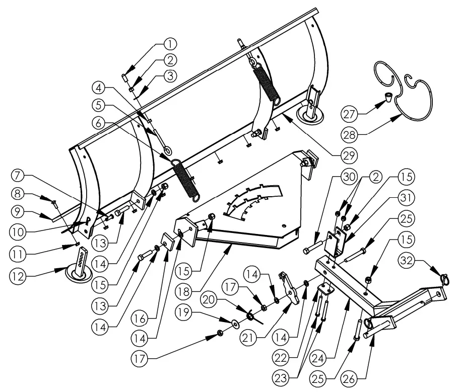
PLOW PARTS DETAIL
Cut Edge 2317 (9) is preinstalled toBlade 2150 (29) using 5/16-18 X 3/4Carriage Bolt 10216 (8) and 5/16-18Serrated Flange Nut NB170 (11).
| Item # | Part # | Description |
| 1 | AS125 | Cap – Round Vinyl, Black |
| 2 | NB182 | Nut – Nyloc 3/8-16 |
| 3 | NB272 | Washer – SAE Flat 3/8 |
| 4 | NB212 | Nut – HNC, 3/8-16 |
| 5 | NB635 | Eyebolt – Turned 3/8-16 X 3 |
| 6 | 2335 | Spring – Tilt |
| 7 | NB300 | Pin – Clevis, 3/8 X 1 1/8 |
| 8 | 10216 | Bolt – Carriage 5/16-18 X 3/4 |
| 9 | 2317* | Edge – Cut, Reversable .25 X 2.5 X 50 |
| 10 | NB127 | Pin – Hair, #39 |
| 11 | NB170 | Nut – Serrated Flange 5/16-18 |
| 12 | 10068* | Skid – Weldment |
| 13 | NB509 | Bolt – 1/2-13 X 2 HCC |
| 14 | NB177 | Washer – Mach 1/2 |
| 15 | NB281 | Nut – Nyloc 1/2-13 |
| 16 | 2331* | Block – Tilt |
| Item # | Part # | Description |
| 17 | NB121 | Nut – Jam Lock, 1/2-13 2-Way |
| 18 | 2323* | Pivot – Weldment |
| 19 | TR150W | Washer – .531 X 1 1/2 X .062 |
| 20 | 2336 | Spring – Pivot |
| 21 | 2319* | Latch – Lever Assembly |
| 22 | 2310* | Bracket – Support; Plow |
| 23 | NB150 | Bolt – 3/8-16 X 3 HCC |
| 24 | 2588* | Mount – Plow Weldment |
| 25 | NB577 | Bolt – 1/2-13 X 3 1/2 |
| 26 | 2642* | Pin – Plow Mount, 3/4 X 12 |
| 27 | H7K | Knob – Rope |
| 28 | H9B | Rope – Red |
| 29 | 2150* | Blade – Rolled Weldment, 50 |
| 30 | NB131 | Bolt – 1/2-13 X 3 HCC |
| 31 | 2327* | Bracket – Lift Assembly |
| 32 | NB506 | Pin – Lynch, 3/16 |
When ordering replacement parts*USE PAINT CODE: GT=GREY TK=BLACK
![]() TO ENSURE PROPER ASSEMBLY, CAREFULLY FOLLOW ALL INSTRUCTIONS LISTED BELOW
TO ENSURE PROPER ASSEMBLY, CAREFULLY FOLLOW ALL INSTRUCTIONS LISTED BELOW
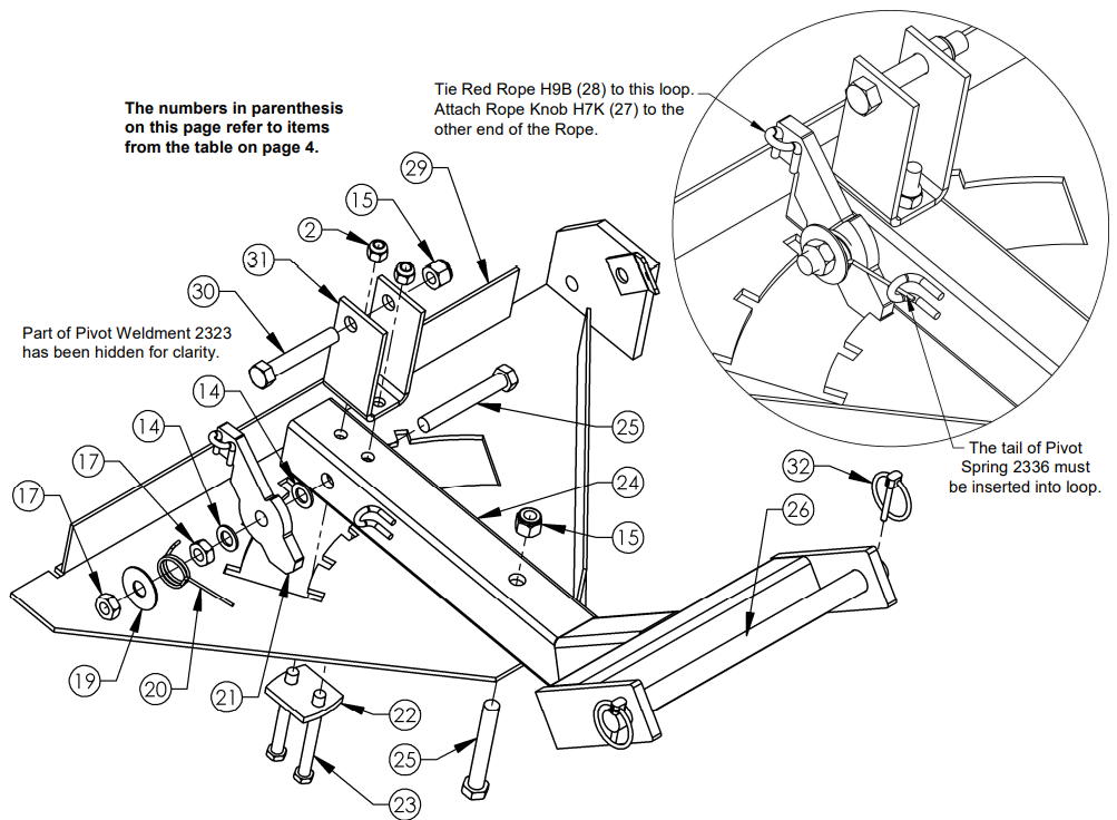
Pivot Latch Assembly
These steps need to be done in sequence:
- Lay parts down in the order they are shown below.
- Slide Plow Mount 2588 (24) into Pivot Weldment 2323 (18) and secure with ½-13 X 3½ Bolt NB577 (25) and ½-13 Nyloc Nut NB281 (15). Do not overtighten; the Plow Mount must be able to pivot freely.
- Assemble the Pivot Latch assembly in the order shown below. The Pivot Latch assembly consists of the following components and is assembled in the following order: ½-13 X 3½ Bolt NB577 (25), Plow Mount 2588 (24), ½ Washer NB177 (14), Lever Latch 2319 (21), ½ Washer NB177 (14), ½-13 Lock Nut NB121 (17), Pivot Spring 2336 (20), 1½ Washer TR150W (19), and Lock Nut NB121 (17). Make sure the tail of the pivot spring is secured into the bent metal loop on the Plow Mount. Do not overtighten; the Lever Latch should be able to pivot freely after being assembled.
- Attach Plow Support Bracket 2310 (22) and Lift Bracket 2327 (31) to Plow Mount 2588 (24) as shown using two NB150 3/8-16 X 3 Bolts (23) and two NB182 3/8-16 Nyloc Nuts (2).
- Insert ½-13 X 3 Bolt NB131 (30) into Lift Bracket 2327 (31) and secure with ½-13 Nyloc Nut NB281 (15). Do not overtighten as this can bend the Lift Bracket. This is where you will attach your winch or manual lift pulley, sold separately.
![]() TO ENSURE PROPER ASSEMBLY, CAREFULLY FOLLOW ALL INSTRUCTIONS LISTED BELOW
TO ENSURE PROPER ASSEMBLY, CAREFULLY FOLLOW ALL INSTRUCTIONS LISTED BELOW
Pivot Mount Assembly
- Connect Skid Weldment 10068 (12) through the channel on the outer right edge of the Blade using Clevis Pin NB300 (7) and Hair Pin NB127 (10) in the order shown below. Repeat for the left side. The height can be adjusted using the holes in the Skid Weldment leg.
- Assemble the Pivot Mount assembly to the Blade using ½-13 X 2 Bolt NB509 (13), ½ Washer NB177 (14), and ½-13 Nyloc Nut NB281 (15) in the order shown below. It is important to ensure the ½ Washer (19) is installed between the Blade and Pivot Mount assembly to allow for the correct rotation of the pivot. Repeat for the other side of the Pivot Mount. Do not overtighten; the Blade should be able to pivot freely after being assembled to the Pivot Mount.
- Assemble the Tilt Block (16) to the left side of the Pivot Mount assembly using ½-13 X 2 Bolt NB509 (13), two NB177 ½ Washers (14), and ½-13 Nyloc Nut NB281 (15). Repeat for the right side of the Pivot Mount assembly. The Tilt Blocks (16) set the vertical “tilt” or rake of the Blade.

![]() TO ENSURE PROPER ASSEMBLY, CAREFULLY FOLLOW ALL INSTRUCTIONS LISTED BELOW
TO ENSURE PROPER ASSEMBLY, CAREFULLY FOLLOW ALL INSTRUCTIONS LISTED BELOW
Tilt Spring Assembly
- Assemble one 3/8-16 Nut NB212 (4) to each Eyebolt NB635 (5).
- Attach one end of Tilt Spring 2335 (6) to the Plow Mount assembly tab and the other end to Eyebolt NB635 (5).
- Assemble Eyebolt NB635 (5) into the hole at the top of the Blade. Secure with 3/8 Washer NB272 (3) and 3/8-16 Nut NB182 (2). Place Vinyl Caps AS125 (1) over the remaining threads of the Eyebolt. Repeat for the other side.

Plow Adjustment & Operation
The tension placed on Tilt Springs 2335 (9) determines the amount of pressure that must be applied to the Blade before it folds over if an obstruction is hit.Tilt Springs 2335 (9) can be adjusted by turning 3/8-16 Nyloc Nut NB182 (4) on the Eyebolts NB635 (8), making adjustments until the Blade does not fold over during normal operation but does fold over if an obstruction is hit. Turn the nut clockwise to tighten the spring and counterclockwise to loosen the spring. Once the desired tension isachieved, lock the position of Eyebolt NB635 (8) using 3/8-16 Nut NB212 (7).To change the Blade angle while operating, come to a stop, turn off the ignition and set the parking brake. Disengage Lever Latch 2840 (26) and rotate the Blade to the desired angle. Engage Lever Latch 2840 (26) making sure it is secured into one of the latch positions of Pivot Weldment 2323 (23).
![]() CHANGING YOUR LANDSCAPE SINCE 1945swisherinc.comOWNER’S MANUAL2645RStarting Serial #: L212-261001Plow Blade, 50″
CHANGING YOUR LANDSCAPE SINCE 1945swisherinc.comOWNER’S MANUAL2645RStarting Serial #: L212-261001Plow Blade, 50″
WHEN ORDERING PARTS, PLEASE HAVE THEFOLLOWING INFORMATION AVAILABLE:* PRODUCT – ________________* SERIAL NUMBER – _______________* MODEL NUMBER – _______________TYPE – _______________* PART NUMBER WITH PAINT CODE* PART DESCRIPTIONTELEPHONE – 1-800-222-8183FAX – 1-660-747-8650
SWISHER ACQUISITION INC.1602 CORPORATE DRIVE, WARRENSBURG, MISSOURI 64093PHONE 660-747-8183 FAX 660-747-8650
Made in The USA of the US and Global Parts
References
[xyz-ips snippet=”download-snippet”]