
Swisher Walk Behind Rough Cut Trail Cutter

Thank you for choosing Swisher’s 24” Walk Behind Rough Cut. Before operating your Walk Behind, please read, understand and follow all of the safety precautions and other instructions explained in this manual. As with all power equipment, lawn mowers can be potentially dangerous if not properly used.
![]() IMPORTANT Read and follow all Safety Precautions and Instructions before operating this equipment.
IMPORTANT Read and follow all Safety Precautions and Instructions before operating this equipment.
SAFETY PRECAUTIONS
 This Safety Alert Symbol indicates important messages in this manual. When you see this symbol, carefully read the message that follows and be alert to the possibility of personal injury.
Read this manual completely. This machine can amputate hands and feet, and throw objects. Failure to observe the following safety instructions could result in serious injury or death.
- Read the manual. Learn to operate this machine safely.
- Always disconnect the spark plug wire and place the wire where it cannot contact the spark plug to prevent accidental starting the engine when setting up, transporting, adjusting or making repairs.
- Keep all shields and guards in place.
- Understand the speed, steering and stability of this machine. Know the positions and operations of all controls before you operate this machine. Check all of the controls in a safe area before starting to work with this machine.
- Allow only responsible adults who are familiar with these instructions to operate this machine.Never allow children to operate this machine.
- Clear the area of objects such as rocks, toys, wire, etc. that can be picked up and thrown by the blade.
- Be sure the area is clear of other people before mowing. Be aware of the mower discharge direction and do not point at anyone. Stop the machine if anyone enters the mowing area. Children are often attracted to the machine and the mowing activity. Never assume that children will remain where you last saw them. Keep children under the watchful care of another responsible adult.
- No riders!
- Do not put hands or feet near or under rotating parts.
- Do not mow in reverse. Always look down and behind before and during backing.
- Turn off the blade when not mowing. Before leaving the machine, turn off the blade and stop the engine.
- Watch for traffic when operating near or crossing roadways.
- Do not operate the mower if it has been dropped or damaged in any manner or if the mower vibrates excessively. Excessive vibration is an indication of damage. Repair mower as necessary.
- Dress properly. Do not operate the mower when barefoot or wearing open sandals. Wear only solid shoes with good traction when mowing. · Never allow operation by untrained persons.
- Do not operate the machine while under the influence of alcohol or drugs.
- Do not operate on slopes greater than 15 degrees.
- Stop and inspect the equipment if you strike an object. Repair, if necessary, before restarting. Never make adjustments or repairs with the engine running.
- Mower blades are sharp and can cut. Wrap the blades or wear gloves, and use extra caution when servicing them.
![]() Become familiar with the controls and their locations before operating. Use the figures below to find the general locations for controls and features discussed later in this manual
Become familiar with the controls and their locations before operating. Use the figures below to find the general locations for controls and features discussed later in this manual

PRE-OPERATING INSTRUCTIONS
- Disengage spark plug wire and place where it cannot make a connection.
- Check the engine oil. All engines are filled with oil at the factory. Verify oil level and add if necessary before starting engine (See Engine Owner’s Manual).
- Verify fuel level and add if necessary before starting engine.
- Reconnect spark plug wire.
- Refer to pages 6-8 in this manual for proper operating procedures.
IMPORTANT: These engine may not be equipped with a spark arrester muffler. It is a violation of California Public Resource Code Section 4442 to use or operate the engine on any forest-covered, brush-covered, or grass covered land. Other states or federal areas may have similar laws.
BATTERY CONNECTIONS FOR ELECTRIC STARTER (applicable models)
A battery is not shipped from the factory with the these units. Batteries are classified by their physical size, and individual size categories are given a “group number” by the Battery Council International. This Walk Behind Trail Cutter was designed to use a U1 battery group size or smaller.
Use a 12-volt battery with a minimum of 230 cold cranking amps (CCA)
Be careful not to connect the battery in reverse polarity, as this will short circuit the battery charging system. Always connect the positive (+) battery cable to the battery terminal before connecting the negative (-) battery cable, so your tools cannot cause a short circuit if they touch a grounded part while tightening the positive (+) battery cable end.
A battery can explode if you do not follow the correct procedure, seriously injuring anyone nearby.Keep all sparks, open flames, and smoking materials away from the battery.
The battery positive (+) cable is connected to the starter solenoid terminal as shown. And the battery negative (-) cable is connected to the engine mounting bolt at the factory.
- Connect the RED battery positive (+) cable to the battery positive (+) terminal as shown.
- Connect the BLACK battery negative (-) cable to the battery negative (-) terminal as shown.

OPERATING YOUR NEW WALK BEHIND
 The operation of any mower can produce foreign objects to be thrown into the eyes, resulting in severe eye damage. Always wear certified safety glasses or wide-vision safety goggles over spectacles before starting any cutting machine and while operating such a machine.
 The operation of any mower produces sound waves that are damaging to the human ear. Ear protection is recommended.
CAUTION!Tragic accidents can occur if the operator is not alert to the presence of children. Children are often attracted to the machine and the mowing activity. Never assume that children will remain where you last saw them.
INTENDED USEThis is not a lawn mower. The Predator and Predator Talon is designed for cutting overgrown brush, weeds, and other types of organic growth. This unit is capable of clearing small saplings of 1.5″ in diameter or less to a height of approximately 4″.
TRAVEL SPEEDSpeed can be changed by choosing a higher or lower gear using the gearshift lever located on the handle bars. Do not adjust the speed with the blade engaged. To shift the cutter into reverse, release the “GROUND CONTROL” lever, disengage the blade, and rotate the shift lever to the left. Press down slightly on the lever to pass the step and continue to rotate the lever to the left “R” position.
PROPULSIONThe Predator and Predator Talon are self-propelled and controlled by a “GROUND CONTROL” lever. To engage the drive, shift the transaxle to a gear and activate the left handle bar lever by squeezing it against the handle. Releasing the lever will disengage the self-propel.Under most conditions cutting should be done in a low gear (1st or 2nd). Upper gears should be used for conditions where weeds and brush are thinned out or not as tall. In confined areas the machine can be pushed forwards or backwards by releasing the “GROUND CONTROL” lever, shifting the transaxle to neutral, and pushing the machine.
ENGAGING THE BLADEAn “OPERATOR PRESENCE” lever and a “BLADE ENGAGE” control work together to engage the blade. Both devices must be activated before the blade will work. Releasing the “OPERATOR PRESENCE” lever will disengage both the blade and the “BLADE ENGAGE” control.
STARTING THE ENGINESee engine manufacturer’s recommendations for the type and amount of oil and fuel used. Engine must be level to accurately check and fill oil. Do not overfill.
- Make sure unit is level, blade is disengaged, and transaxle in “NEUTRAL”
- Check spark plug wire, oil level, and fuel level.
- Check all electrical connections for build-up of debris. · If equipped with a fuel shutoff valve, turn the valve to the ON position.
- Move throttle control to “FAST”, or “CHOKE” if choke is needed.
- Honda Engines
- For recoil starting, turn ignition key to the “ON” position and pull rope with a single fluid motion. For electric starting, turn the key to the “START” position.
- Briggs and Stratton Engines
- Flip the engine control switch to the “ON” position.
- Pull the starter cord slowly until resistance is felt and then pull rapidly to avoid kickback, repeat until the engine has started.
- If “CHOKE” was used, return the lever to the “RUN” position.
- Set engine throttle control to “FAST”. The throttle must be set in the fast position for maximum performance.
STOPPING
- Bring the Walk Behind to a complete stop by releasing the “GROUND CONTROL” lever (left handle bar lever).
- Disengage mower blade by releasing the “OPERATOR PRESENCE” lever (right handle bar lever).
- Reduce engine idle speed, and allow engine to run momentarily for cooling.
- Turn the ignition key (for 12v models) or engine control switch to the “OFF” position.
BREAKING IN YOUR WALK BEHIND
- Start the engine properly.
- Slowly engage blade control lever while holding the right operator presence handle bar lever down.
- Under supervision, allow blade to rotate and engine to idle for 5 minutes.
- Disengage blade.
- Shift through each gear. While in each gear engage the “GROUND CONTROL” lever and travel 20 yards to ensure transaxle works properly.
BEGIN CUTTING
- Make sure area is clear of all bystanders.
- Make sure that all guards, belt guides, and the spark plug wire are properly attached.
- Start engine, set engine throttle control at maximum engine idle speed for best results.
- Allow engine to run a few moments and slowly engage blade.
- Move transaxle into low gear and activate “GROUND CONTROL” lever.
- Turning is done by rotating the handles left or right. This machine has significant weight and may take more effort to turn than one may expect. Turning could take practice.
BACKING UP
- Release the Operator Presence lever on the right handle bar to disengage the blade.
- Check behind you to make sure your path is clear.
- Move the shift lever to the reverse position “R” and depress the “GROUND CONTROL” lever on the left handle bar.
TRANSPORTING
- Remove the key from ignition switch if equipped.
- Shut off the fuel at the engine.
- Secure in place with appropriate straps while the unit is being transported.
- Unit should be left in low gear to avoid any slight rolling.
SUGGESTED PRACTICES
- Always operate with the engine at full throttle when cutting to assure the best cutting performance.
- If the area is wet, allow it to dry. Wet weed clumps will collect on the bottom of the deck.
- Go slow when cutting dense areas. Some dense areas may need to be gone over twice. Better results are achieved if the second cut is 90 degrees to the first cut.
BEFORE EACH SEASON
A new spark plug and a clean air filter will assure proper air-fuel mixture and help your engine run better and last longer.
- Replace the spark plug.
- Clean or replace the air filter.
- Check blades and belts for wear.
BEFORE EACH USE
- Check your engine oil level. Do this twice to ensure an accurate reading.
- Check the condition of air filter and clean or replace if necessary.
- Check for proper blade operation.
- Check for loose fasteners.
- Check tires for proper inflation. See tires for maximum inflation. Rear tire valve stems are located on the inside of the wheel rim.
DAILY MAINTENANCEMake sure all nuts and bolts are tight and cotter pins and retainer springs are secure. Keep your blades sharp. Observe all safety precautions.
BLADE CARE AND SERVICEFor best results blades must be kept sharp. The blades can be sharpened with a few strokes of a file or grinding wheel. Do Not attempt to sharpen blades while they are on the machine.Important: Replace blades that have been damaged or deeply nicked. Important: Check blade and spindle hardware on a regular basis to make sure nuts are tight.
SAFETY AND OPERATIONAL DECALS
Replace decal immediately if damaged. Order by part number from Swisher.


DECALS NOT SHOWN
19722– Predator Talon LH Decal19732– Predator Talon RH DecalOD85–Predator LH DecalOD86–Predator RH DecalOD87– Rugged Cut 24 4SP Trans White Decal20000–Commercial Pro Decal


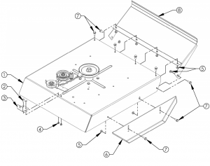
ASSEMBLY PARTS DETAIL
|
ITEM # |
DESCRIPTION |
PART # |
|
1 |
Guard – Engine, Cover |
19888* |
|
2 |
Guard – Engine, Right |
20595* |
|
3 |
Bolt – Serr Flange 5/16-18 X 3/4 |
NB596 |
|
4 |
Clip – Tinnerman 5/16-18 |
3706 |
|
5 |
Guard – Engine, Left |
19885* |
|
6 |
Guard – Engine, Front |
19884* |
|
7 |
Strap – Battery, 9″ |
AS013 |
|
8 |
Hook – Battery Strap |
AS049 |
|
9 |
Battery (Not Included) |
N/A |
|
10 |
Pad – Battery |
BATPAD |
|
11 |
Bolt – Serr Flange, 5/16-18 X 1 |
10548 |
|
12 |
Cover – Belt |
19889* |
|
13 |
Nut – Serr Flange 5/16-18 |
NB170 |
|
14 |
Channel – Side, Right |
19211* |
|
15 |
Channel – Side, Left |
19212* |
|
16 |
Clip – Nylon 1/2″ |
NB683 |
|
17 |
Bolt – Serr Flange, 5/16-18 X 2 1/4 |
NB622 |
|
18 |
Mount – Handle Height Adjust |
19214* |
|
19 |
Cover – Rear Frame |
21439* |
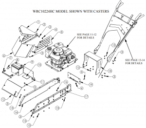
BATTERY NOT INCLUDED:REQUIRES A 12V LAWN AND GARDEN BATTERY WITH A 230 MIN CCA. U1 GROUP FOR CORRECT FIT.
When ordering replacement parts*USE PAINT CODE: TK=BLACK
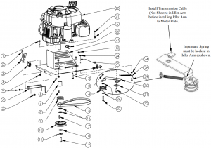
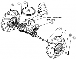
ENGINE & PULLEY ASSEMBLY
for models equipped with HONDA ENGINE
|
ITEM # |
DESCRIPTION |
PART # |
|
1 |
Nut – Nyloc 5/16-18 |
NB181 |
|
2 |
Bolt – Serr Flange, 5/16-18 X 1 |
10548 |
|
3 |
Nut – Serr Flange 5/16-18 |
NB170 |
|
4 |
Bolt – 5/16-24 X 1 HCF GR5 ZY |
NB451 |
|
5 |
Bolt – Serr Flange, 5/16-18 X 1 1/2 |
NB254 |
|
6 |
Spacer – Engine Pulley |
BB105S |
|
7 |
Weldment – Belt Retention |
10767 |
|
8 |
Belt – Transmission, 35″ |
690 |
|
9 |
Washer – 1 X 1 1/2 |
NB614HT |
|
10 |
Key Stock – 1/4 X 1 |
9031 |
|
11 |
Engine Pulley- 4.25″OD,1 1/4 ID |
BB105 |
|
12 |
Washer – .531IDX1 1/2OD |
TR150W |
|
13 |
Bolt – HCF, 7/16-20 X 1 1/2 |
NB637 |
|
14 |
Washer – Belleville 7/16 X 1 1/4 |
699 |
|
15 |
Pulley – Engine, 2.5″ |
2411 |
|
16 |
Key Stock – 1/4 X 1/2 |
4258 |
|
17 |
Bolt – 3/8-16 X 1 1/2 |
NB107 |
|
18 |
Washer – SAE Flat 3/8 |
NB272 |
|
19 |
Pulley – Idler, OD-2.16″, ID-3/8″ |
B27 |
|
20 |
Bolt – 3/8-16 X 1 |
NB604 |
|
21 |
Bushing – Idler |
6037 |
|
22 |
Transmission Idler Arm |
20594* |
|
23 |
Bolt – 1/4-20 X 3/4 |
NB250 |
|
24 |
Spring |
T2SM |
|
25 |
Nut – Serr Flange, 1/4-20 |
NB524 |
|
26 |
Nut – 2 Way Lock 3/8-16 |
NB280 |
|
27 |
Plate – Motor Base |
19213* |
|
28 |
Bolt – Serr Flange, 5/16-18 X 3/4 |
NB596 |
|
29 |
Valve – Oil Drain |
16000 |
|
30 |
Oil Drain Adaptor |
20881 |
|
31 |
Engine, Honda 389cc |
20694 |
|
N/A |
Wire Harness (NOT SHOWN) |
20988 |
|
N/A |
Cable – Transmission ( NOT SHOWN) |
20597 |
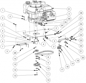
When ordering replacement parts*USE PAINT CODE: TK=BLACK
ENGINE & PULLEY ASSEMBLY
for models equipped with BRIGGS & STRATTON ENGINE
|
ITEM # |
DESCRIPTION |
PART # |
|
1 |
Bolt – 5/16-18 X 1 1/4 Serr. Flange |
NB253 |
|
2 |
Bolt – 5/16-18 X 3/4 Serr. Flange |
NB596 |
|
3 |
Bracket – ON/OFF Switch, Txt Blk |
19201* |
|
4 |
Switch – Toggle |
19192 |
| 5 | Nut – 5/16-18 Serr. Flange |
NB170 |
|
6 |
Belt Retention Weldment |
10767 |
|
7 |
Engine Pulley Spacer 1.75″ Long |
BB105S |
|
8 |
1/4 X 1/2 Key Stock |
4258 |
|
9 |
Engine Pulley- 2.5″ |
2411 |
|
10 |
Engine Pulley- 4.25″OD,1 1/4 ID |
BB105 |
|
11 |
Washer 7/16 X 1-1/4, Belleville |
699 |
|
12 |
Bolt – Serr Flange, 5/16-18 X 1 3/4 Gr5 |
NB515 |
|
13 |
Nut – 3/8-16 2 Way Locking |
NB280 |
|
14 |
Idler Pulley OD-2.16″, ID-3/8″ |
B27 |
|
15 |
Transmission Belt-35″ |
690 |
|
16 |
Washer – 1 X 1 1/2 |
NB614HT |
|
17 |
1/4 X 1 Key Stock |
9031 |
|
18 |
Washer – 1/2 X 1-1/2 |
TR150W |
|
19 |
Bolt – 7/16-20 X 1 1/2 Nyloc |
NB637 |
|
20 |
Engine- B&S 344 CC Power Built |
N/A |
|
21 |
Nut – 5/16-18 Nyloc Zy |
NB181 |
|
22 |
Valve – Oil Drain |
16000 |
|
23 |
Guard – Wire |
19478* |
|
24 |
1/4-20 Serr. Flange Nut |
NB524 |
|
25 |
Motor Plate |
19213* |
|
26 |
Washer – 3/8 SAE |
NB272 |
|
27 |
Bolt – 3/8-16 X 1 1/2 |
NB107 |
|
28 |
Spring |
T2SM |
|
29 |
Bolt – 1/4-20 X 3/4 |
NB250 |
|
30 |
Idler Arm |
10671* |
|
31 |
Idler Bushing |
6037 |
|
32 |
Bolt – 3/8-16 X 1 |
NB604 |
|
N/A |
Cable – Transmission ( NOT SHOWN) |
19209 |
|
N/A |
Wire Harness (NOT SHOWN) |
19202 |
When ordering replacement parts*USE PAINT CODE: TK=BLACK
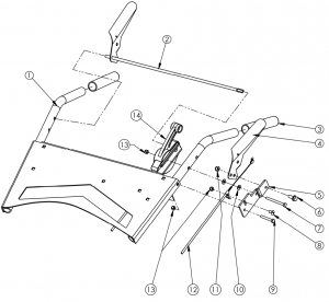
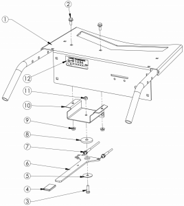
HANDLE BAR & LEVER ASSEMBLY
for Honda and Briggs models
|
ITEM # |
DESCRIPTION |
PART # |
|
1 |
Weldment – Handle Bar, Honda Models |
21437* |
|
1 |
Weldment – Handle Bar, Briggs Models |
21435* |
|
2 |
Lever – Blade Engage Weldment |
19444* |
|
3 |
Handle Grip |
7826 |
|
4 |
Ground Control Lever |
10685* |
|
5 |
Plate – Blade Lever |
10713* |
|
6 |
Bolt – 5/16-18 X 3/4 Flange Head |
NB596 |
|
7 |
Bolt – 1/4-20 X 2.75, YZ Gr 8 |
19455 |
|
8 |
Screw – 1/4-20 X 1/2 MSC ZP Truss Slot |
NB113 |
|
9 |
Bolt – 1/4-20 X 1.75 |
NB278 |
|
10 |
Washer – 1/4 SAE |
NB274 |
|
11 |
Nut – 5/16-18 Nyloc Zy |
NB181 |
|
12 |
Cable Assembly |
19209 |
|
13 |
Nut – 1/4-20 Nyloc |
NB180 |
|
14 |
Blade Engage Control |
19208 |
|
ITEM # |
DESCRIPTION |
PART # |
|
1 |
Weldment – Handle Bar, Honda Models |
21437* |
|
1 |
Weldment – Handle Bar, Briggs Models |
21435* |
|
2 |
Bolt – Serr Flange, 5/16-18 X 3/4 Gr 5 |
NB596 |
|
3 |
Bolt – 5/16-18 X 1 |
NB501 |
|
4 |
Handle Grip |
19911 |
|
5 |
Washer – .344 Id X 1.5 OD |
NB641 |
|
6 |
Shift Lever |
21443* |
|
7 |
Shift Cable |
21318 |
|
8 |
Idler Bushing |
6037 |
|
9 |
Nut – 5/16-18 Serr Flange |
NB170 |
|
10 |
Shift Lever Housing |
21442* |
|
11 |
Nut – 5/16-18 Nyloc |
NB181 |
|
12 |
Decal – Gear Selection |
21446 |
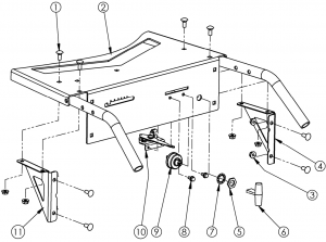
HANDLE BAR & ENGINE CONTROLS
for Honda models only
|
ITEM # |
PART # |
DESCRIPTION |
|
1 |
10216 |
Bolt – 5/16-18 X 3/4 Carriage, Gr5 |
|
2 |
21437 |
Weldment – Handlebar, 12v |
|
3 |
NB170 |
Nut – 5/16-18 Serr Flange |
|
4 |
21444 |
Gusset – WB Console, Right |
|
5 |
9087 |
Nut – Key Switch |
|
6 |
4226 KNOB |
Knob For P/N 3640 |
|
7 |
9088 |
Washer – Lock Key Switch |
|
8 |
NB114 |
Bolt – Tcs 1/4-20 X 1/2 Unslot Zy Gr2 |
|
9 |
3623 |
Key Switch |
|
10 |
4226 |
Cable – Throttle |
|
11 |
21445 |
Gusset – WB Console, Left |
|
NOT SHOWN |
||
|
KSK |
Keys – Set of Two |
|
|
20988 |
Wiring Harness |
TRANSAXLE ASSEMBLY
|
ITEM # |
DESCRIPTION |
PART # |
|
1 |
Wheel – Asy Right; WB24 4.8×8 |
2401RK |
|
2 |
Screw – Set 5/16-18 X 1/2 |
NB312 |
|
3 |
Pulley – Transmission, 8″ |
2410 |
|
4 |
Bolt – Hex 1/4-28 X 3/4 GR8 |
06X105 |
|
5 |
Washer – 1/4 Split Lock, |
NB135 |
|
6 |
Washer – SAE Flat 1/4 ZY |
NB274 |
|
7 |
Retainer – Cable Mount |
21441* |
|
8 |
Mount – Shift Cable |
21440* |
|
9 |
Transaxle – 4 Speed |
19563 |
| 10 | Key Stock – 3/16 X 1 1/2 |
2434 |
|
11 |
Wheel – Asy Left; WB24 4.8×8 |
2401LK |
|
12 |
Washer – 3/4ID X 1 1/4OD |
NB184 |
|
13 |
Ring – E-Style Retaining 3/4 |
NB621 |
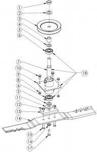
BLADE DRIVER ASSEMBLY
|
ITEM # |
DESCRIPTION |
PART # |
|
1 |
Nut – Jam 3/4-16 |
NB175 |
|
2 |
Washer – Belleville .760 X 1.5 X .098 |
AS155 |
|
3 |
Pulley – Blade, 5.5″ |
20651 |
|
4 |
Spacer – 3/4 ID X 1 |
12823 |
|
5 |
Washer – 3/4 ID X 1 1/4 OD |
NB179 |
|
6 |
Bearing – Blade |
B98 |
|
7 |
Shaft – Blade 6″, Long Shoulder |
9078 |
|
8 |
Nut – Serr Flange 5/16-18 |
NB170 |
|
9 |
Housing – Blade Bearing |
9091* |
|
10 |
Bolt – Serr Flange, 5/16-18 X 3/4 |
NB596 |
|
11 |
Washer – Flat 3/4 ID X 1 3/4 OD |
B98W |
|
12 |
Nut – Lock, Two Way 3/8-24 |
NB216 |
|
13 |
Plate – Blade Mount |
9008 |
|
14 |
Blade – 24″ (B&S) | 9016 |
| Blade – G6 Gator 24″ (Honda) |
20114 |
|
|
15 |
Bolt – 3/8-24 X 1 HCC GR5 ZY (B&S) | NB238 |
| Bolt – 3/8-24 X 1 1/4 HCC GR5 ZY (Honda) |
NB166 |
|
|
16 |
Washer – SP Bellville .413 X.945 X.118 |
NB607 |
|
17 |
Bolt – HHC 3/8-24 X 1 |
NB238N |
|
18 |
Blade Driver – Assembly |
10712 |
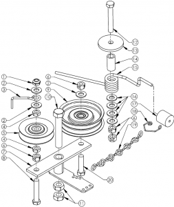
BRAKE ASSEMBLY
|
ITEM # |
DESCRIPTION |
PART # |
|
1 |
Nut – Jam, Nyloc 3/8-16 |
NB207 |
|
2 |
Washer – SAE Flat 3/8 |
NB272 |
|
3 |
Finger for Belt Release |
T30F |
|
4 |
Nut – Jam 3/8-16 |
NB174 |
|
5 |
Pulley – Idler Clutch, 2 3/4 OD |
T30V |
|
6 |
Nut – 2 Way Lock 3/8-16 |
NB280 |
|
7 |
Idler – Blade Weldment |
10668* |
|
8 |
Bolt – HTC, 3/8-16 X 2 |
NB231 |
|
9 |
Pulley – Idler, OD3.25 X ID3/8 |
B527 |
|
10 |
Bolt – 1/2-13 X 3 HCC |
NB131 |
|
11 |
Nut – Jam Lock, 1/2-13 2-Way |
NB121 |
|
12 |
Bolt – 3/8-16 X 2 1/2 HTC |
NB619 |
|
13 |
Washer – Idler, ZP |
6040Z |
|
14 |
Spacer – .625 OD X 1.25 |
8072* |
|
15 |
Spring – Torsion Brake |
BT297 |
|
16 |
Washer – Hardened 3/8 |
NB196 |
|
17 |
Pad – Brake, Cylindrical |
9114 |
|
18 |
Spring – Brake Pad Retainer |
BP370S |
|
19 |
Chain – Sgl Jk Chn, Zps, Sz12, 16# |
AS080 |
|
20 |
Bolt – 3/8-16 X 1 1/2 HCC |
NB107 |
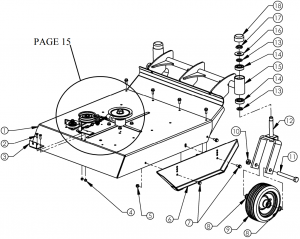
DECK & CASTER ASSEMBLY (IF EQUIPPED)
|
ITEM # |
DESCRIPTION |
PART # |
|
1 |
Deck – Weldment |
10695* |
|
2 |
Bolt – 1/4-20 X 3/4 |
NB250 |
|
3 |
Clip – Blade Engagement Cable |
10673* |
|
4 |
Nut – Nyloc 1/4-20 |
NB180 |
|
5 |
Nut – Serr Flange 5/16-18 |
NB170 |
|
6 |
Weldment – WB Skid |
18512* |
|
7 |
Bolt – Serr Flange, 5/16-18 X 3/4 |
NB596 |
|
8 |
Washer – 5/8 ID X 1 OD |
NB149 |
|
9 |
Tire/Wheel – 8 X 3 Flat Free |
21284 |
|
10 |
Nut – Lock Jam, 5/8-11 2 Way |
NB595 |
|
11 |
Bolt – 5/8-11 X 5 |
19642 |
|
12 |
Weldment – Caster |
19638* |
|
13 |
Washer – 13/16 X 1 1/4 X 1/8 |
NB195 |
|
14 |
Bearing |
B98 |
|
15 |
Weldment – Brush Guard Housing |
19631* |
|
16 |
Washer – Flat |
17X195 |
|
17 |
Nut – Jam, Nyloc 3/4-16 |
NB122 |
|
18 |
Cap |
094618 |
DECK & FRONT GUARD ASSEMBLY (IF EQUIPPED)
|
ITEM # |
DESCRIPTION |
PART # |
|
1 |
Deck – Weldment |
10695* |
|
2 |
Bolt – 1/4-20 X 3/4 |
NB250 |
|
3 |
Clip – Blade Engagement Cable |
10673* |
|
4 |
Nut – Nyloc 1/4-20 |
NB180 |
|
5 |
Nut – Serr Flange 5/16-18 |
NB170 |
|
6 |
Weldment – WB Skid |
18512* |
|
7 |
Bolt – Serr Flange, 5/16-18 X 3/4 |
NB596 |
|
8 |
Guard – Predator Brush |
10681* |
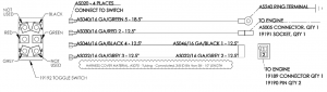
WIRING CONFIGURATION HONDA
Engine Models Wiring Harness PN 20988
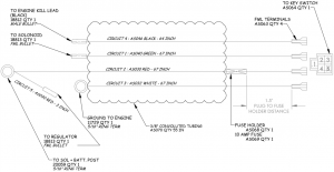
WIRING CONFIGURATION
Briggs Engine Models Wiring Harness PN 19202
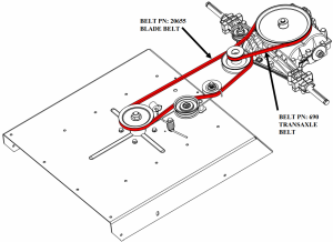
BELT ROUTING
|
Model Number |
||||
|
Specifications |
WRC10224HC | WRC10224H | WRC11524BSC |
WRC11524BS |
|
Engine |
Honda GXV390 | Honda GXV390 | Brigs & Stratton PowerBuilt |
Brigs & Stratton PowerBuilt |
|
Displacement |
389 CC | 389 CC | 344 CC |
344 CC |
|
Fuel Type |
*Unleaded 86 Octane | *Unleaded 86 Octane | *Unleaded 87 Octane |
*Unleaded 87 Octane |
|
Fuel Capacity |
2.2 US Qts | 2.2 US Qts | 2.8 US Qts |
2.8 US Qts |
|
Oil Type |
*SAE 10W-30 | *SAE 10W-30 | *SAE 10W-30 |
*SAE 10W-30 |
|
Oil Capacity |
1.2 US Qts | 1.2 US Qts | 1.5 US Qts |
1.5 US Qts |
|
Front Tire Size |
8 X 3 Flat Free | N/A | 8 X 3 Flat Free |
N/A |
|
Rear Tire Size |
16″ Dia. X 4″ Chevron | !6″ Dia. X 4″ Chevron | !6″ Dia. X 4″ Chevron |
!6″ Dia. X 4″ Chevron |
|
Rear Tire Pressure |
17 PSI Max | 17 PSI Max | 17 PSI Max |
17 PSI Max |
|
Overall Length |
93.5″ | 87″ | 93.5″ |
87″ |
|
Overall Height |
38.7 “to 41.7” | 38.7 “to 41.7” | 38.7 “to 41.7” |
38.7 “to 41.7” |
|
Unit Weight |
291 Lbs | 256 Lbs | 281 Lbs |
246 Lbs |
LIMITED WARRANTY
The manufacturer’s warranty to the original consumer purchaser is: This product is free from defects in materials and workmanship for a period of (1) year from the date of purchase by the original consumer purchaser. We will repair or replace, at our discretion, parts found to be defective due to materials or workmanship. This warranty is subject to the following limitations and exclusions:
- Engine Warranty• All engines utilized on our products have a separate residential or commercialwarranty extended to them by the individual engine manufacturer. Any engine service is the responsibility of the engine manufacturer and in no way is Swisher or its agents responsible for the engine warranty. Please visit engines.honda.com and click on find a dealer or find a distributor. The Briggs & Stratton Engine Service Hot Line is 1-800-233-3723.
- Limitation• This warranty applies only to products which have been properly assembled,adjusted, and operated in accordance with the instructions contained within this manual. This warranty does not apply to any product of Swisher that has been subject to alteration, misuse, abuse, improper assembly or installation, shipping damage, or to normal wear of product.
- Commercial Use• Only Commercial Pro branded Walk Behind Rough Cut Trail Cutters are warranted for commercial use for a period of (1) year from the date of purchase. Non Commercial Pro Products are not intended for commercial use and carry no commercial use warranty.
- Exclusions• Excluded from this warranty are normal wear, normal adjustments, and normal maintenance.
In the event you have a claim under this warranty, you must return the product to an authorized service dealer. All transportation charges, damage, or loss incurred during transportation of parts submitted for replacement or repair under this warranty shall be borne by the purchaser. Should you have any questions concerning this warranty, please contact us toll-free at 1 800-222-8183. The model number, serial number, date of purchase, and the name of the authorized Swisher dealer from whom you purchased the mower will be needed before any warranty claim can be processed.THIS WARRANTY DOES NOT APPLY TO ANY INCIDENTAL OR CONSEQUENTIAL DAMAGES AND ANY IMPLIED WARRANTIES ARE LIMITED TO THE SAME TIME PERIODS STATED HEREIN FOR ALL EXPRESSED WARRANTIES. Some states do not allow the limitation of consequential damages or limitations on how long an implied warranty may last, so the above limitations or exclusions may not apply to you. This warranty gives you specific legal rights and you may have other rights, which vary from state-to-state. This is a limited warranty as defined by the Magnuson-Moss Act of 1975.
RESIDENTIAL & COMMERCIAL PRO 24” WALK BEHIND ROUGH CUT TRAIL CUTTERS
Each cutter has its own model number. Each engine has its own model number. The model number for the cutter will be found on the right hand side of the drive belt housing. The model number for the engine will be found on the engine block. All cutter parts listed herein may be ordered directly from Swisher or your nearest Swisher dealer.All engine parts may be ordered from the nearest dealer of the engine supplied with your cutter
WHEN ORDERING PARTS, PLEASE HAVE THEFOLLOWING INFORMATION AVAILABLE:
* PRODUCT – WALK BEHIND ROUGH CUT* SERIAL NUMBER – _______________* MODEL NUMBER – _______________* ENGINE MODEL NUMBER – _______________TYPE – _______________* PART NUMBER* PART DESCRIPTION
TELEPHONE – 1-800-222-8183 FAX – 1-660-747-8650
SWISHER ACQUISITION INC.1602 CORPORATE DRIVE WARRENSBURG, MO 64093

References
[xyz-ips snippet=”download-snippet”]