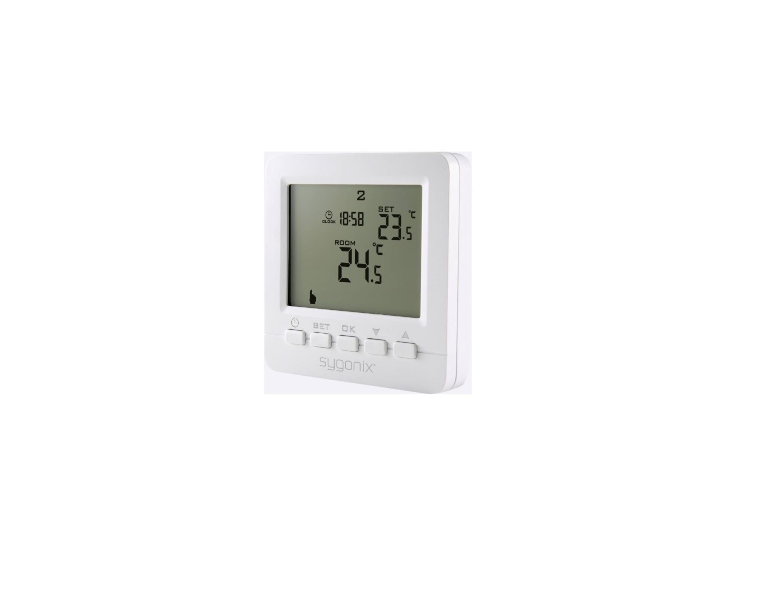
sygonix 2250409 Heating Thermostat with Sensor
Intended use
The heating thermostat is intended for temperature control in conjunction with an electric heater. The product operates under the mains voltage; a mains operated load can be connected and switched on or off by temperature control.It is equipped with an internal and external sensor (probe). The external sensor can be used to measure the temperature in a different location to the thermostat, such as on the floor with an electric floor heating system.A keypad lock can be activated to protect against incorrect operation, and a backup (nonremovable) capacitor supplied with the unit serves to preserve data in case of power failure. This device has an IP20 ingress protection rating and is suitable for dry rooms and indoor use. Do not use it outdoors. Contact with moisture, e.g. in bathrooms, must be avoided under all circumstances.For safety and approval purposes, you must not rebuild and/or modify this product. If you use the product for purposes other than those described above, the product may be damaged. In addition, improper use can result in short circuits, fires, electric shocks or other hazards. Read the instructions carefully and store them in a safe place. Make this product available to third parties only together with its operating instructions.This product complies with the statutory national and European requirements. All company names and product names are trademarks of their respective owners. All rights reserved.
Delivery content
- Thermostat
- 2x mounting screws
- External sensor
- Operating instructions
Up-to-date operating instructions
Download the latest operating instructions at www.conrad.com/downloads or scan the QR code shown. Follow the instructions on the website.
Explanation of symbols
 |
The symbol with the lightning in the triangle is used if there is a risk to your health, e.g. due to an electric shock |
 |
The symbol with the exclamation mark in the triangle is used to indicate important information in these operating instructions. Always read this information carefully. |
| The arrow symbol indicates special information and advice on operation. | |
 |
The product is only intended to be installed and used in dry indoor rooms; it must not get damp or wet. |
 |
The product is designed according to protection Class II (reinforced or double insulation, protective insulation). |
 |
Observe the operating instructions! |
Safety instructions
Read the operating instructions carefully and especially observe the safety information. If you do not follow the safety instructions and information on proper handling in this manual, we assume no liability for any resulting personal injury or damage to property. Such cases will invalidate the warranty/guarantee.
a) General information
- The device is not a toy. Keep it out of the reach of children and pets.
- Do not leave packaging material lying around carelessly. This may become dangerous playing material for children.
- Protect the appliance from extreme temperatures, direct sunlight, strong jolts, high humidity, moisture, flammable gases, steam and solvents.
- Do not place the product under any mechanical stress.
- If it is no longer possible to operate the product safely, take it outof operation and protect it from any accidental use. Safe operation can no longer be guaranteed if the product:– is visibly damaged,– is no longer working properly,– has been stored for extended periods in poor ambient conditions or – has been subjected to any serious transport-related stresses.
- Please handle the product carefully. Jolts, impacts or a fall even from a low height can damage the product.
- Consult an expert when in doubt about the operation, safety or connection of the appliance.
- If you have questions which remain unanswered by these operating instructions, contact our technical support service or other technical personnel.
b) Installation / connection Caution, safety hazard!The product should only be installed by people with relevant electrical knowledge and experience! *)
If it is not installed properly, you risk:
- your own life
- the life of user of the electrical device
If it is not installed properly, you risk severe damage to property, e.g. by fire.
You face the risk of personal liability for personal injury and material damage.
Always consult an electrician!
*) Technical knowledge required to perform the installation:For the installation, the following specialist knowledge is required in particular:
- The “Five safety rules”: Disconnect from the mains; protect against accidental switch-on; ensure there is no voltage; earth and short-circuit; cover or protect adjacent live parts
- Use of suitable tools, measuring devices and personal protective equipment, where necessary
- Analysis of measurement results
- Use of electrical installation materials to meet the requirements for disconnection
- IP protection ratings
- Installation of electrical installation materials
- Type of power supply (TN system, IT system, TT system) and the corresponding connection criteria (classic earthing, protective earthing, necessary additional measures etc.)If you are not a professional, do not do it yourself, have it performed by a specialist.
Further warnings:
- The construction of the product corresponds to the protection-class II (double or reinforced isolation). Ensure that the insulation of the housing is neither damaged nor destroyed.
- During installation, all poles must be disconnected from the mains voltage, e.g., via RCD. There must be an appropriately rated fuse or circuit breaker between the RCD and the product.
- The device must be voltage-free during installation and connection. Furthermore, turn off the automatic circuit breaker and the earth leakage circuit breaker to disconnect all the poles from the mains voltage.Secure it against unauthorised reconnection, e.g., with a warning sign. Check to make sure there is no voltage with a suitable measuring instrument (e.g., a digital multimeter).
- Never connect the product to the power supply immediately after it has been transferred from a cold room into a warm one (e.g., during transport). The condensation that forms might destroy the device. Moreover, there is danger of electric shock!
- Allow the product to reach room temperature. Wait until the condensation has evaporated. This might take several hours. Only after this, should it be installed, connected to the mains supply and put into use.
- Do not use the product in rooms with adverse environmental conditions, where combustible gases, vapours or dust are or may be present! There is a danger of explosion!
c) Ingress protection
- This device has an IP20 ingress protection rating and is suitable for dry rooms.
- There is protection against touching live components and ingress from foreign particles >12.5 mm.
- There is no protection against water, combustible gases, and vapours.
Installation
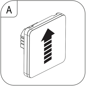
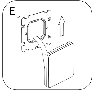
- To remove the front panel, slide the front part with the display upwards (A). The two parts are connected by a ribbon cable (B).
 The ribbon cable can be disconnected if needed. Be careful not to damage it.
 - On the back of the wall thermostat (C) there are 6 terminals for connecting the:– The main power supply– Electrical load– External NTC temperature sensor● Connect the mains power supply to the corresponding inputs 3 and 4.● Connect the load (e.g., an electric radiator or electric floor heating) to corresponding outputs 1 and 2.
If the load requires a protective earth connection it must be connected separately. The thermostat complies with protection class II and does not by itself require a protective earth connection - If using an external temperature sensor (probe), it should be connected to terminals 5 and 6 (C). There is no polarity so it does not matter which way you connect the wires.
When laying out the connection cable, make sure it is protected from sharp edges. Never fasten the connection cable with nails, screws or similar. - Insert the wall thermostat into the flush-mounted/ surface-mounted box and fasten it using the included screws (D).
Make sure that the cables are not damaged when inserting the wall thermostat into the flush-mounted/surface-mounted box - Reconnect the ribbon cable if needed. It can only be connected on way, do not use force when plugging in!
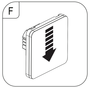
- Align the front panel (E) and push it down (F). It should lock into place.
- Switch on the voltage supply.
- The wall thermostat is now operational.

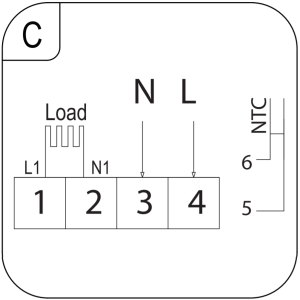 – The main power supply– Electrical load– External NTC temperature sensor● Connect the mains power supply to the corresponding inputs 3 and 4.● Connect the load (e.g., an electric radiator or electric floor heating) to corresponding outputs 1 and 2.
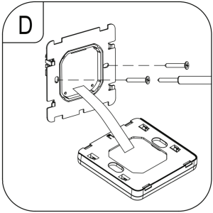
Operating elements
a) Display

- Six period program
- External sensor active
- Automatic mode
- Manual mode
- Holiday mode
- Time
- Weekday (1 = Monday, 7 = Sunday)
- Target temperature setting
- Open window (activated)
- Measured temperature (internal or external probe)
- Keypad lock
- Heating
b) Icons
| Icon | Description | Icon | Description |
 |
Visible when the keypad is locked. Disappears when keypad is unlocked. |  |
Auto mode: Weekly schedule program is running. |
|
Visible when heating is ON. Disappears when heating is OFF. |  |
Manual mode. |
 |
The open window icon shows if it has been activated. |  |
Auto mode temporary manual override. |
 |
External NTC sensor (probe) temperature shown.Advanced setting “N2” should be set:“Advanced settings” → “BN” → “N2”. |  |
Holiday mode: Set the number of days you will be away and a temperature. |
c) Button functions
| Button | Function |
 |
Power ON / OFF. |
 |
|
 |
|
 |
|
 |
|
Operation
a) Power ON/OFF
- Press the button to switch the wall thermostat ON or OFF.
- When the thermostat is switched off, the display goes out and no temperature control takes place.
b) Set time and weekday
![]() The wall thermostat must first be on and in normal operating mode (exit “System settings”). Settings will exit and be saved if no keys are pressed for approx. 10 seconds.
The wall thermostat must first be on and in normal operating mode (exit “System settings”). Settings will exit and be saved if no keys are pressed for approx. 10 seconds.
- Press and the minutes will flash.– Press or to adjust values.– Press to save the setting.
- Adjust the hours:– Press or to adjust values.– Press to save the setting.
- Adjust the day of week (1 = Monday… 7 = Sunday).– Press or to adjust values.– Press to save the setting.
- Settings will be saved and the thermostat will returns to normal operation.
c) Switch between automatic and manual mode
![]() The wall thermostat must first be on and in normal operating mode (exit “System settings”).
The wall thermostat must first be on and in normal operating mode (exit “System settings”).
- Press to switch between automatic and manual mode .– Automatic mode: The temperature settings will be based the active program preset.– Manual mode: The temperature can be set manually using the or buttons.
d) Manual override automatic mode
The wall thermostat must first be on and in normal operating mode (exit “System settings”).
- If a different temperature is temporarily needed during automatic mode, you can set it using the or buttons. Both the and symbols will show on the display.
- The manual override remains active until the automatic mode setting reaches the next time interval. When that happens:– The manual override will be disabled the thermostat will return to automatic mode.– The symbol will disappear.
e) Keypad lock
- Press and hold for approx. 5 seconds to turn the parental control lock ON / OFF.
- The lock symbol will show to indicate that the parental lock is ON. Depending on the “System settings” → “General” → “A3”, two different parental control locks are possible:0 = All buttons except the power button will be locked.1 = All buttons will be locked.
Holiday mode
![]() The wall thermostat must first be on and in normal operating mode (exit “System settings”). Use holiday mode to set a time and temperature for the days you will be away.
The wall thermostat must first be on and in normal operating mode (exit “System settings”). Use holiday mode to set a time and temperature for the days you will be away.
Activate
- Press and hold for approx. 3 – 5 seconds until the symbol shows on the display.
- Turn holiday mode “on”.– Press or to adjust values.– Press to save the setting.
- Set the number of days you will be away “1 – 30”.– Press or to adjust values.– Press to save the setting.
- Set the temperature.– Press or to adjust values.– Press to save the setting.
- The symbol shows on the display to indicate that holiday mode is active.
Exit holiday modePress ![]() to exit holiday mode and return to manual or auto mode
to exit holiday mode and return to manual or auto mode
Weekly schedule program
a) Overview6 time periodsYou can configure temperature settings for 6 time periods throughout the day. An icon will indicate which time period is active.![]() Default times and temperatures for each period are shown below:
Default times and temperatures for each period are shown below:
 |
 |
 |
 |
 |
 |
|
1: Wake up |
2: Outdoor | 3: Home | 4: Outdoor | 5: Home |
6: Sleep |
|
06:00 |
08:00 | 11:30 | 13:30 | 17:00 | 22:00 |
| 20 °C | 15 °C | 15 °C | 15 °C | 15 °C |
15 °C |
Weekday intervals
![]() Weekday intervals are based on the selected program. Refer to section “System settings” → “General” → “A6″.
Weekday intervals are based on the selected program. Refer to section “System settings” → “General” → “A6″.
| Program | Icon | Weekday interval |
| 0 |  |
5 days same / 2 days same |
| 1 |  |
6 days same / 1 day same |
| 2 |  |
7 days same |
b) Program a weekly schedule
General setting
- Press to turn the power OFF.
- Press and hold for approx. 3 – 5 secs to enter settings mode.
- Press SET to toggle to setting “A6”.
- Press / to select a program (0, 1, 2).
- Press to exit settings mode. Settings will also be saved if no buttons are pressed for approx. 10 sec.
Program a schedule
- Press power to turn the power ON.
- If the backlight is off, press to turn it on, then press and hold for approx. 3 – 5 secs to enter settings mode. The first period icon “1: Wake up” will show, and the time will flash.
- Set the time (hours: minutes)– Press or to adjust values.– Press to save and set the next value.
- Set the temperature– Press or to adjust values.– Press to save and set the next period The next period icon “2: Outdoor” will show, and the time will flash.
- Repeat steps 3 and 4 to set all 6 periods for the day.
- Settings will be saved if no buttons are pressed for approx. 10 sec.
c) Switch programmed schedule ON/OFF
- Press to switch the programmed schedule ON or OFF.
- The icon appears when the programmed schedule is ON.
System settings and defaults
Adjusting system settings may cause your thermostat to behave unexpectedly. Read the instructions carefully before adjusting any settings. Refer to section “Troubleshooting” for furtherinformation.a) General
- Press to turn the power OFF.
- Press and hold for approx. 3 – 5 secs to enter general settings mode.– Press to toggle through settings “A1” to “AE”.– Press / to adjust values.
- Press to exit settings mode. Settings will also be saved if no buttons are pressed for approx. 10 sec.
| Description | Settings / defaults | |
| A1 | Temperature offset | Setting range: -9 to +9 °C; Default: Measured temperature ±0.5 °C |
| A2 | Switching differential (hysteresis) | Setting range: 0.5 to 2.5 °C; Default: 1 °CExample: For a setting of 1 °C and the thermostat temperature set to 20 °C, the thermostat will switch heating on at 19 °C and off at 21 °C. |
| A3 | Keypad lock | Settings:0 = All buttons except the power |
| A4 | Behaviour after power failure | Settings:0 = Return to previous function; 1 = Power OFF; 2 = Power ON Default: 0 |
| A5 | Backlight time | Settings: 5 to 30 secs; Default: 10 secs |
| A6 | Weekly program settings | The correct weekday must be set for the program to coincide with the weekend. See section “Operation” → “Set time and weekday”.
|
| A7 | Min. temperature. | Set the lowest selectable temperature.Setting range: 1 to 10 °C; Default: 5 °C |
| A8 | Max. temperature | Set the max. selectable temperature.Setting range: 20 to 70 °C; Default: 35 °C |
| A9 | Low temperature protection | Frost protection: The output is activated if the temperature measured by the sensor falls below the value set here.
|
| AA | High temperature protection (external sensor only) | It is to prevent the floor temperature from getting too high, for example. If the window is open and the room temperature cannot heat up but the floor heating is working and increasing to compensate.
Example: If set to 50 °C and the external (floor) sensor detects 50 °C, the thermostat will switch the output off. |
| AB | High temperature protection / difference setting (external sensor) | Setting range: 1 to 9 °C; Default: 2 °CExample: “AA” limit set to 45°C, and “AB” is set to 2 °C. If the temperature rises to 45°C the output is switched off. If the temperature drops to 43°C the output is switched on. This only works if the indoor temperature is lower than set temperature. |
| AC | Ventilation mode (open window) | If this setting is active, the thermostat will detect if a window is open and switch the output (heater) off.
|
| AD | Ventilation mode working time | Setting range: 10 – 20 minutes; Default: 10 mins |
| AE | Reset all settings to defaults | Press and hold OK for approx. 3 – 5 secs until all segments show on the display. The power will turn off when all settings have been reset. |
b) Advanced
- Press to turn the power OFF.
- Press and hold for approx. 3 – 5 secs to enter advanced settings mode.– Press to toggle through settings “BN” → “BC” → “BO”.– Press / to adjust values.
- Settings will be saved if no buttons are pressed for approx. 10 sec
| Description | Settings / defaults | |
| BN | Sensor selection | Settings:
|
| BC | Descaling | Settings: 0 = closed, 1 = open; Default: 0 (closed) |
| BO | Program data | Cannot be changed. |
Error Codes
An error code will show if there is a problem with the internal or external sensor. When this happens the thermostat will stop heating until the cause of the error is removed.
| Code | Description | Suggestion |
| E1 | Internal sensor error |
|
| E2 | External sensor error |
|
Care and cleaning
- The product is maintenance free.
- Use a dry, soft, lint-free cloth to wipe the panel. Do not use aggressive cleaning agents, as these can cause discoloration.
![]() Activate the keypad lock when wiping the front panel. Accidentally pressing the sensor keys can cause unintended settings.
Activate the keypad lock when wiping the front panel. Accidentally pressing the sensor keys can cause unintended settings.
Disposal
![]() Electronic devices are recyclable waste and must not be disposed of in the household waste. At the end of its service life, dispose of the product in accordance with applicable regulatory guidelines.You thus fulfill your statutory obligations and contribute to the protection of the environment.
Electronic devices are recyclable waste and must not be disposed of in the household waste. At the end of its service life, dispose of the product in accordance with applicable regulatory guidelines.You thus fulfill your statutory obligations and contribute to the protection of the environment.
Technical data
a) General
Input voltage / current ………………. 90 – 240 V/AC, 50/60 HzMax. switching power ………………. 3000 W (resistive load)2000 W (inductive load)Contact load capacity ………………. 16 A, 250 VMemory backup ………………………. Stored on non-removable capacitorTime: approx. 7 daysSettings: < 10 yearsSurface mounting ……………………. Back box sizes: 60 mm, 80 mmDisplay accuracy …………………….. 0.5 ºCSensor …………………………………… 1x internal, 1x external (probe)External sensor (probe) ……………. NTC (10 k) 1 %Ingress protection ……………………. IP20Display size (W x H) ………………… 63.8 x 51.6 mmOperating/Storage conditions ……. 1 to 70 ºC, <85 % RH (non-condensing)Probe wire length …………………….. 2.5 mDimensions (W x H x D) …………… 86 x 86 x 40 mmWeight …………………………………… 170 g
| This is a publication by Conrad Electronic SE, Klaus-Conrad-Str. 1, D-92240 Hirschau (www.conrad.com). All rights including translation reserved. Reproduction by any method, e.g. photocopy, microfilming, or the capture in electronic data processing systems require the prior written approval by the editor. Reprinting, also in part, is prohibited. This publication represent the technical status at the time of printing.
Copyright 2020 by Conrad Electronic SE. *2250409_v4_1020_02_dh_m_en |
 report this ad
References
[xyz-ips snippet=”download-snippet”]