Tag: teltonika
-

TELTONIKA FMB122 Dual-Sim Tracker with External GNSS Antenna User Manual
FMB122Dual-SIM tracker withexternal GNSS antennaQuick Manual v1.6 Know your device Pinout Table 1 FMB122 2×6 socket pinout PIN NUMBER PIN NAME DESCRIPTION 1 VCC (10-30) V DC (+) Power supply (+10-30 V DC). 2 AIN 1 Analog input, channel 1. Input range: 0-30 V DC. 3 AIN 2 / DIN 3 0-30 V DC /…
-
TELTONIKA GPRS/GNSS tracker with Bluetooth FMB120 User Manual
TELTONIKA GPRS/GNSS tracker with Bluetooth FMB120 User Manual Know your device Pinout Table 1 FMB120 2×6 socket pinout PIN NUMBER PIN NAME DESCRIPTION 1 VCC (10-30) V DC (+) Power supply (+10-30 V DC). 2 AIN 1 Analog input, channel 1. Input range: 0-30 V DC. 3 AIN 2 / DIN 3 Analog input, channel…
-
TELTONIKA RUT850 Router User Guide
TELTONIKA RUT850 Router https://wiki.teltonika-networks.com/ FRONT VIEW BACK VIEW POWER SOCKET PINOUT HARDWARE INSTALLATION Push the SIM holder button with the SIM needle. Pull out the SIM holder. Insert your SIM card into the SIM holder. Slide the SIM holder back into the router. Attach all antennas. Connect the power adapter to the socket on the…
-
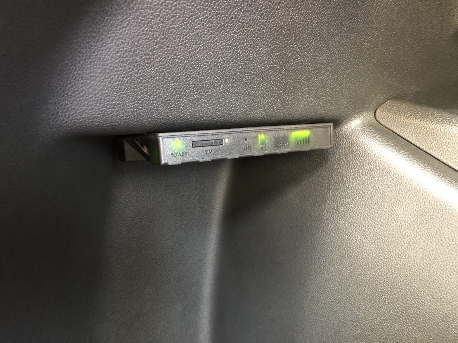
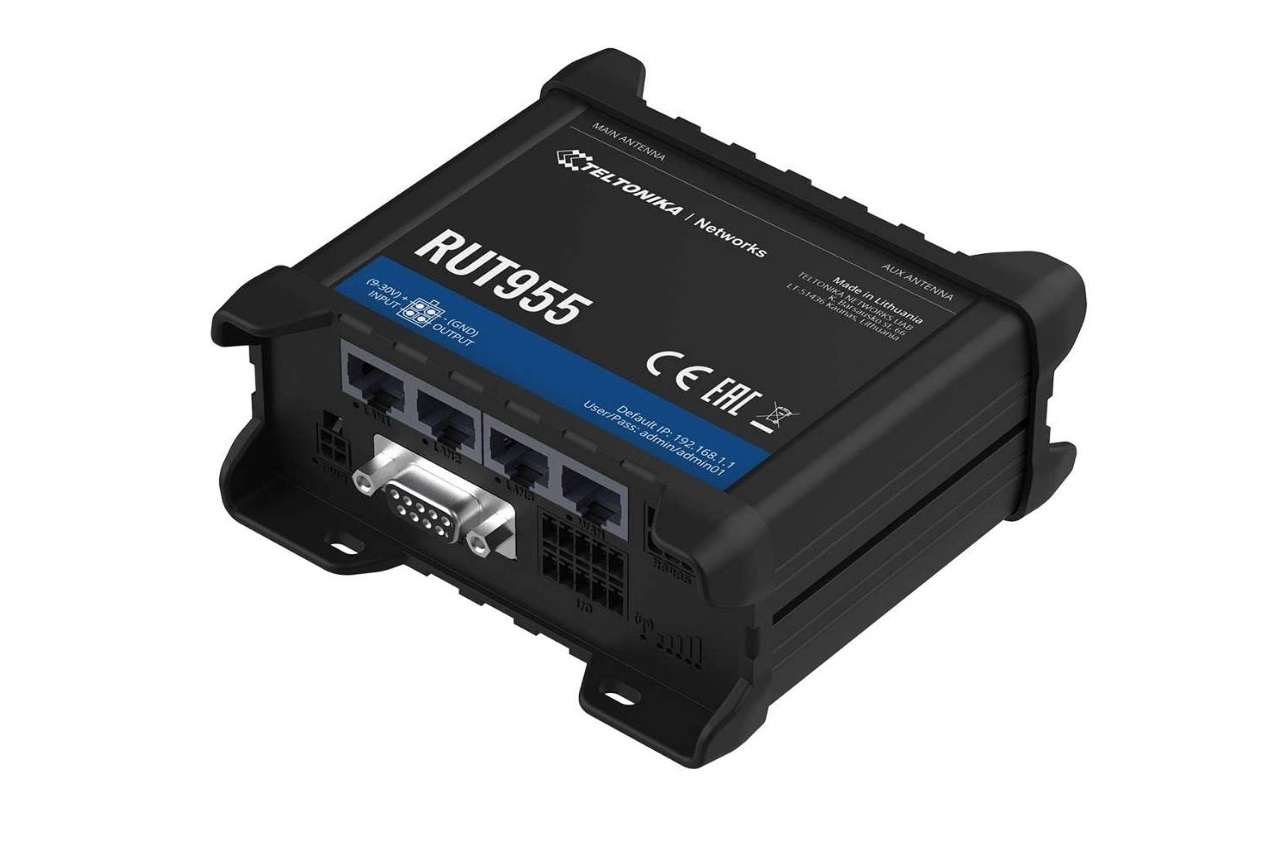
TELTONIKA RUT955 LTE Router User Guide
TELTONIKA RUT955 LTE Router User Guide Product Overview FRONT VIEW BACK VIEW POWER SOCKET PINOUT HARDWARE INSTALLATION Push the SIM holder button with the SIM needle. Pull out the SIM holder. Insert your SIM card into the SIM holder. Slide the SIM holder back into the router. Attach all antennas. Connect the power adapter to…
-
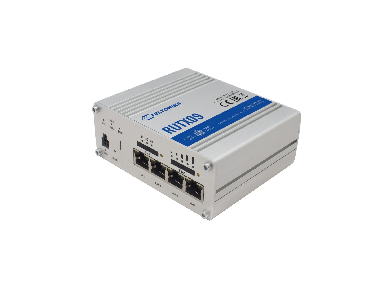
TELTONIKA RUTX09 – LTE-A CAT6 Dual-SIM Router User Guide
TELTONIKA RUTX09 – LTE-A CAT6 Dual-SIM Router User Guide OVERVIEW FRONT VIEW BACK VIEW POWER SOCKET PINOUT HARDWARE INSTALLATION Pull out the SIM needle from the front panel of the router. Push the SIM holder button with the SIM needle. Pull out the SIM holder. Insert your SIM card into the SIM holder. Slide the…
-
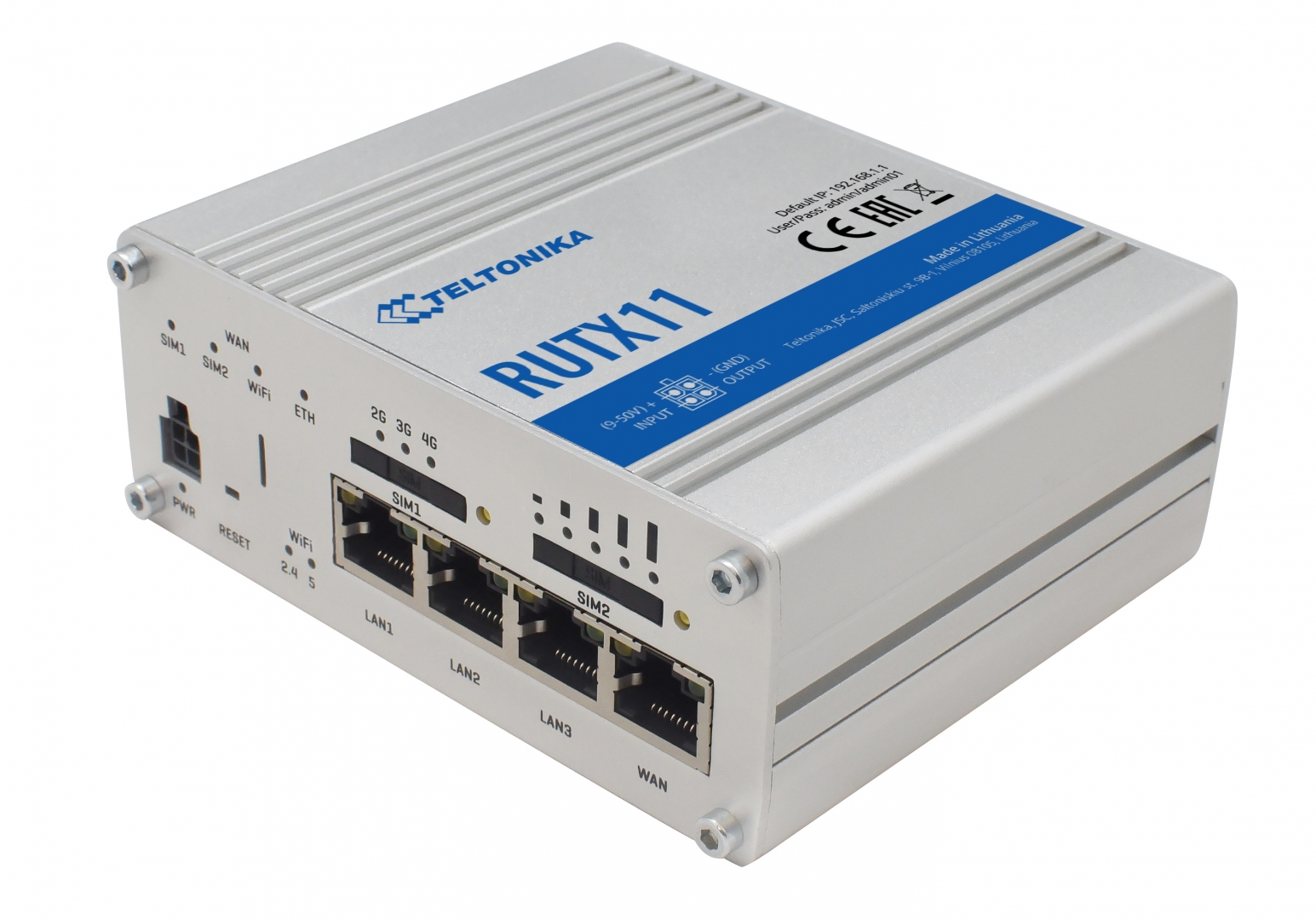
TELTONIKA RUTX11 – Dual-SIM Gigabit Router User Guide
TELTONIKA RUTX11 – Dual-SIM Gigabit Router User Guide RUTX11 Wiki knowledge base https://wiki.teltonika-networks.com/ FRONT VIEW BACK VIEW POWER SOCKET PIN OUT HARDWARE INSTALLATION Pull out the SIM needle from the front panel of the router. Push the SIM holder button with the SIM needle. Pull out the SIM holder. Insert your…
-
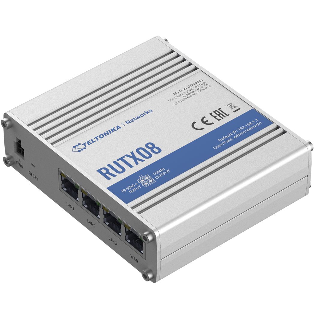
TELTONIKA RUTX08 Gigabit Ethernet Router User Guide
TELTONIKA RUTX08 Gigabit Ethernet Router User Guide RUTX08 Wiki knowledge base https://wiki.teltonika-networks.com/ FRONT VIEW BACK VIEW POWER SOCKET PIN OUT HARDWARE INSTALLATION Connect the power adapter to the socket on the front of the device. Then plug the other end of the power adapter into a power outlet. Connect to the…
-
TELTONIKA TRB141 Small Industrial LTE Cat 1 Gateway User Guide
TELTONIKA TRB141 Small Industrial LTE Cat 1 Gateway User Guide Product Overview FRONT VIEW BACK VIEW INPUT/OUTPUT CONNECTOR PINOUT POWER SOCKET PINOUT DI1 and DI2 are DRY/WET configurable inputs. WET: 0-1.9 V is detected as logical “0”, 1.9-3.8 V is detected as logical “1”. DRY: Logical “0” is detected when input is shorted to GND,…
-
TELTONIKA FMP100 Plug and Play tracker User Manual
FMP100Plug and Play trackerQuick ManualV1.4 Know your device Figure 1 FMP100 device view (With covers) Know your device Set up your device How to insert Nano-SIM card Insert the SIM tray removal tool into the hole on the SIM card tray and then push until the tray pops out. Insert Nano-SIM card as shown with…
-
TELTONIKA User Manual
FMC001 Advanced OBDII tracker Quick Manualv1.1 Know your device Top view OBDII connector Status LED Navigate LED Top view (without cover) Micro-SIM slot Battery socket Micro-USB Figure 1 FMC001 device view Pinout Table 1 OBDII pinout PIN NUMBER PIN NAME DESCRIPTION 2 PWM_BUS+/VPW 4 GND (-) Ground 5 GND (-) Ground 6 CAN_H CAN high…