Quick Start Guide
CVS SeriesCVS 301 / CVS 301-BK3″ In-Ceiling Loudspeaker for Installation ApplicationsCVS 401 / CVS 401-BK4″ Coaxial In-Ceiling Loudspeaker for Installation ApplicationsCVS 601 / CVS 601-BK6.5″ Coaxial In-Ceiling Loudspeaker for Installation ApplicationsCVS 801 / CVS 801-BK8″ Coaxial In-Ceiling Loudspeaker for Installation ApplicationsCVS 801S8″ In-Ceiling Subwoofer Loudspeaker for Installation ApplicationsCVS 801S LZ8″ In-Ceiling Subwoofer Loudspeaker forInstallation Applications – Low Impedance Operation Only
Important Safety Instructions
Terminals marked with this symbol carry an electrical current of sufficient magnitude to constitute a risk of electric shock.Use only high-quality professional speaker cables with ¼” TS or twist-locking plugs pre-installed. All other installation or modifications should be performed only by qualified personnel.
This symbol, wherever it appears, alerts you to the presence of uninsulated dangerous voltage inside the enclosure – voltage that may be sufficient to constitute a risk of shock.This symbol, wherever it appears, alerts you to important operating and maintenance instructions in the accompanying literature. Please read the manual.
 CautionTo reduce the risk of electric shock, do not remove the top cover (or the rear section).No user-serviceable parts inside. Refer servicing to qualified personnel.CautionTo reduce the risk of fire or electric shock, do not expose this appliance to rain and moisture. The apparatus shall not be exposed to dripping or splashing liquids and no objects filled with liquids, such as vases, shall be placed on the apparatus.CautionThese service instructions are for use by qualified service personnel only.To reduce the risk of electric shock do not perform any servicing other than that contained in the operation instructions. Repairs have to be performed by qualified service personnel.
- Read these instructions.
- Keep these instructions.
- Heed all warnings.
- Follow all instructions.
- Do not use this apparatus near water.
- Clean only with a dry cloth.
- Do not block any ventilation openings. Install in accordance with the manufacturer’s instructions.
- Do not install near any heat sources such as radiators, heat registers, stoves, or other apparatus (including amplifiers) that produce heat.
- Do not defeat the safety purpose of the polarized or grounding-type plug. A polarized plug has two blades with one wider than the other. A grounding-type plughas two blades and a third grounding prong. The wide blade or the third prong is provided for your safety. If the provided plug does not fit into your outlet, consult an electrician for the replacement of the obsolete outlet.
- Protect the power cord from being walked on or pinched particularly at plugs, convenience receptacles, and the point where they exit from the apparatus.
- Use only attachments/accessories specified by the manufacturer.

- Use only with the cart, stand, tripod, bracket, or table specified by the manufacturer, or sold with the apparatus. When a cart is used, use caution when moving the cart/apparatus combination to avoid injury from tip-over.
- Unplug this apparatus during lightning storms or when unused for long periods of time.
- Refer all servicing to qualified service personnel.Servicing is required when the apparatus has been damaged in any way, such as power supply cord or plug is damaged, liquid has been spilled or objects have falleninto the apparatus, the apparatus has been exposed to rain or moisture, does not operate normally, or has been dropped.
- The apparatus shall be connected to a MAINS socket outlet with a protective earthing connection.
- Where the MAINS plug or an appliance coupler is used as the disconnect device, the disconnect device shall remain readily operable.
- Correct disposal of this product: This symbol indicates that this product must not be disposed of with household waste, according to the WEEE Directive (2012/19/EU) and your national law. This product should be taken to a collection center licensed for the recycling of waste electrical and electronic equipment (EEE). The mishandling of this type of waste could have a possible negative impact on the environment and human health due to potentially hazardous substances that are generally associated with EEE. At the same time, your cooperation in the correct disposal of this product will contribute to the efficient use of natural resources. For more information about where you can take your waste equipment for recycling, please contact your local city office or your household waste collection service.
- Do not install in a confined space, such as a bookcase or similar unit.
- Do not place naked flame sources, such as lighted candles, on the apparatus.
- Please keep the environmental aspects of battery disposal in mind. Batteries must be disposed of at a battery collection point.
- Use this apparatus in tropical and/or moderate climates.

LEGAL DISCLAIMER
Music Tribe accepts no liability for any loss which may be suffered by any person who relies either wholly on or in part upon any description, photograph, or statement contained herein. Technical specifications, appearances, and other information are subject to change without notice. All trademarks are the property of their respective owners. Midas, Klark Teknik, Lab Gruppen, Lake, Tannoy, Turbosound, TC Electronic, TC Helicon, Behringer, Bugera, Auratone, and Coolaudio are trademarks or registered trademarks of Music Tribe Global Brands Ltd. © Music Tribe Global Brands Ltd.2019 All rights reserved.
LIMITED WARRANTY
For the applicable warranty terms and conditions and additional information regarding Music Tribe’s Limited Warranty, please see complete details online at musictribe.com/warranty.
Zhongshan Eurotec Electronics LimitedNo. 10 Wanmei Road, South China Modern Chinese Medicine Park, Nanyang Town, 528451, Zhongshan City, Guangdong Province, China
Introduction
Thank you for purchasing this Tannoy Ceiling loudspeaker. This product range is suited for high-level music and speech reinforcement applications requiring exceptional sonic quality with uncompromised reliability.The loudspeakers in this series are for indoor dry use.
Unpacking
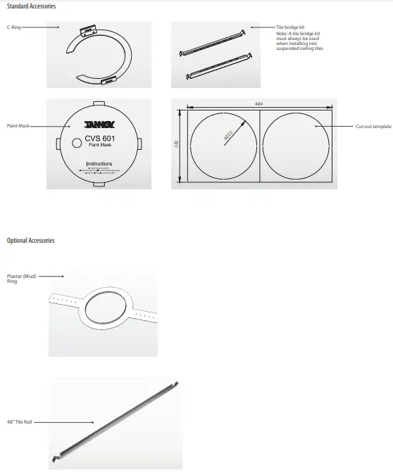
Every Tannoy product and accessory is carefully inspected before packing. After unpacking, please inspect your product to make sure no damage has occurred in transit. In the unlikely event of any damage, would you please notify your dealer immediately and retain your shipping carton, as your dealer may ask you to return the faulty unit to them for inspection.Each CVS loudspeaker is packed in pairs and provided with the following accessories as standard; C-Ring, tile-bridge kit, cut-out template, and paint mask. A plaster (mud) ring, 48″ tile rail are also available as an optional extra.
Safety Notices
Some regional construction codes require the use of a secondary method of securing loudspeakers in the ceiling to provide security of backup support. A secondary support line should be attached from the safety loop on the rear of the product to a source point on the ceiling. Please consult the relevant construction codes in your region.When using a power driver to install the product it is essential to use the correct torque level settings to avoid over-tightening and damage to the ceiling material or clamps.Recommended torque setting: 1.5 Nm.Tannoy will not be held responsible for any damages caused by the improper installation of these loudspeakers.
SAFETY NOTE:
In order to comply with the relevant hie safety regulations (ie. BS 5839:1998), it is required that in the event of a fire, that failure of the circuit to which the loudspeaker is connected does not o«ur before the evacuation of the building is complete. Suitable measures include: – a) use of terminal blocks (for connection to primary) with a melting point of not less than 6501, for example, constructed from (comic materials; b) use of terminal blocks of a lower left ing point but protected with thermal insulation; c) use of terminal blocks such that. on melting, an open-circuit or a short-circuit does not occur.
Product Feature Identification (CVS-601 shown)
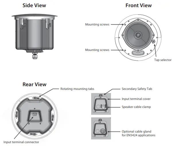
The auxiliary support ring is not shown
Accessories
Installation Guide for Suspended Ceilings
NOTE: The speaker images shown are for guidance only, and may not exactly represent your particular model.
- Remove the ceiling tile from its frame and place it on a flat surface. Mark the cut-out area on the ceiling tile by tracing around the template provided. (Fig.1)
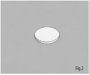
- Cut out the hole in the ceiling tile using a circular saw or pad saw (Fig.2). Place the C-ring and tile-bridge on top of the ceiling panel, align the C-ring over the hole, and screw the C-ring to the tile bridge using the fixings provided. (Fig.3)
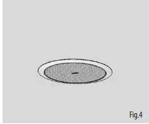
- Slide the speaker assembly through the hole and turn the screws on the front of the speaker to extend the mounting wings. Tighten the screws until a firm grip is achieved.If using a power driver, Tannoy recommends a torque setting of 1.5 Nm. (Fig.4)DO NOT OVERTIGHTEN!
- Slide the tile panel back into the suspended ceiling. The tile bridge ends will catch over the railings, supporting the weight of the speaker. (Fig.5)
- Connect a secondary support line to the safety tab. Some construction codes require the use of this secondary support point, which should connect to a separate secure support point using a suitable support line.Consult construction codes in your region.Go to page 15 for instructions on wiring and set-up instructions.
Installation Guide for Drywall Ceilings
NOTE: The speaker images shown are for guidance only, and may not exactly represent your particular model.
- Mark the cut-out area on the ceiling by tracing around the template provided. (Fig.1)
- Cut out the hole in the ceiling using a pad saw, then slide the C-Ring into the ceiling, aligning it over the cut-out hole. (Fig.2)
- Go to page 15 for wiring and set-up instructions then return to point 4 below.
- Connect a secondary support line to the safety tab. Some construction codes require the use of this secondary support point, which should connect to a separate secure support point using a suitable support line. Consult construction codes in your region.
- Slide the speaker assembly through the hole and turn the screws to extend the mounting wings. Tighten the screws until a firm grip is achieved.If using a power driver, Tannoy recommends a torque setting of 1.5 Nm. (Fig.3)DO NOT OVERTIGHTEN!
- Insert grille by pushing it onto the speaker.
Installation Instructions for Optional Plaster Ring
An optional plaster (mud) ring bracket is available from Tannoy. This bracket is designed to be pre-installed into newly constructed, non-suspended ceilings.NOTE: The speaker images shown are for guidance only, and may not exactly represent your particular model.
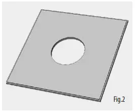
- Nail or screw the plaster ring to the joists. (Fig.1)
- Lay the speaker wiring to where the speaker will be fitted and complete the plastering work on the ceiling.
- Cut out the hole in the ceiling using a pad saw. (Fig.2)
- Go to page 15 for instructions on wiring then return to point 5 below.
- Connect a secondary support line to the safety tab. Some construction codes require the use of this secondary support point, which should connect to a separate secure support point using a suitable support line.Consult construction codes in your region.
- Slide the speaker assembly through the hole and turn the screws to extend the mounting wings.Tighten the screws until a firm grip is achieved.If using a power driver, Tannoy recommends a torque setting of 1.5 Nm. (Fig.3)DO NOT OVERTIGHTEN!
- Insert the grille by pushing it onto the speaker. (Fig.4)
Wiring and Setting Up
NOTE: The speaker images shown are for guidance only, and may not exactly represent your particular model.We recommend the use of insulated speaker wiring of between 12 and 18 AWG.WARNING: The power of the amplifier must be turned OFF when making connections to the loudspeakers.All connections must be checked before turning the amplifiers.
- Remove the wiring cover at the back of the speaker can access the removable Euro-type connector plug and socket.
- The speakers come with a standard speaker cable clamp (Fig.1), and an optional gland for EN5424 applications (Fig.2).(Please note that EN5424 does not cover the CVS 801S and CVS801SLZ subwoofers.)
- Feed the cable through and attach to the Euro-type connector (Fig.3). ‘
- For connection to an amplifier, use Pins 1 and 2 (Figs.3, 4, 5):• Make sure that the wiring polarity is correct, where:• Pin 1 is positive• Pin 2 is negativeFor connection to additional speakers in a distributed line (Fig.4)Pins 3 and 4 are used to loop thru to additional speakers:• Make sure that the wiring polarity is correct, where:• Pin 3 is positive• Pin 4 is negative
- Tighten the cable clamp or cable gland and plug in the Euro-type connector to the loudspeaker. Replace the rear cover and securely tighten the supplied screws.
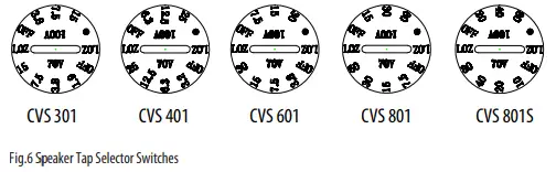
- The speaker is fitted with a multi-tap transformer for use in distributed-line systems (Fig.6). There is also a LOZ tap. Select the required tap before pushing the grill in place. The average impedance of each speaker in this range is 8 Ohms in the LOZ setting.CAUTION: THE SPEAKER IS SUPPLIED IN LOW IMPEDANCE MODE. NEVER CONNECT THE SPEAKER TO A 70/100 VOLT AMPLIFIER WHILE THE SPEAKER IS SETFOR LOW IMPEDANCE (LOZ).

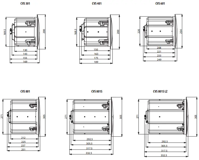
Dimensions (mm)
Specifications
| (VS 301 | N. com | (Y5601. | (YS 801 | V CVS801S | cossonCZ | |
| Performance | ||||||
| Frequency response (+3dB, -3 dB) | 85 Hz-19 kHz | •102 Hz-20 kHz | 105 Hz-20 kHz | lk88 Hz-20 kHz | fib 66 Hz-200 Hz | 66 Hz-200 Hz |
| Frequency response (-10 dB) | 68 Hz-20 Hz | 70 Hz-20 kHz | 74 Hz-20 Hz | 65 Hz-20 kHz | 53 Hz-200 Hz | 5311z-200 Hz |
| Sensitivity at 1m/1W | 85 dB | 84 dB | 90dB | 90 dB | 92dB | 92dB |
| Directivity factor (Q) averaged 1 kHz to 6 kHz | 4. | 5. | 7. | 10. | N/A | N/A |
| Directivity Index (DI) averaged 1 kHz to6 kHz | 6. | 7. | 9. | 10. | N/A | N/A |
| Power handling (LoZ) *1 Average | 20W | 30W | SOW | 90W | 100W | 100W |
| Program | 40W | 60W | 100W | 180W | 200W | 200W |
| Peak | 80W | 120W | 200W | 360W | 400W | 400W |
| Recommended amplifier power | 100 0 | 200 W @8 0 | ||||
| Nominal Impedance (Switch to LoZ) | 80 | 80 | 80 | 80 | 80 | 80 |
| Rated maximum WL (1 in, Switch to LoZ) | 101 dB | 102 dB | 110dB | 113 dB | 115 dB | 115 dB |
| Average | 98 d8 | 99 dB | 107 dB | 110dB | 112 dB | 112dB |
| Peak 91 | 104 dB | 105 dB | 113 dB | 116dB | 118 dB | 118dB |
| Transformer taps 70V | 15 W/7.5 W/3.8W/1.9W | 25 W/123 W/6.3 W/3.2 W | 30W/15 W/7.5 W/3.8 W | 60W/30W/15 W/7.5 W | 80 W/40 W/20 W/10 W | N/A |
| 100 V | 15 W/7.5 W/3.8 W | 25 W/12.5 W/63 W | 30 W/15 W/7.5 W | 60W/30W/15 W | 80W/40W/20 W | N/A |
| Coverage angles | ||||||
| 500 Hz | 180° | 180° | 180° | 180° | N/A | N/A |
| 1 kHz | Horizontal: 133°;Vertical: 130° | Horizontal: 125°;Vertical: 118° | Horizontal: 124°;Vertical: 124° | Horizontal: 106°;Vertical: 118° | N/A | N/A |
| 2 kHz | Horizontal: 79°;Vertical: 82° | Horizontal: 82°;Vertical: 81° | Horizontal:800;Vertical: 76° | Horizontal: 124°;Vertical: 107° | N/A | N/A |
| 4 kHz | Horizontal: 155°;Vertical: 166° | Horizontal: 88°;Vertical:86° | Horizontal: 76°;Vertical:92° | Horizontal: 63°;Vertical:65° | N/A | N/A |
| Transducers Low frequency | 76 mm (3″) PP cone | 100 mm (4″) PP cone | 165 mm (6.5″) PP cone | 200 mm (8″) PP cone | 200 mm (8″) Paper cone | 200 mm (8″) Paper cone |
| High frequency | N/A | 20 mm (0.79″)coaxially mounted | 20 mm (0.7r)coaxially mounted | 25 mm (1″)coaxially mounted | N/A | N/A |
| Physical | ||||||
| Enclosure | Blind mount (BM) | Blind mount (BM) | Blind mount (BM) | Blind mount (BM) | Blind mount (BM) | Blind mount (BM) |
| Back can | Anodized steel | Anodized steel | Anodized steel | Anodized steel | Anodized steel | Anodized steel |
| Baffle | Reflex loadedUL 94V-0 rated ABS | Reflex loadedUL 94V-0 rated ABS | Reflex loadedUL 94V-0 rated ABS | Reflex loadedUL 94V-0 rated ABS | Reflex loadedUL 94V-0 rated ABS | Reflex loadedUL 94V-0 rated ABS |
| Grille | Aluminum,powder coated | Aluminum,powder coated | Aluminum,powder coated | Aluminum,powder coated | Aluminum,powder coated | Aluminum,powder coated |
| Safety features | Rear enclosuresafety ring forload-bearing bond | Rear enclosuresafety ring forload-bearing bond | Rear enclosuresafety ring forload-bearing bond | Rear enclosuresafety ring forload-bearing bond | Rear enclosuresafety ring forload-bearing bond | Rear enclosuresafety ring forload-bearing bond |
| Clamping design | Security toggle clamp | Security toggle clamp | Security toggle clamp | Security toggle clamp | Security toggle clamp | Security toggle clamp |
| Connectors | Euroblock-styleconnector withscrew terminals(with input cover andcable gland supplied) | Euroblock-styleconnector withscrew terminals(with input cover andcable gland supplied) | Euroblock-styleconnector withscrew terminals(with input cover andcable gland supplied) | Euroblock-styleconnector withscrew terminals(with input cover andcable gland supplied) | Euroblock-styleconnector withscrew terminals(with input cover andcable gland supplied) | Euroblock-styleconnector withscrew terminals(with input cover andcable gland supplied) |
| Dimensions | ||||||
| (grille max diameter) | 200 mm (8″) | Bezel diameter~ 200 mm (8″) | 254 mm (10″) | 305 mm (12″) | 305 mm (121 | 305 mm (12″) |
| The rear face of the baffle to the rear of the back can | 130 mm (5121 | 150 mm (5.91″) | 208 mm (8.19″) | 212 mm (8.35″) | 292.50 mm (11.521 | 292.50 mm (1132″) |
| The rear face of the baffle to the top of the safety loop | 143 mm (5.631 | 163 mm (6.42″) | 221 mm (8.701 | 225 mm (8.86″) | 305.5 mm (12.03″) | 305.5 mm (12.03″) |
| The rear face of the baffle to the rear of flex conduit | 155 mm (610″) | 175 mm (6.89″) | 233 mm (917) | 237 mm (9.33″) | 317.5 mm (12.5″) | 317.5 mm (12.5″) |
| Hole cutout diameter | 9172 mm (6.77″) | 9172 mm (6.77″) | 9222 mm (8.74″) | 9273 mm (10.75″) | 0273 mm (10.75″) | 0273 mm (1025″) |
| Net weight | 2.41 kg (5.30 Ibs) ±10% | 2.77 kg (6.09 Ibs) ±10% | 3.8 kg (8.36 Ibs) ±10% | 5.35 kg (11.77 Ibs) ±10% | 7.93 kg (17.45 Ibs) ±10% | 7 kg (15.4 Ibs) ±10% |
| Included accessories | Metal grille, cablegland, flex conduit,(-ring, tile-bridge kit,paint mask,cutout template | Metal grille, cablegland, flex conduit,C-ring, tile-bridge kit,paint mask,cutout template | Metal grille, cablegland, flex conduit,C-ring, tile-bridge kit,paint mask,cutout template | Metal grille, cablegland, flex conduit,C-ring, tile-bridge kit,paint mask,cutout template | Metal grille, cablegland, flex conduit,C-ring, tile-bridge kit,paint mask,cutout template | Metal grille, cablegland, flex conduit,C-ring, tile-bridge kit,paint mask,cutout template |
| Optional accessories | Mud ring48″ Tile rail | Mud ring48″ Tile rail | Mud ring48″ Tile rail | Mud ring48″ Tile rail | Mud ring48″ Tile rail | Mud ring48″ Tile rail |
| Packed quantity | 1 pair | 1 pair | 1 pair | 1 pair | 1 pair | 1 pair |
*1 Average power rating is under IEC-shaped pink noise with a 6dB crest factor for 100 hours continuously.
Other important information
- Register online. Please register your new Music Tribe equipment right after you purchase it by visiting tannoy.com. Registering your purchase using our simple online form helps us to process your repair claims more quickly and efficiently. Also, read the terms and conditions of our warranty, if applicable.
- Malfunction. Should your Music Tribe Authorized Reseller not be located in your vicinity, you may contact the Music Tribe Authorized Fulfiller for your country listed under “Support” at tannoy.com. Should your country not be listed, please check if your problem can be dealt with by our “Online Support” which may also be found under “Support” at tannoy.com. Alternatively, please submit an online warranty claim at tannoy.com BEFORE returning the product.
report this adReferences
[xyz-ips snippet=”download-snippet”]