![]()
Quick Start Guide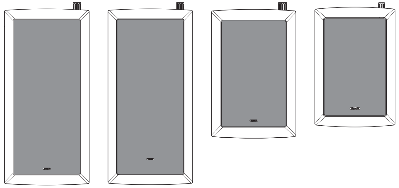 iW SeriesiW 62S-WH2 x 6″ In-Wall Subwoofer (White)iW 62DS-WH3 Way 6″ In-Wall Loudspeaker (White)iW 6DS-WH2 Way 6″ In-Wall Loudspeaker (White)iW 4DC-WH2 Way 4″ Dual Concentric In-Wall Loudspeaker (White)
Important Safety Instructions

 Terminals marked with this symbol carry an electrical current of sufficient magnitude to constitute a risk of electric shock.Use only high-quality professional speaker cables with ¼” TS or twist-locking plugs pre-installed. All other installation or modifications should be performed only by qualified personnel. This symbol, wherever it appears, alerts you to the presence of uninsulated dangerous voltage inside the enclosure – voltage that may be sufficient to constitute a risk of shock.
![]() This symbol, wherever it appears, alerts you to important operating and maintenance instructions in the accompanying literature. Please read the manual.
This symbol, wherever it appears, alerts you to important operating and maintenance instructions in the accompanying literature. Please read the manual.![]() CautionTo reduce the risk of electric shock, do not remove the top cover (or the rear section).No user-serviceable parts inside. Refer servicing to qualified personnel.
CautionTo reduce the risk of electric shock, do not remove the top cover (or the rear section).No user-serviceable parts inside. Refer servicing to qualified personnel.![]() CautionTo reduce the risk of fire or electric shock, do not expose this appliance to rain and moisture. The apparatus shall not be exposed to dripping or splashing liquids and no objects filled with liquids, such as vases, shall be placed on the apparatus.
CautionTo reduce the risk of fire or electric shock, do not expose this appliance to rain and moisture. The apparatus shall not be exposed to dripping or splashing liquids and no objects filled with liquids, such as vases, shall be placed on the apparatus.![]() CautionThese service instructions are for use by qualified service personnel only.To reduce the risk of electric shock do not perform any servicing other than that contained in the operation instructions. Repairs have to be performed by qualified service personnel.
CautionThese service instructions are for use by qualified service personnel only.To reduce the risk of electric shock do not perform any servicing other than that contained in the operation instructions. Repairs have to be performed by qualified service personnel.
- Read these instructions.
- Keep these instructions.
- Heed all warnings.
- Follow all instructions.
- Do not use this apparatus near water.
- Clean only with dry cloth.
- Do not block any ventilation openings. Install in accordance with the manufacturer’s instructions.
- Do not install near any heat sources such as radiators, heat registers, stoves, or other apparatus (including amplifiers) that produce heat.
- Do not defeat the safety purpose of the polarized or grounding-type plug. A polarized plug has two blades with one wider than the other. A grounding-type plug has two blades and a third grounding prong. The wide blade or the third prong are provided for your safety. If the provided plug does not fit into your outlet, consult an electrician for the replacement of the obsolete outlet.
- Protect the power cord from being walked on or pinched particularly at plugs, convenience receptacles, and the point where they exit from the apparatus.
- Use only attachments/accessories specified by the manufacturer.

- Use only with the cart, stand, tripod, bracket, or table specified by the manufacturer, or sold with the apparatus. When a cart is used, use caution when moving the art/apparatus combination to avoid injury from tip-over.
- Unplug this apparatus during lightning storms or when unused for long periods of time.
- Refer all servicing to qualified service personnel.Servicing is required when the apparatus has been damaged in any way, such as power supply cord or plug is damaged, liquid has been spilled or objects have fallen into the apparatus, the apparatus has been exposed to rain or moisture, does not operate normally, or has been dropped.
- The apparatus shall be connected to a MAINS socket outlet with a protective earthing connection.
- Where the MAINS plug or an appliance coupler is used as the disconnect device, the disconnect device shall remain readily operable.
- Correct disposal of this product: This symbol indicates that this product must not be disposed of with household waste, according to the WEEE Directive (2012/19/EU) and your national law. This product should be taken to a collection center licensed for the recycling of waste electrical and electronic equipment (EEE). The mishandling of this type of waste could have a possible negative impact on the environment and human health due to potentially hazardous substances that are generally associated with EEE. At the same time, your cooperation in the correct disposal of this product will contribute to the efficient use of natural resources. For more information about where you can take your waste equipment for recycling, please contact your local city office or your household waste collection service.
- Do not install in a confined space, such as a bookcase or similar unit.
- Do not place naked flame sources, such as lighted candles, on the apparatus.
- Please keep the environmental aspects of battery disposal in mind. Batteries must be disposed of at a battery collection point.
- This apparatus may be used in tropical and moderate climates up to 45°C.


LEGAL DISCLAIMERMusic Tribe accepts no liability for any loss which may be suffered by any person who relies either wholly on or in part upon any description, photograph, or statement contained herein. Technical specifications, appearances, and other information are subject to change without notice. All trademarks are the property of their respective owners. Midas, Klark Teknik, Lab Gruppen, Lake, Tannoy, Turbosound, TC Electronic, TC Helicon, Behringer, Bugera, Oberheim, Auratone, Aston Microphones and Coolaudio are trademarks or registered trademarks of Music Tribe Global Brands Ltd. © MusicTribe Global Brands Ltd. 2021 All rights reserved.LIMITED WARRANTYFor the applicable warranty terms and conditions and additional information regarding Music Tribe’s Limited Warranty, please see complete details online at musictribe.com/warranty.
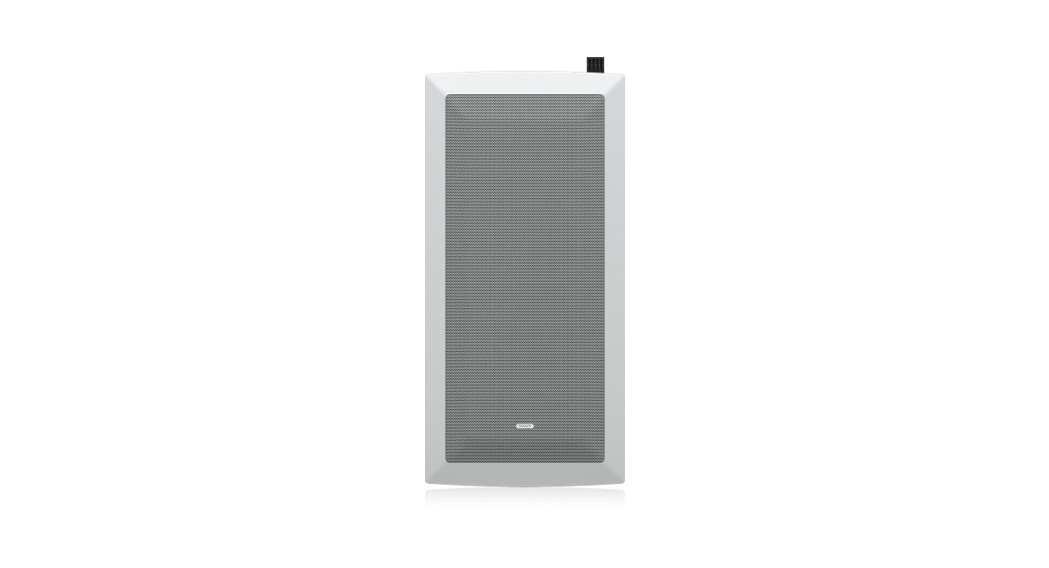
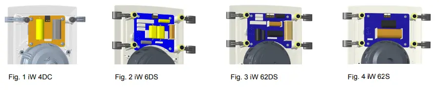
Product Feature Identification

iW62 BackcanThe optional pre-install back can for iW 62DS-WH and iW 62S-WH models. The back comes with its own installation instructions.
Accessories
Installation Templates (supplied)

Wiring and Setting Up
Terminal Panel Connections and Driver Earthing
- WARNING: To avoid potential damage to your loudspeaker, ensure that the amplifier is switched OFF prior to connecting or disconnecting any cables.
- Before switching the amplifier ON, double-check that all connections are secure and that the polarity is correct.
ConnectionThe screw terminals are designed to take the loudspeaker cable of AWG24 to AWG12 in size.
- Strip off approximately 8 mm (1/4″) of the outer protective layer and twist the inner cores together. Insert the core and use a small flat screwdriver to secure, ensuring that correct polarity is maintained see Figs 1 to 3.
- Run cabling from one pair of speaker terminals, back to the amplifier, ensuring the correct polarity. The other set of terminals are a link that can be run to another speaker.
Connection of Earth or Ground Lead – iW 6DS and iW 62DS
- The iW 6DS and iW 62DS models have an extra terminal designed to optimize performance further by taking advantage of the driver earthing facility. Use a shielded or screened loudspeaker cable; connecting the screening termination to the earth or ground (green) terminal on the loudspeaker and to the ground or earth connection on the amplifier.
- Alternatively, if you are not using a screened loudspeaker cable but wish to utilize the earthing facility, run a single cable between the earth or ground (green) terminalon the loudspeaker to the earth (ground) connection on the amplifier.
- Switch the amplifier on with the volume control set at its lowest setting. Select a favorite source and slowly turn up the volume to a low level. Check that bass andtreble information is being reproduced from the speaker. If not, switch off the amplifier and recheck the connections.
Connecting the iW 62S
- The iW 62S may be operated in either passive or active mode.
- In passive mode, the internal low pass filters provide the transition to the main speakers.
- In active mode, the internal low pass filters are bypassed, to allow the use of an external controller and power amplifier. This mode of operation is preferred foroptimum performance, as it allows low-frequency extension and equalization to be applied, and the low pass crossover to be optimally configured to the main speak setup and room characteristics.
- The passive or active operation can be set by the front baffle switch, behind the grille.
- Run cabling from one pair of speaker terminals, back to the amplifier, ensuring the correct polarity. The other set of terminals are a link that can be run to another speaker.
Installation Guide
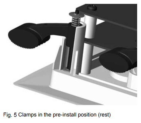
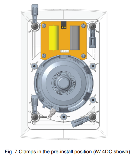
Wall Clamp MechanismA unique clamping mechanism has been designed to provide an acoustically optimum bond to the wall surface without risk of distortion to the loudspeaker baffle. The iW 4DC has four mounting clamps and screws, the iW 6DS has six, and the iW 62DS and iW 62S have eight. As these screws are tightened, the immensely strong polycarbonate clamping arms will automatically swing round into the locking position, locating securely to the inside of the wall surface.The design also allows for simple removal or reorientation of the loudspeaker. The spring-loaded clamp mechanism ensures that as the screws loosened (turned anticlockwise)the clamp arm travels along its guide before turning itself into the rest position. The captive locking system ensures that the clamp arm cannot drop off the end of the screw tobe lost in the wall cavity.IMPORTANT Get all the clamps in the rest position by loosening all screws before attempting to remove the speaker from the wall.
InstallationWARNING: If adding new speakers to an existing installation, or simply replacing old ones, you must ensure that the amplifier driving the system is switched OFF. WARNING: Prior to proceeding with the installation, ensure that you accurately determine the position of electrical cabling, pipework and wall studs. Having selected a wall location clear of any obstruction, measure carefully to ensure the correct placement.
 PaintingBefore proceeding with the installation, the grille and baffle panel can be painted to blend with the surrounding decor.When painting the baffle, be sure to carefully mask off the driver assemblies. It is important to ensure that paint does not come into contact with the cone, roll surround or HF unit. It is strongly recommended that the metal perforated grille is sprayed as this will avoid clogging of the holes. If painting with a brush is the only option, then several thin coats of paint will provide a superior finish to that achieved by one applied too thickly.The speaker is supplied with a sheet of acoustically transparent protective foam fixed to the inside of the grille. Having painted the grille to match the room decor please remove the original foam and replace with the spare sheet supplied in the accessory pack. It is important that this replacement foam is bonded to the grille over it’s entire area, using a suitable spray adhesive. Failure to do so will result in audible resonance.OverviewTannoy In-wall loudspeakers have been designed for installation into standard stud partition wall systems constructed with 102 by 51 mm (4″ by 2″) timber at 406 mm (16″) centers. However, it is envisaged that they will generally be used in cavity wall installations constructed with standard thickness plasterboard. These are guidelines and therefore do not preclude the use of the Tannoy In-wall products in different locations and a wide range of other wall construction types, as long as they have a secure clamping surface up to a maximum thickness of 25.4 mm (1″).Driver cone movement at low frequencies may become excessive unless steps are taken in the wall cavity void behind the loudspeaker to provide a well-sealed and accurately controlled rear ‘enclosure’ volume. This will effectively act as an enclosure behind the speaker (see Speaker Loading Volume section in this manual).Failure to ensure this, will affect the bass and midrange performance unfavorably.
PositioningThere is a great deal of mounting location flexibility with these models when used in home cinema or multi-channel systems. In particular, please note that due to the unique point source symmetrical dispersion properties of the Tannoy Dual Concentric drive unit, the model iW4 DC and iW 6DS can be mounted in either portrait (in stud partition wall situations) or landscape positions, where sufficient space exists behind the wall surface.To achieve the optimum spectral and stereo performance select your mounting location as follows:Vertical planeAlign the front baffle centers at the intended listening height, usually dictated by the normal seated listening position. For audio use, when positioned in front of the listener, this will usually be in the height range of 1100 mm to 1700 mm (43″ to 67″). For use as home cinema rear effects speakers mounted on the rear walls of the room, the mounting height range is 1530 mm to 2140 mm (60″ to 84″).Horizontal planeThe loudspeakers should be located between 1500 mm to 4500 mm (60″ to 180″) apart. The room size and shape will dictate the final mounting location, but generally, the listening position, when used as a stereo pair, should be set slightly further away than the speakers are apart.When used as rear effects speakers in a home cinema system, the ideal viewing point will establish the distance from the rear wall to the listening position. Avoid positioning the loudspeakers in corners of the room, as this will have a negative effect on performance; maintain a distance of 1 m (39″) away from a corner.Speaker Fitting
Remember… Measure twice – cut once!
- Once the mounting location has been selected, use the template provided to mark out the area of wall material to be cut out. Carefully remove the waste, checking again that there are no interferences from studs/wire/pipes etc.
- Install the loudspeaker cabling ensuring that the wiring route is laid clear of all screws and nails that could potentially damage the cable insulation. Allow sufficient cable length at the speaker end to allow for an unrestricted connection.
- It is necessary to block off the void behind the speaker by suitable means (insulation material or foam) to create an “enclosure” area. This will offer the speaker the required loading volume as detailed in the specification section of this manual.
- It is important to provide some acoustic damping between the speaker and the rear wall surface. We recommend the use of a BAF sheet (Bonded Acrylic Fibre). Ensure that all materials used comply with local fire and building regulations.
- Strip 8 mm (1/4 inch) of shielding from the end of the speaker cables in preparation for connection to the terminals on the rear of the speaker.
- Check that the clamping arms are aligned as shown prior to insertion in the wall.
- Connect the speaker cable observing the correct wiring polarity. The positive terminal (marked + and colored red) should receive the positive cable (usually marked with a repeated stamped name, line or raised rib) and the negative terminal (marked – and colored black) the negative cable.
- Insert the baffle into the pre-prepared hole in the wall, ensuring that the speaker wire is located securely away from the driver, as contact with the driver cone will cause annoying buzzes.
- Each of the clamp screws can now be tightened (clockwise). Starting at one corner then move to the opposite corner, tightening sufficiently to check for visual orientation, before proceeding to tighten the other two corners.
- Finish off by tightening the middle clamps. WARNING: Do not over tighten the screws – this is unnecessary to achieve a strong acoustic seal to the wall, and risks damaging the wall surface
- Repeat the installation procedure for the other loudspeakers and complete the connection process to the amplifier.
- Once again ensure that correct cable polarity is observed.
- Switch on the amplifier with the volume control at its lowest setting. Select a signal source and slowly turn up the volume to a low level. Check that bass and treble information comes from both speakers – if not, switch off the amplifier and recheck the connections.
- Carefully check the area surrounding the installation and ensure that there are no buzzes or rattles that could potentially impair enjoyment of the system. If there are, then locate and silence the causes using cable ties or suitable packing material.
- Optimum performance will be assisted by the use of silicone sealant to seal gaps between the studs and the wallboard material. This cavity sealing will help to create a near-airtight seal. Do not silicone the baffle to the wall as the clamping mechanism creates an effective bond.
 WARNING: Do not over tighten the screws – this is unnecessary to achieve a strong acoustic seal to the wall, and risks damaging the wall surface
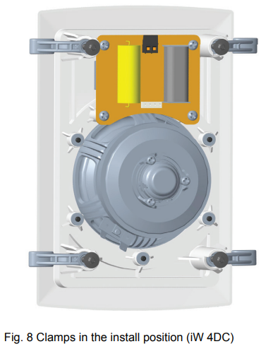
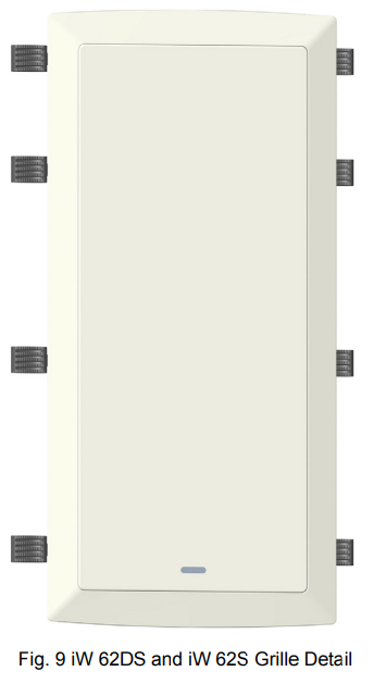
Grille Fitting and RemovalThe grille should be carefully fitted to the front baffle aperture, by lining up the edges of the grille carefully with the baffle. To avoid indentation damage, do not press the center of the grille; apply even pressure to the corner as it is pressed firmly into position.To remove the grille, loop an opened paper clip or a similar length of firm wire, through two holes near a corner and pull gently. The grille is intended to be a tight fit, so insert the wire at each corner in turn, pulling carefully to avoid distortion of the mesh.
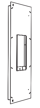
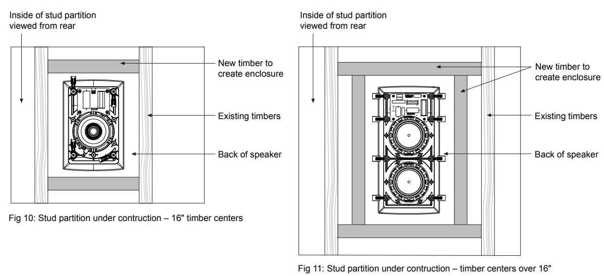
 Speaker Loading VolumeThere are two simple approaches to achieve a sealed ‘enclosure’ to provide the correct driver loading area behind the speaker.The chosen method will depend on whether the wall is under construction, as in a new building project, or an existing wall where access is limited.Option 1 Stud partition walls under construction, with 102 mm by 51 mm (4 by 2 inch) timber at 406 mm (16 inches) centers.
- Block off the cavity, above and below the intended speaker opening, with the same framing timber.The distance between these two internal barriers should be as shown in this table:
| Model | Distance |
| iw4 DC | 410 mm (16″) |
| iW 6DS | 550 mm (21.5″) |
| iW 62DS | 825 mm (32.5″) |
| iW 62S | 825 mm (32.5″) |
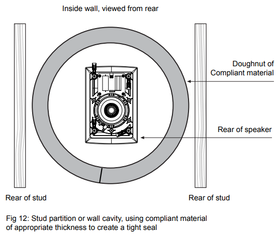
 Option 2Existing timber stud partition, or any other wall type constructed with a 102 mm (4 inch) cavity depth.
- Many professional installers use a “doughnut’ of compliant material, which can be inserted as a tight fit between the two surfaces of the partition or into the wall cavity. The length of the internal surface of the strip of material determines the ‘enclosure’ volume. For each model, cut the strips into lengths listed in the table below, insert into the cavity, and join to form a ring that will ensure the correct volume – see Fig : 12
| Model | Length |
| iW4 DC | 1380 mm (54″) |
| iW 6DS | 1570 mm (62″) |
| iW 62DS | 1920 mm (75 1/2″) |
| iW 62S | 1920 mm (75 1/2″) |
iW4 DC Model Dimensions
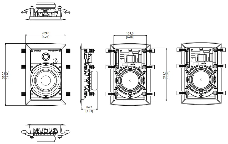
iW 6DS Model Dimensions
 iW 6DS Model Dimensions
iW 62DS Model Dimensions
 iW 62DS Model Dimensions
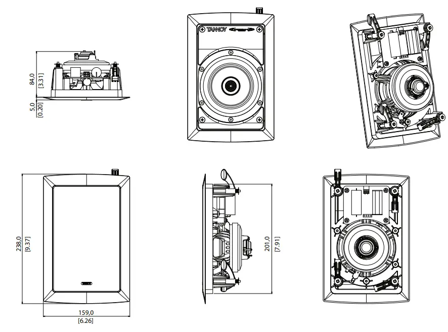
iW 62S Model Dimensions

Technical Specifications
| iW 62S-WH | iW 62DS-WH | iW 6DS-WH | iW 4DC-WH | iW 62 BACKCAN | |
| Perform’s: | Passive: 29 Hz- 110 Hz;Active: determinedby controller | 70 Hz – 20 kHz | 75 Hz – 20 kHz | 88 Hz – 51 kHz | |
| Frequency response (±3 dB) (see note 3) | |||||
| Frequency response (-10 dB) | 34 Hz – 20 kHz | 36 Hz -20 kHz | 73 Hz – 54 kHz | ||
| Low-frequency alignment (-6dB) | 29 Hz | 34 Hz | 36 Hz | 73 Hz | |
| Power handling (see note 1) | 160 W continuous,640 W peak | 80 W continuous,320 W peak | W continuous, 280 W peak | 60 W continuous,240 W peak | |
| Recommended amplifier power | 100 -320 W (total) | 20- 120 W @ 8 0 | |||
| System sensitivity (see note 2) | 94 dB (2.83 1 m) | 92 dB (2.83 V @ 1 m) | 89 dB(2.83 1 m) | 88 dB (2.83 V @ 1 m) | |
| Nominal impedance | 40 | 80 | |||
| Rated maximum SPL | 116 dB continuous,122 dB peak | 111 dB continuous,117 dB peak | 107 dB continuous,113 dB peak | 106 dB continuous,112 dB peak | |
| Crossover | Passive, 2nd orderlow-pass | Passive, 2nd order LF, 1stand 2nd order band-passmid, 2nd order HF | Passive, 2nd order LF,2nd order HF | Passive, 2nd order LF,2nd order HF | |
| Crossover point | Passive: 110 Hz; Active:determined by controller | 500 Hz, 1.5 kHz | 1.7 kHz | 1.7 kHz | |
| Crossover HF adjustment | NA | -±1.5 dB | -±1.5 dB | NA | |
| Transducers | |||||
| High frequency | 25 mm (1″) 25-micronneodymium | titanium dome, magnet system | 19 mm (0.75″) titaniumdome, neodymiummagnet system | ||
| Low frequency | 2 x 165 mm (6.51 m fiber paper pulp cone | 165 mm (6.5″) multifibrepaper pulp cone | 100 mm (4.0″) multifibrepaper pulp mid-bass cone | ||
| Wiring | Positive 1, positive 2,negative 1, negative 2 | Positive 1, positive 2negative 1, negative 2ground | Positive, negative,ground | Positive, negative | |
| Physical | |||||
| Dimensions HWD | 473.5 x 227 x 110.5 mm(18.7 x 8.9 x 4A”) | 473.5 x 227 x 92 mm(18.6 x 8.9 x 3.6) | 320 x 209 x 90 mm(12.6 x 8.2 x 3.5″) | 238 x 159 x91mm (9.4 x 6.3 x 3.6″) | 1200 x 451 x 97 mm(47.2 x 17.8 x3.8″) |
| Mounting depth | 102 mm (41 | 99 mm (3.9″) | 88 mm (3.41 | ||
| Net weight | 5.8 kg (12.81b) | 4.2 kg (9.3 lb) | 2.2 kg (4.9 lb) | 1.3 kg (2.91b) | 8.6 kg (19.0 lb) |
| Construction | Baffle panel: molded UV Resistant ABS, Clamps: molded polycarbonate | Cabinet panel: SECC | |||
| Finish | White, paintable | ||||
| Grille | Powder-coated perforated steel |
Notes:
- Long-term power handling capacity as defined in IEC standard IEC268-5
- Averaged over specified bandwidth for the half-space environment. For anechoic conditions, the figure is to be decreased by 3 dB
- ± 3dB, measured at 1 meter in an anechoic chamber in a critically tuned enclosure.
- Remove links when bi-amping or bi-wiring
- Remove links in stereo operation
Other important information
Important information
- Register online. Please register your new music Tribe equipment right after you purchase it by visiting musictribe.com. Registering your purchase using our simple online form helps us to process your repair claims more quickly and efficiently. Also, read the terms and conditions of our warranty, if applicable.
- Malfunction. Should your Music Tribe Authorized Reseller not be located in your vicinity, you may contact the Music Tribe Authorized Fulfiller for your country listed under “Support” at musictribe.com.Should your country not be listed, please check if your problem can be dealt with by our “Online Support” which may also be found under “Support” at musictribe.com.Alternatively, please submit an online warranty claim at musictribe.com BEFORE returning the product.
- Power Connections. Before plugging the unit into a power socket, please make sure you are using the correct mains voltage for your particular model. Faulty fuses must be replaced with fuses of the same type and rating without exception.
![]()
References
[xyz-ips snippet=”download-snippet”]