![]()
Quick Start Guide
SAT 3Surface Mount Satellite Loudspeaker for Commercial ApplicationsSAT SUBCompact Wall Mount Subwoofer for Commercial ApplicationsSAT SUB 4 PACKPackaged Satellite-Subwoofer Loudspeaker System for Commercial ApplicationsV 1.0
Important Safety Instructions
 Terminals marked with this symbol carry an electrical current of sufficient magnitude to constitute a risk of electric shock. Use only high-quality professional speaker cables with ¼” TSor twist-locking plugs pre-installed. All other installation or modifications should be performed only by qualified personnel. This symbol, wherever it appears, alerts you to the presence of uninsulated dangerous voltage inside the enclosure- voltage that may be sufficient to constitute a risk of shock.
 This symbol, wherever it appears, alerts you to important operating and maintenance instructions in the accompanying literature. Please read the manual. Caution To reduce the risk of electric shock, do not remove the top cover (or the rear section). No user-serviceable parts inside refer servicing to qualified personnel. Caution To reduce the risk of fire or electric shock, do not expose this appliance to rain and moisture. The apparatus shall not be exposed to dripping or splashing liquids and no objects filled with liquids, such as vases, shall be placed on the apparatus. CautionThese service instructions are for use by qualified service personnel only. To reduce the risk of electric shock do not perform any servicing other than that contained in the operation instructions repair has to be performed by qualified service personnel.
- Read these instructions.
- Keep these instructions.
- Heed all warnings.
- Follow all instructions.
- Do not use this apparatus near water.
- Clean only with dry cloth.
- Do not block any ventilation openings. Install in accordance with the manufacturer’s instructions.
- Do not install near any heat sources such as radiators, heat registers stores, or other apparatus (including amplifiers) that produce heat.
- Do not defeat the safety purpose of the polarized or grounding-type plug. A polarized plug has two blades with one wider than the other.A grounding-type plug has two blades and a third grounding prong. The wide blade or the third prong are provided for your safety. If the provided plug does not fit into your outlet, consult an electrician for the replacement of the obsolete outlet.
- Protect the power cord from being walked on or pinched particularly at plugs, convenience receptacles, and the point where they exit from the apparatus.
- Use only attachments/accessories specified by the manufacturer.
 Use only with the cart, stand, tripod, bracket, or table specified by the manufacturer, or sold with the apparatus. When a cart is used, use caution when moving the cart/ apparatus combination to avoid injury from tip-over.
- Unplug this apparatus during lightning storms or when unused for long periods of time.
- Refer all servicing to qualified service personnel. Servicing is required when the apparatus has been damaged in any way, such as power supply cord or plug is damaged, liquid has been spilled or objects have fallen into the apparatus, the apparatus has been exposed to rain or moisture, does not operate normally, or has been dropped.
- The apparatus shall be connected to a MAINS socket outlet with a protective earthing connection.
- Where the MAINS plug or an appliance coupler is used as the disconnect device, the disconnect device shall remain readily operable.
- Correct disposal of this product: This symbol indicates that this product must not be disposed of with household waste, according to the WEEE Directive (2012/19/EU) and your national law. This product should be taken to a collection center licensed for the recycling of waste electrical and electronic equipment (EEE). The mishandling of this type of waste could have a possible negative impact on the environment and human health due to potentially hazardous substances that are generally associated with EEE. At the same time, your cooperation in the correct disposal of this product will contribute to the efficient use of natural resources. For more information about where you can take your waste equipment for recycling, please contact your local city office or your household waste collection service.
- Do not install in a confined space, such as a bookcase or similar unit.
- Do not place naked flame sources, such as lighted candles, on the apparatus.
- Please keep the environmental aspects of battery disposal in mind. Batteries must be disposed of at a battery collection point.
- This apparatus may be used in tropical and moderate climates up to 45°C.
 Use only with the cart, stand, tripod, bracket, or table specified by the manufacturer, or sold with the apparatus. When a cart is used, use caution when moving the cart/ apparatus combination to avoid injury from tip-over.
LEGAL DISCLAIMER
Music Tribe accepts no liability for any loss which may be suffered by any person who relies either wholly on or in part upon any description, photograph, or statement contained herein. Technical specifications, appearances, and other information are subject to change without notice.All trademarks are the property of their respective owners. Midas, Klark Teknik, Lab Gruppen, Lake, Tannoy, Turbosound, TC Electronic, TC Helicon, Behringer, Bugera, Auratone, and Coolaudio are trademarks or registered trademarks of Music Tribe Global Brands Ltd.© Music Tribe Global Brands Ltd. 2020 All rights reserved.
LIMITED WARRANTY
For the applicable warranty terms and conditions and additional information regarding Music Tribe’s Limited Warranty, please see complete details online at musictribe.com/warranty.
Introduction
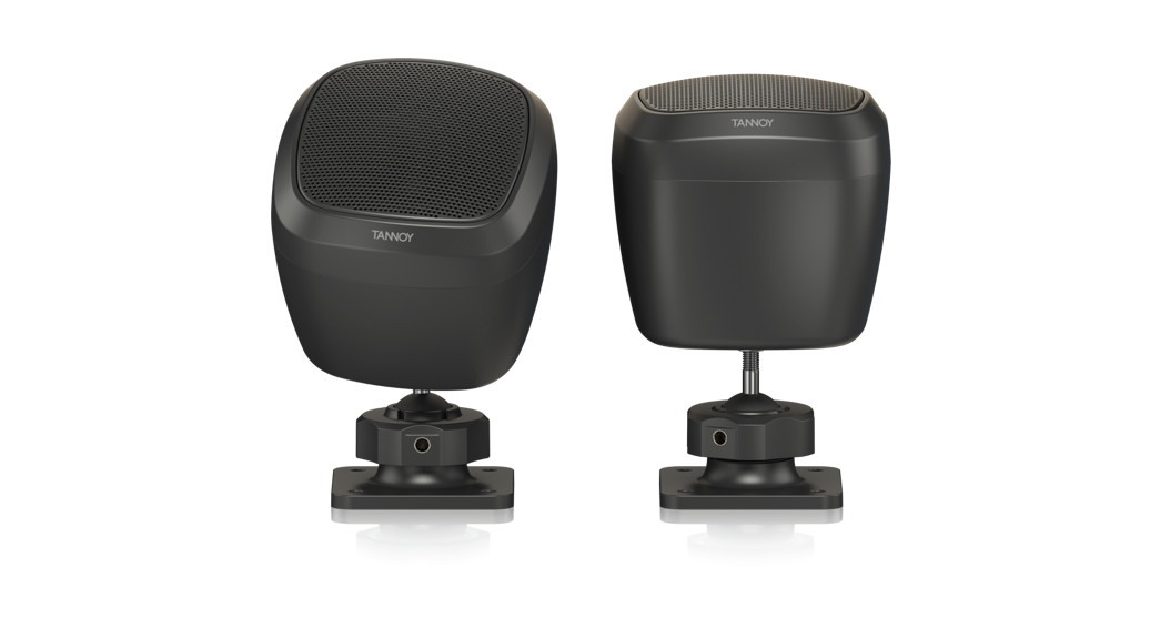
Thank you for purchasing this TANNOY loudspeaker. This product range is ideal for both background and foreground music in bars, restaurants and shops. It has a simple plug-and-play deployment, with no external processing required. The SAT 3 satellite speakers connect to the SAT SUB subwoofer
Features
SAT SUB
- Slimline 6.5″ subwoofer
- Integrated crossover and terminals for 2 or 4 satellite speakers
- loop-through connection terminals
- 80 Watts average, 120 Watts program
- 32 Hz – 260 Hz (-10dB) bandwidth
- Built-in transformer for 70/100 V operation
- Wall mountable
- Matte black or white finish with steel grille
SAT 3
- Discrete surface-mount loudspeaker for background and foreground music
- Lightweight 2.5″ full-range driver
- 15 Watts average, 25 Watts program
- 200 Hz – 20 kHz (-10dB) bandwidth
- Wide constant directivity dispersion for optimum coverage
- Semi matt black or white finish fits unobtrusively into any environment
- Pan/tilt wall and ceiling mount included
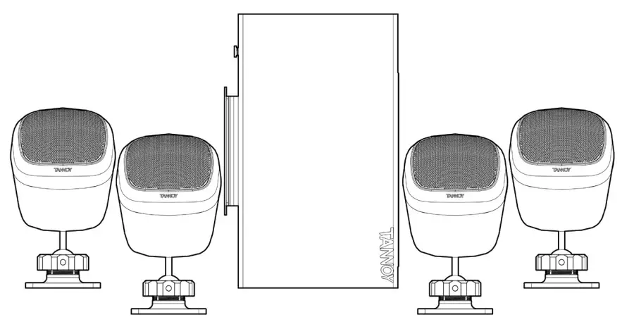
SAT SUB 4 PACK
- Packaged Satellite-Subwoofer Loudspeaker System for Commercial Applications
- Contains four discrete SAT 3 satellite speakers plus one SAT SUB subwoofer loudspeaker system
Unpacking
Every TANNOY product and accessory is carefully inspected before packing. After unpacking, please inspect your product to make sure no damage has occurred in transit. In the unlikely event of any damage, would you please notify your dealer immediately and retain your shipping carton, as your dealer may ask you to return the faulty unit to them for inspection.
Safety Notices
Some regional construction codes require the use of a secondary method of securing loudspeakers to provide the security of backup support. A secondary support line should be attached from the secondary safety screw provided on the rear of the subwoofer, to a strong source point on the wall.Before installing the loudspeaker, please consult the relevant construction codes in your region.When using a power driver to install the product it is essential to use the correct torque level settings to avoid over-tightening and damage to the wall material.TANNOY will not be held responsible for any damages caused by the improper installation of these loudspeakers.
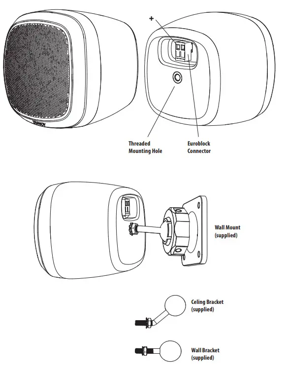
Product Feature Identification
SAT 3
 SAT SUB
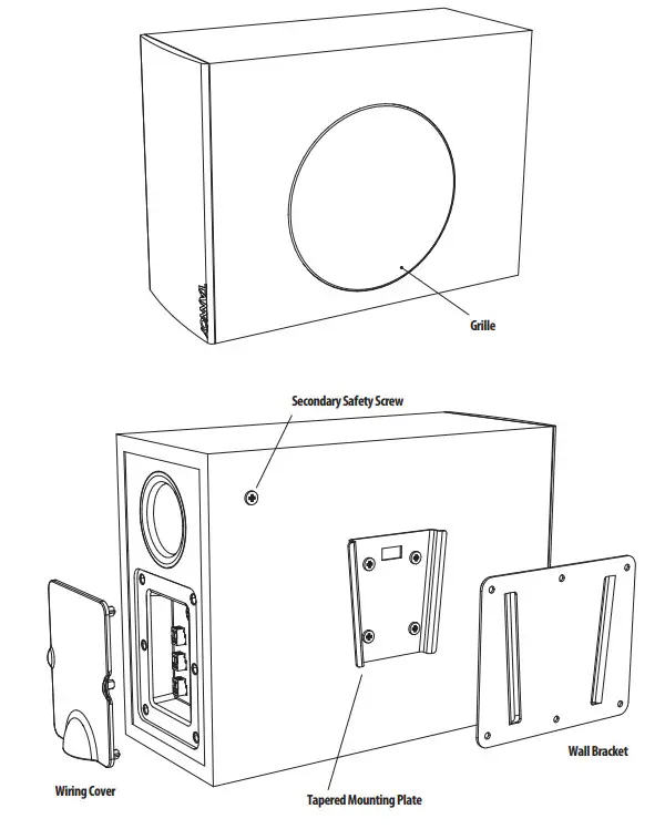
Wiring and Setting Up
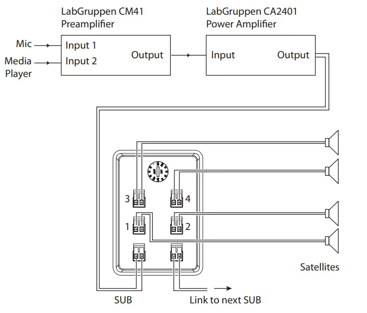
Typical Hookup Diagrams
- Input Sources such as a paging microphone and media player can be connected to a preamplifier such as the LabGruppen CM41. Its line-level output connects to a power amplifier such as the LabGruppen CA2401.
- The speaker level output of the power amplifier connects to the Input connector on the SAT SUB subwoofer.See the next page for details of the connections.
- The SAT 3 satellite speakers connect to the outputs on the SAT SUB subwoofer terminal plate.
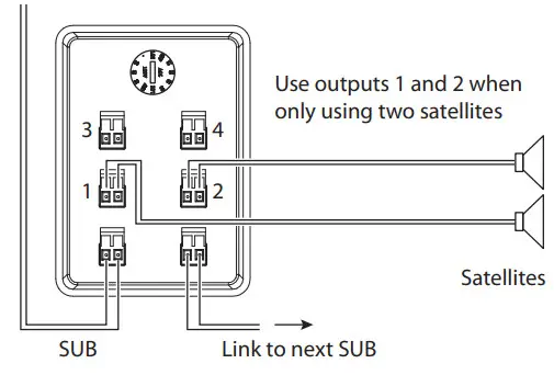
- If only 2 satellites are used, then only connect them to outputs 1 and 2 as shown.
- The link output can be used to connect to the input of another subwoofer.
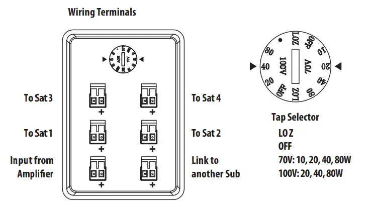
Terminal Connections
- WARNING: To avoid potential damage to your amplifier or loudspeaker, ensure that the amplifier is switched OFF prior to connecting or disconnecting any cables.
- Before switching the amplifier ON, double-check that all connections are secure and that the polarity is correct, and check that the Tap Selector switch on the subwoofer is set correctly to match your power amplifier.
- The speaker wires are attached to the screw terminals of Euroblock connectors, and not to the subwoofer and satellite loudspeakers.
- The mounting brackets of the subwoofer and satellite speakers can be preinstalled and the Euroblock connectors wired up, and the subwoofer and satellite speakers added at a later stage.
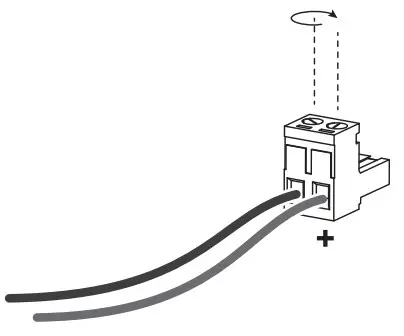
- The two screw terminals of the Euroblock connectors are marked positive (+) and negative (-).
- Strip off approximately 8 mm (1/4″) of the outer protective layer of one conductor and twist its inner cores together to prevent shorting from stray wires. Insert the core into the screw terminal of the Euroblock connector, while ensuring that correct polarity is maintained. Repeat this for both speaker wires. Gently pull on the wires to verify they are making a secure connection.
SAT SUB Subwoofer Installation
- WARNING: To avoid potential damage to your amplifier or loudspeaker, ensure that the amplifier is switched OFF prior to connecting or disconnecting any cables.
- The procedure below describes the installation of the SAT SUB subwoofer into a typical stud wall with drywall/plasterboard.
- Locate a suitable mounting position for the SAT SUB subwoofer within the room, that is practical and will give a good audio performance. You can try connecting and operating the system with the SAT SUB located in various room positions to find the best performance.
- Use a stud-finder to locate a suitable nearby stud and mark this position. WARNING: Make sure that there are no power lines, other cables, or plumbing such as water, sewer, gas lines in the chosen location.
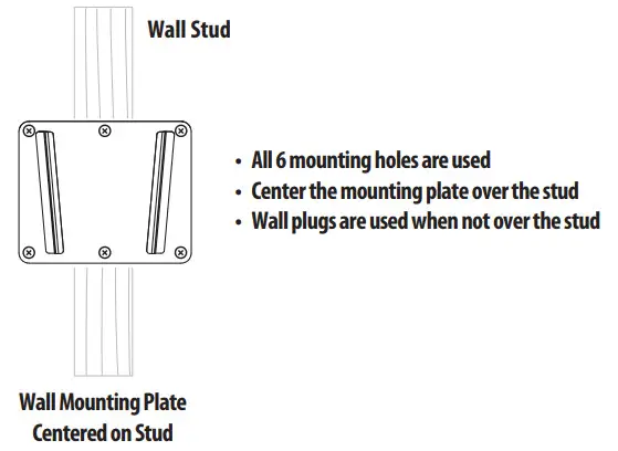
- The SAT SUB mounting bracket should be mounted to a stud. The screws must be long enough to enter into the wood and make a secure and safe mounting position. Make sure that the center top and center bottom mounting holes are used to attach to the stud. Check that the plate is level (and the right way up).
- For the other mounting holes not over a stud, suitable screws and wall plugs must be used to make a secure and safe mounting position. All mounting holes must be used. Consult the relevant construction codes in your region.
- If the mounting bracket is to be mounted to drywall (not over a stud), or on a solid masonary wall, then suitable screws and wall plugs must be used to make a secure and safe mounting position. Consult the relevant construction codes in your region.
- Run the speaker wire from your amplifier to this location, leaving enough slack to allow for the connection.Follow the information on the previous pages to connect the speaker wires from your power amplifier to the Euroblock connector.
- If it will be some time before the SAT SUB subwoofer is installed, cover the mounting bracket and any wiring to prevent any dust, moisture, or paint from entering.
- The SAT SUB subwoofer is provided with an attachment point for a secondary safety cable. This will reduce the chance of the SAT SUB from coming off the wall during an earthquake. Connect up your safety cable to the SAT SUB before mounting it to the wall.
- When ready, carefully align the mounting bracket attached to the SAT SUB subwoofer with the mounting plate on the wall, and lower into position.12. Open the cover to the wiring terminals, and connect the Euroblock connector from the power amplifier. If theSAT 3 satellites are installed, connect their Euroblock connectors as well.
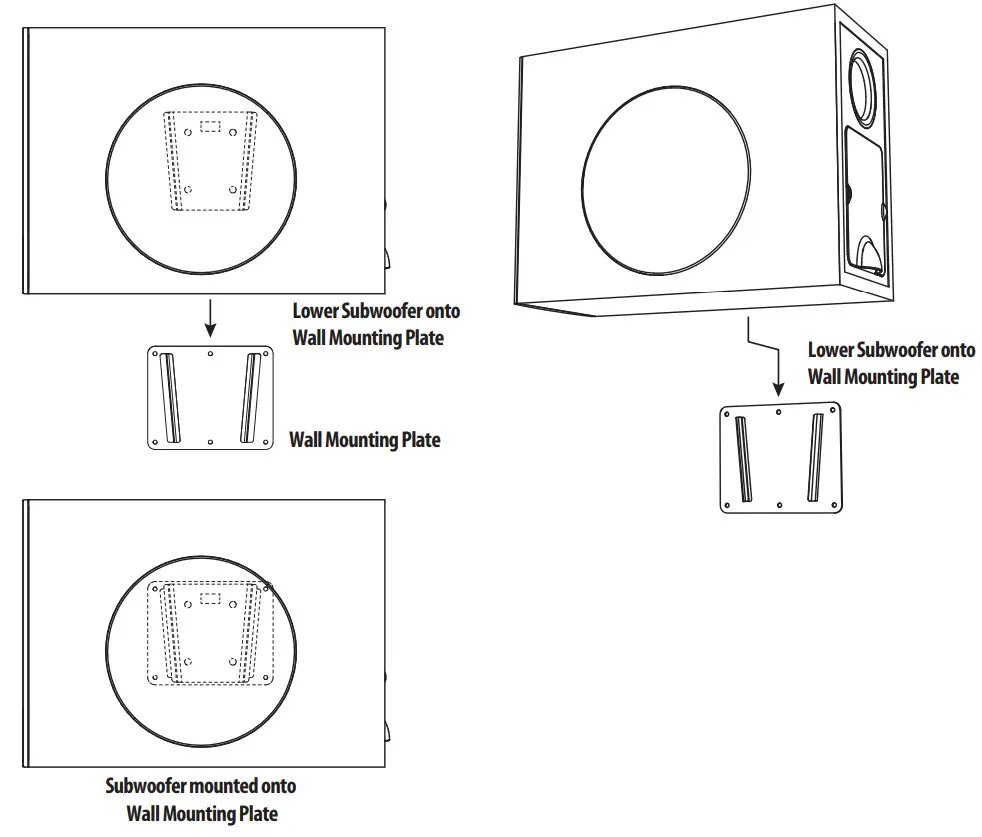 12. Open the cover to the wiring terminals, and connect the Euroblock connector from the power amplifier. If theSAT 3 satellites are installed, connect their Euroblock connectors as well.
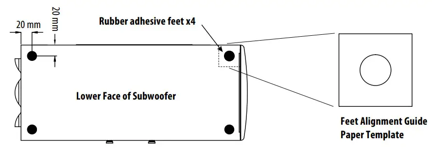
SAT SUB Floor Installation
- Four self-adhesive rubber feet are provided in case the SAT SUB subwoofer is to be used in a standing position, and not mounted to a wall. Press each foot securely in each corner of the bottom, using the supplied paper positioning template as a guide. Make sure the surface is clean and dry before pressing the feet in place.
SAT 3 Satellite Installation
- WARNING: To avoid potential damage to your amplifier or loudspeaker, ensure that the amplifier is switched OFF prior to connecting or disconnecting any cables.
- The procedure below describes the installation of the SAT 3 satellite into a typical wall or ceiling with drywall/plasterboard.
- Locate a suitable mounting position for the SAT 3 satellite within the room, that is practical and will give good audio coverage and performance.
- Use a stud-finder to locate a suitable nearby stud or ceiling joist and mark this position. WARNING: Make sure that there are no power lines, other cables, or plumbing such as water, sewer, gas lines in the chosen location.
- The SAT 3 mounting bracket should be mounted to a wall stud or ceiling joist. The screws must be long enough to enter into the wood and make a secure and safe mounting position. Make sure that at least two mounting holes are used to attach to the stud. Check that the mounting bracket is level.
- For the other mounting holes not over a stud, suitable screws and wall plugs must be used to make a secure and safe mounting position. All mounting holes must be used. Consult the relevant construction codes in your region.
- If the mounting bracket is to be mounted to drywall (not over a stud or joist), or on a solid masonary wall, then suitable screws and wall plugs must be used to make a secure and safe mounting position. Consult the relevant construction codes in your region.
- Run the speaker wire from your SAT SUB subwoofer to this location, leaving enough slack to allow for the connection. Follow the information on the previous pages to connect the speaker wires to the SAT 3 Euroblock connector.
- If it will be some time before the SAT 3 satellite is installed, cover the mounting bracket and any wiring to prevent any dust, moisture, or paint from entering.
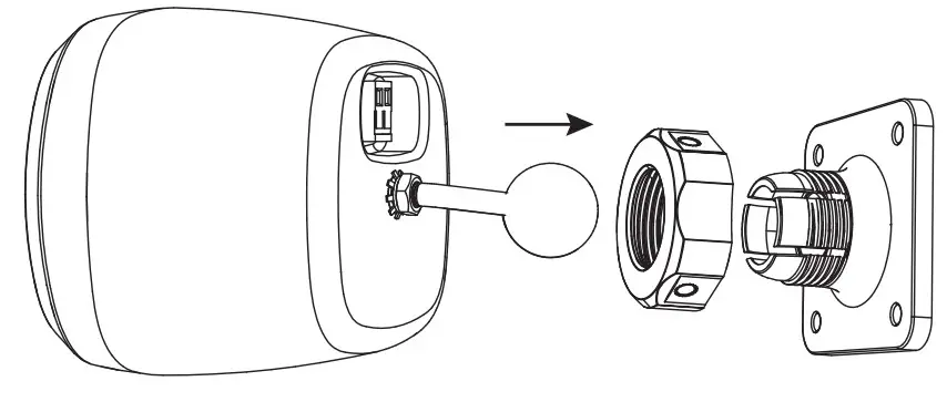
- If the SAT 3 is being mounted to a wall, attach the straight mounting arm to the rear threaded hole, and tighten with a wrench. For ceiling mounting, use the bent mounting arm instead.
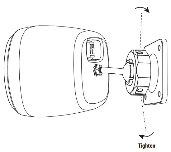
- When the bracket is securely mounted to the wall or ceiling, undo the large nut and press the ball end of the mounting arm into the bracket. Press the arm firmly in place, and tighten the nut to secure the SAT 3 at the desired angle.
- Tighten the nut securely by using a small screwdriver or bar in any of the three holes in the circumference of the nut. (The hole diameter is 4.7 mm [0.185 inches].)
System Testing
- Check the wiring from the power amplifier to the SAT SUB subwoofer.
- Check the wiring from the SAT SUB subwoofer to the SAT 3 satellites.
- Check that the SAT SUB subwoofer Tap Selector is set correctly for your power amplifier and your system design.
- Turn on the preamplifier first, and turn down the system volume.
- Turn on the power amplifier.
- Play your source material and adjust the volume slowly to the desired level.
- Check that each loudspeaker is playing correctly.
- In general use, turn on the preamplifier first, before the power amplifier, and when shutting down, turn off the power amplfier first, before the preamplifier. This will reduce the chance of turn-on and turn-off “thumps” being heard in your system.
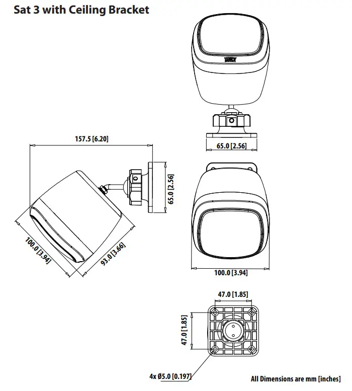
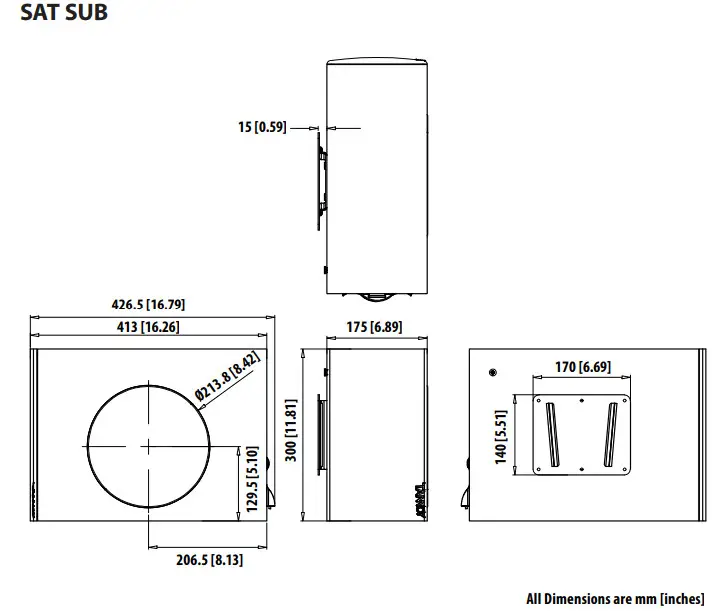
Dimensions
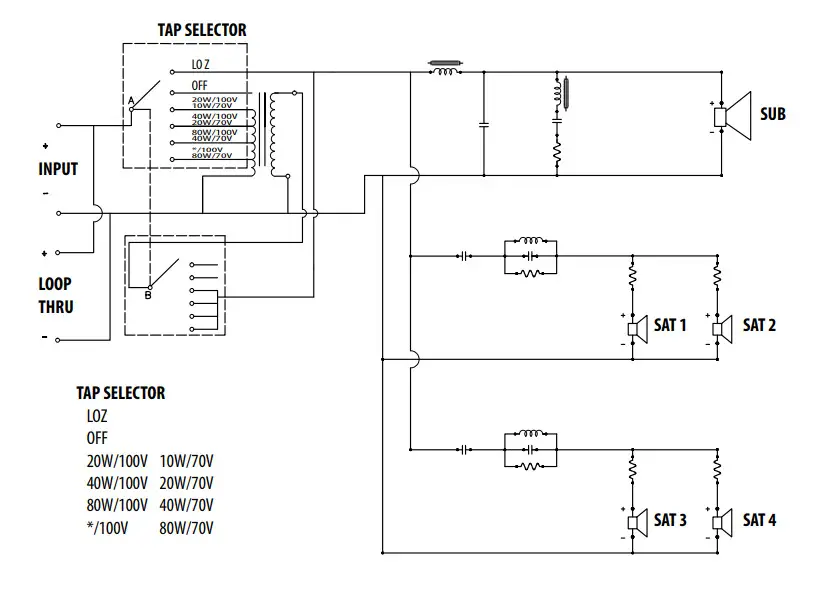
Block Diagram
Specifications
| SAT 3 | SAT SUB | |
| Performance | ||
| Frequency response (-10 dB) 200 Hz —20 kHz 32 Hz — 260Hz | 200 Hz –20 kHz | 32 Hz – 260Hz |
| Sensitivity 1 W/ 1m 83 dB 93 dB | 83 dB | 93 dB |
| Power handling | ||
| Average | 15W | 80 W |
| Programme | 25W | 120 W |
| Recommended amplifier power | 25 W @ 16 0 | 120 D |
| Nominal Impedance | 164 | 84 |
| Maximum SPL @1 m | 100 dB | 116 dB |
| Transformer taps | NA | 100V: 20, 40, 80, 8 LoZ, 70V: 10, 20, 40, 80, 8 LoZ |
| Crossover point | NA | 200 Hz |
| Coverage angle @ 1 kHz | 265° horizontal, 265° vertical | |
| Transducers | ||
| Diameter/material/type | 63.5mm (2.5″) Paper | 1 x 165 mm (6.5″) Paper |
| Physical | ||
| Enclosure material | ABS | MDF |
| Grille material | Steel | Steel |
| Connectors | Phoenix Contact terminal block | Phoenix Contact terminal block x 6 |
| Dimensions (HxWxD) | 100 x 100 x 93 mm (speaker only,no bracket included) | 175 x 413 x 300 mm(speaker only, no bracket included) |
| Net weight | 1.16 kg (2.6 Ibs) (bracket included) | 10.7 kg 23.5 Ibs) (bracket included) |
| Included accessories | Ceiling mount bracket, wall mount bracket | wall mount bracket, 4x rubber feet, and paper positioning template |
Other important information
- Register online.Please register your new Music Tribe equipment right after you purchase it byvisiting musictribe.com. Registering yourpurchase using our simple online form helps us to process your repair claims more quickly and efficiently. Also, read the terms and conditions of our warranty, if applicable.
- Malfunction.Should your Music Tribe Authorized Reseller not be located in your vicinity, you may contact the Music Tribe Authorized Fulfiller for your country listed under “Support” at musictribe.com. Should your country not be listed, please check if your problem can be dealt with by our “Online Support”which may also be found under “Support”at musictribe.com. Alternatively, please submit an online warranty claim at musictribe.com BEFORE returning the product.
 report this ad
![]()
References
[xyz-ips snippet=”download-snippet”]