![]() Quick Start Guide
Quick Start Guide
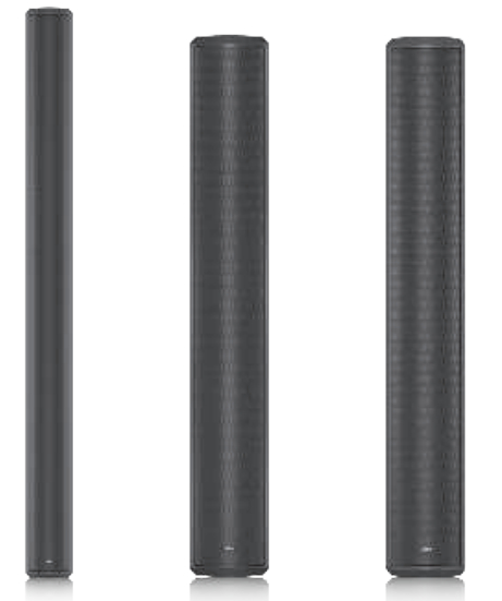
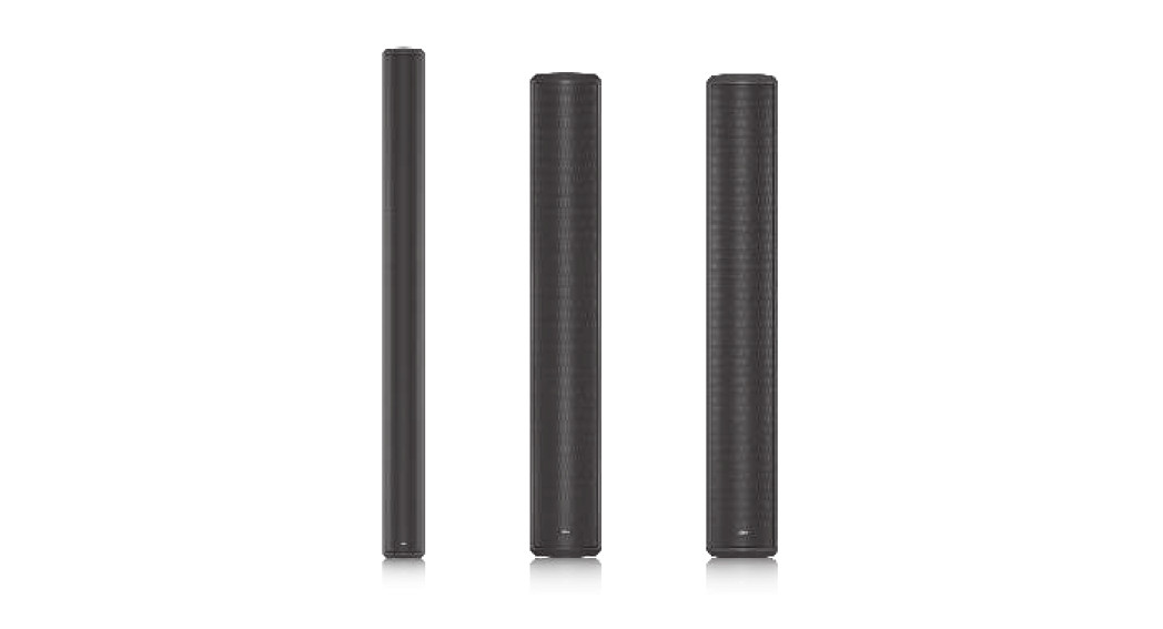
VLS SERIESVLS 30Passive Column Array Loudspeaker with 30 Drivers and FAST Dispersion Control for Installation ApplicationsVLS 15 (EN 54)Passive Column Array Loudspeaker with 15 Drivers and FAST Dispersion Control for Installation Applications (EN 54-24 Certified)VLS 7 (EN 54)Passive Column Array Loudspeaker with 7 Full-Range Drivers and FAST Dispersion Control for Installation Applications (EN 54-24 Certified)
Important Safety Instructions
![]() CAUTION: RISK OF ELECTRIC SHOCK! DO NOT OPEN!
CAUTION: RISK OF ELECTRIC SHOCK! DO NOT OPEN!![]()
![]() Terminals marked with this symbol carry an electrical current of sufficient magnitude to constitute a risk of electric shock. Use only high-quality professional speaker cables with ¼” TS or twist-locking plugs pre-installed. All other installation or modifications should be performed only by qualified personnel.
Terminals marked with this symbol carry an electrical current of sufficient magnitude to constitute a risk of electric shock. Use only high-quality professional speaker cables with ¼” TS or twist-locking plugs pre-installed. All other installation or modifications should be performed only by qualified personnel.
![]() This symbol, wherever it appears, alerts you to the presence of uninsulated dangerous voltage inside the enclosure – voltage that may be sufficient to constitute a risk of shock.
This symbol, wherever it appears, alerts you to the presence of uninsulated dangerous voltage inside the enclosure – voltage that may be sufficient to constitute a risk of shock.
![]() This symbol, wherever it appears, alerts you to important operating and maintenance instructions in the accompanying literature. Please read the manual.
This symbol, wherever it appears, alerts you to important operating and maintenance instructions in the accompanying literature. Please read the manual.
![]() CautionTo reduce the risk of electric shock, do not remove the top cover (or the rear section). No user-serviceable parts inside. Refer servicing to qualified personnel.
CautionTo reduce the risk of electric shock, do not remove the top cover (or the rear section). No user-serviceable parts inside. Refer servicing to qualified personnel.
![]() CautionTo reduce the risk of fire or electric shock, do not expose this appliance to rain and moisture. The apparatus shall not be exposed to dripping or splashing liquids and no objects filled with liquids, such as vases, shall be placed on the apparatus.
CautionTo reduce the risk of fire or electric shock, do not expose this appliance to rain and moisture. The apparatus shall not be exposed to dripping or splashing liquids and no objects filled with liquids, such as vases, shall be placed on the apparatus.
![]() CautionThese service instructions are for use by qualified service personnel only. To reduce the risk of electric shock do not perform any servicing other than that contained in the operation instructions. Repairs have to be performed by qualified service personnel.
CautionThese service instructions are for use by qualified service personnel only. To reduce the risk of electric shock do not perform any servicing other than that contained in the operation instructions. Repairs have to be performed by qualified service personnel.
- Read these instructions.
- Keep these instructions.
- Heed all warnings.
- Follow all instructions.
- Do not use this apparatus near water.
- Clean only with a dry cloth.
- Do not block any ventilation openings. Install in accordance with the manufacturer’s instructions.
- Do not install near any heat sources such as radiators, heat registers, stoves, or other apparatus (including amplifiers) that produce heat.
- Do not defeat the safety purpose of the polarized or grounding-type plug. A polarized plug has two blades with one wider than the other. A grounding-type plug has two blades and a third grounding prong. The wide blade or the third prong is provided for your safety. If the provided plug does not fit into your outlet, consult an electrician for the replacement of the obsolete outlet.
- Protect the power cord from being walked on or pinched particularly at plugs, convenience receptacles, and the point where they exit from the apparatus.
- Use only attachments/accessories specified by the manufacturer.

- Use only with the cart, stand, tripod, bracket, or table specified by the manufacturer, or sold with the apparatus. When a cart is used, use caution when moving the cart/apparatus combination to avoid injury from tip-over.
- Unplug this apparatus during lightning storms or when unused for long periods of time.
- Refer all servicing to qualified service personnel. Servicing is required when the apparatus has been damaged in any way, such as power supply cord or plug is damaged, liquid has been spilled or objects have fallen into the apparatus, the apparatus has been exposed to rain or moisture, does not operate normally, or has been dropped.
- The apparatus shall be connected to a MAINS socket outlet with a protective earthing connection.
- Where the MAINS plug or an appliance coupler is used as the disconnect device, the disconnect device shall remain readily operable.
- Correct disposal of this product: This symbol indicates that this product must not be disposed of with household waste, according to the WEEE Directive (2012/19/EU) and your national law. This product should be taken to a collection center licensed for the recycling of waste electrical nd electronic equipment (EEE). The mishandling of this type of waste could have a possible negative impact on the environment and human health due to potentially hazardous substances that are generally associated with EEE. At the same time, your cooperation in the correct disposal of this product will contribute to the efficient use of natural resources. For more information about where you can take your waste equipment for recycling, please contact your local city office or your household waste collection service.
- Do not install in a confined space, such as a bookcase or similar unit.
- Do not place naked flame sources, such as lighted candles, on the apparatus.
- Please keep the environmental aspects of battery disposal in mind. Batteries must be disposed of at a battery collection point.
- This apparatus may be used in tropical and moderate climates up to 45°C.

LEGAL DISCLAIMERMusic Tribe accepts no liability for any loss which may be suffered by any person who relies either wholly on or in part upon any description, photograph, or statement contained herein. Technical specifications, appearances, and other information are subject to change without notice. All trademarks are the property of their respective owners. Midas, Klark Teknik, Lab Gruppen, Lake, Tannoy, Turbosound, TC Electronic, TC Helicon, Behringer, Bugera, Oberheim, Auratone, Aston Microphones, and Coolaudio are trademarks or registered trademarks of Music Tribe Global Brands Ltd. © Music Tribe Global Brands Ltd. 2021 All rights reserved.
LIMITED WARRANTYFor the applicable warranty terms and conditions and additional information regarding Music Tribe’s Limited Warranty, please see complete details online amusictribe.com/warranty
Introduction
The latest addition to Tannoy’s extensive line of column loudspeakers, VLS Series introduces another proprietary Tannoy innovation:FAST (Focussed Asymmetrical Shaping Technology). By combining transducer technology from the acclaimed QFlex Series with an innovative new passive crossover design, FAST provides exceptional acoustical benefits, including an asymmetrical vertical dispersion pattern that gently shapes acoustical coverage toward the lower quadrant of the vertical axis. The VLS 7 and 15 are EN54-24 certified for use in fire detection and fire alarm systems.This Quick Start Guide presents only the essential information required to properly unpack, connect and configure a VLS Series loudspeaker. Please consult the full VLS Series Operation Manual for additional detailed information on low impedance versus 70/100 V operation, complex loudspeaker system configuration, cable types, equalization, power handling, rigging and safety procedures, and warranty coverage.
Unpacking
Each Tannoy VLS Series loudspeaker is carefully tested and inspected prior to shipment. After unpacking, please inspect for any exterior physical damage, and save the carton and any relevant packaging materials in case the loudspeaker again requires packing and shipping. In the event that damage has been sustained in transit, please notify your dealer and the shipping carrier immediately.
Connectors and cabling
VLS Series loudspeakers are connected to the amplifier (or to other loudspeakers in a 70/100 V system or series/parallel configuration) using a pair of internally paralleled barrier strip connectors.All VLS Series models can be operated as either a low impedance loudspeaker or within a 70/100 V distributed system. The operation mode is selectable via a single switch located on the rear of the cabinet (see below).
Operation in low impedance mode often will require the use of larger diameter cables than are needed for a 70/100 V distributed system. Please consult the full VLS Operation Manual for recommended cable types for various applications.
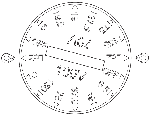
Switch for Low-Z and transformer tap selection
A multi-position rotary switch on the rear input panel selects either the low-impedance operating mode or the high-impedance modes (70 V or 100 V) with available transformer taps. When using VLS Series loudspeakers in distributed line systems, the transformer can be tapped with available power levels shown in the table below:
| 70 V | 100 V |
| 5 W | 9.5 W |
| 9.5 W | 19 W |
| 19 W | 37.5 W |
| 37.5 W | 75 W |
| 75 W | 150 W |
| 150 W | — |
All transformer primaries should be connected in parallel to the output of the amplifier. The summed total power rating in watts of the selected tap settings for all connected loudspeakers must not exceed the total output power rating of the connected amplifier output channel in watts. It is recommended that a generous power safety margin (minimum 3 dB headroom) be maintained between the total loudspeaker power requirements and the amplifier output capacity to avoid continuous amplifier operation at full rated output.
Wiring the connectors
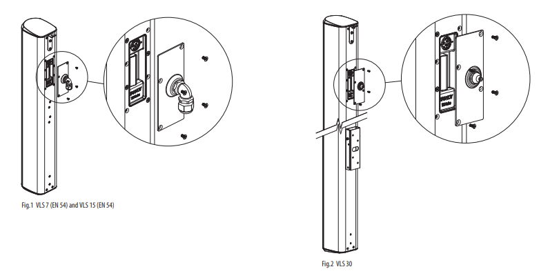
Low Impedance (8 ohms) ModeIf connecting directly to the amplifier in low impedance mode, connect the positive (+) conductor to a positive (+) barrier strip terminal and the negative (–) conductor to a negative (–) terminal. It is preferable to connect several loudspeakers to one amplifier output in parallel, series, or series/parallel configurations using the other internally paralleled barrier strip connector.For more information on this, please consult the full VLS Series, Operation Manual.Constant voltage (70 V / 100 V) ModeIn constant voltage distributed systems, normally a number of loudspeakers are connected in parallel to the single amplifier output. Connect the positive (+) conductor from the amplifier or prior loudspeaker in the system to a positive (+) barrier strip terminal and the negative (–) conductor to a negative (–) terminal. The other parallel barrier strip is available for connecting additional loudspeakers.Outdoor ApplicationsA right-angled water-tight cable gland is supplied with the VLS 7 (EN 54) and VLS 15 (EN 54) for use in outdoor applications (Fig.1). The VLS 30 has an input panel cover with a rubber wiring grommet for use in outdoor applications (Fig.2). Before making connections, pass the wire(s) through the cable grand/rubber grommet. The input panel cover is secured to the cabinet using the four screws already inserted around the input.
Asymmetric vertical pattern: mounting and flyingVLS Series loudspeakers are designed with an asymmetrical vertical dispersion pattern, a feature that allows improved performance with simplified mounting in many applications. The vertical dispersion of the VLS 7 (EN 54) and VLS 15 (EN 54) models is +6/-22 degrees from the center axis, while the pattern of the VLS 30 is +3/-11 degrees from the center axis.Please be aware of this feature when planning your installation. In many situations where conventional column loudspeakers ould require substantial downward tilt, a VLS Series loudspeaker would require less tilt or even allow flush mounting, thus providing a simpler installation with improved visual aesthetics.
Mounting and fixing
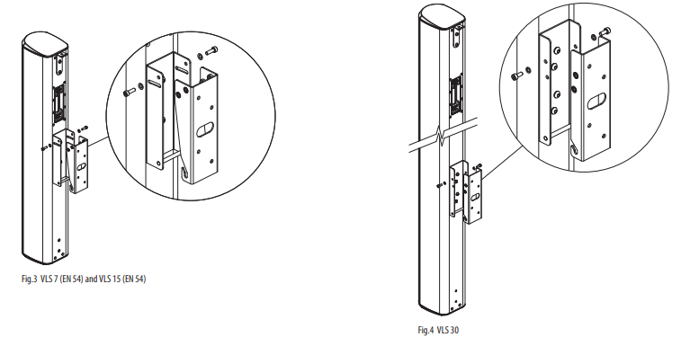
Wall BracketEach VLS Series loudspeaker is supplied with a standard wall bracket suitable for mounting on most wall surfaces. The bracket is supplied as two interlocking U plates. One plate attaches to the rear of the loudspeaker with four supplied screws. The other part is secured to the wall. The bar on the bottom of the speaker plate slides into the bottom notch of the wall plate, while the top is secured with the two supplied screws. The bracket for the VLS 7 (EN 54) and VLS 15 (EN 54) is slotted to allow an angle between 0 and 6 degrees (Fig.3). Aligning the top two screw holes of the VLS 30 results in a flat flush mount; using the lower two screw positions provides a 4 degree downward tilt. (Fig.4)
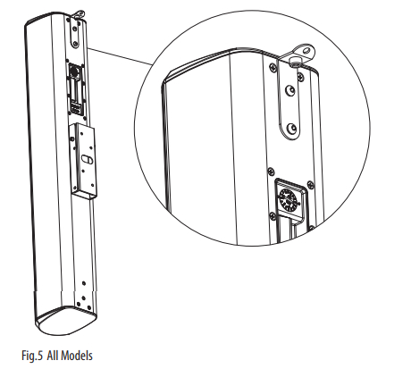
Flying BracketEach VLS Series loudspeaker is also supplied with a flying bracket. The bracket is attached to the top two inserts using the supplied M6 screws (Fig.5). The two bottom inserts can be used as pull back if required.
Pan-Tilt Bracket (optional)A pan-tilt bracket is available which allows panning and tilting for flexible orientation along both horizontal and vertical axes. Installation instructions are provided with the bracket.
Rigging and safety proceduresThe installation of Tannoy loudspeakers using the dedicated hardware should be carried out only by fully qualified installers, in accordance with all the required safety codes and standards that are applied at the place of installation.
WARNING: As the legal requirements for flying vary from country to country, please consult your local safety standards office before installing any product. We also recommend that you thoroughly check any laws and bylaws prior to installation. For more detailed information on rigging hardware and safety procedures, please consult the full VLS Series, Operation Manual.
Outdoor applicationsVLS Series loudspeakers are rated IP64 for resistance to dust and moisture ingress, and are resistant to both salt spray and UV exposure, making them suitable for use in most outdoor applications. Please consult with your Tannoy dealer before installation in applications with extreme exposure to adverse environmental conditions such as prolonged heavy rainfall, prolonged temperature extremes, etc.
IMPORTANT NOTE: The mounting of a permanently installed sound system may be dangerous unless undertaken by qualified personnel with the required experience and certification to perform the necessary tasks. Walls, floors or ceilings must be capable of safely and securely supporting the actual load. The mounting accessory used must be safely and securely fixed both to the loudspeaker and to the wall, floor or ceiling.
When mounting rigging components on walls, floors, or ceilings, ensure that all fixings and fasteners used are of an appropriate size and load rating. Wall and ceiling claddings, and the construction and composition of walls and ceilings, all need to be taken into account when determining whether a particular fixing arrangement can be safely employed for a particular load. Cavity plugs or other specialist fixings, if required, must be of an appropriate type, and must be fitted and used in accordance with the maker’s instructions.
The operation of your speaker cabinet as part of a flown system, if installed incorrectly and improperly, can potentially expose persons to serious health risks and even death. In addition, please ensure that electrical, mechanical, and acoustic considerations are discussed with qualified and certified (by local state or national authorities) personnel prior to any installation or flying.
Make sure that speaker cabinets are set up and flown by qualified and certified personnel only, using dedicated equipment and original parts and components delivered with the unit. If any parts or components are missing please contact your Dealer before attempting to set up the system.
Be sure to observe the local, state, and other safety regulations applicable in your country. Music Tribe, including the Music Tribe companies listed on the enclosed “Service Information Sheet”, assumes no liability for any damage or personal injury resulting from improper use, installation or operation of the product. Regular checks must be conducted by qualified personnel to ensure that the system remains in a secure and stable condition. Make sure that, where the speaker is flown, the area underneath the speaker is free of human traffic. Do not fly the speaker in areas that can be entered or used by members of the public.
Speakers create a magnetic field, even if not in operation. Therefore, please keep all materials that can be affected by such fields (discs, computers, monitors, etc) at a safe distance. A safe distance is usually between 1 and 2 meters.
Technical Specifications
System VLS 7 (EN 54) / VLS 7 (EN 54)-WH VLS 15 (EN 54) / VLS 15 (EN 54)-WH VLS 30 / VLS 30 -WH
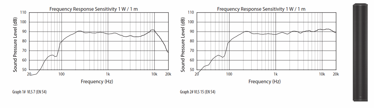
| Frequency response | see Graph 1# as below | see Graph 2# as below | 120 Hz – 22 kHz ±3 dB90 Hz – 35 kHz -10 dB |
| Horizontal dispersion (-6 dB) | 130° H | ||
| Vertical dispersion (-6 dB) | +6° / -22° V (-8° bias) | +6° / -22° V (-8° bias) | +3° / -11° V (-4° bias) |
| Power handling (IEC) | 150 W average, 300 W continuous, 600 W peak | 200 W average, 400 W continuous, 800 W peak | 400 W average, 800 W continuous, 1600 W peak |
| Recommended amplifier power | 450 W @ 8 Ω | 600 W @ 8 Ω | 1200 W @ 4 Ω |
| System sensitivity | 90 dB (1 m, Lo Z) | 91 dB (1 m, Lo Z) | 94 dB (1 m, Lo Z) |
| Sensitivity (per EN54-24) | 76 dB (4 M, through transformer) | — | |
| Nominal impedance (Lo Z) | 12 Ω | 6 Ω | |
| Maximum SPL (per EN54-24) | 91 dB (4 M, through transformer) | 96 dB (4 M, through transformer) | — |
| Rated maximum SPL | 112 dB continuous, 118 dB peak (1 m, Lo Z) | 114 dB continuous, 120 dB peak (1 m, Lo Z) | 120 dB continuous, 126 dB peak (1 m, Lo Z) |
| Crossover | Passive, utilizing Focussed Asymmetrical Shaping Technology (FAST) | ||
| Crossover point | — | 2.5 kHz | |
| Directivity factor (Q) | 6.1 averaged, 1 kHz to 10 kHz | 9.1 averaged, 1 kHz to 10 kHz | 15 averaged, 1 kHz to 10 kHz |
| Directivity index (DI) | 7.9 averaged, 1 kHz to 10 kHz | 9.6 average, 1 kHz to 10 kHz | 11.8 average, 1 kHz to 10 kHz |
| Components | 7 x 3.5″ (89 mm) fullrange drivers | 7 x 3.5″ (89 mm) woofers 8 x 1″ (25 mm) metal dome tweeters | 14 x 3.5″ (89 mm) woofers 16 x 1″ (25 mm) metal dome tweeters |
Transformer taps (via rotary switch) (Rated noise power and impedance)
|
70 V |
150 W (33 Ω) / 75 W (66 Ω) / 37.5 W (133 Ω) / 19 W (265 Ω) / 9.5 W (520 Ω) / 5 W (1000 Ω) | 150 W / 75 W / 37.5 W / 19 W / 9.5 W / |
| OFF & low impedance operation | 5 W / OFF & low impedance operation | |
|
100 V |
150 W (66 Ω) / 75 W (133 Ω) / 37.5 W (265 Ω) / 19 W (520 Ω) / 9.5 W (1000 Ω) / | 150 W / 75 W / 37.5 W / 19 W / 9.5 W / |
| OFF & low impedance operation | OFF & low impedance operation |
Coverage angles
| 500 Hz | 360° H x 129° V | 226° H x 114° V | 220° H x 41° V |
| 1 kHz | 202° H x 62° V | 191° H x 57° V | 200° H x 21° V |
| 2 kHz | 137° H x 49° V | 131° H x 32° V | 120° H x 17° V |
| 4 kHz | 127° H x 40° V | 119° H x 27° V | 120° H x 20° V |
Enclosure
| Connectors | Barrier strip | ||
| Wiring | Terminal 1+ / 2- (input); 3- / 4+ (link) | ||
| Dimensions H x W x D | 816 x 121 x 147 mm (32.1 x 4.8 x 5.8″) | 1461 x 121 x 147 mm (57.5 x 4.8 x 5.8″) | |
| Net weight | 10.8 kg (23.8 lbs) | 11.7 kg (25.7 lbs) | 19 kg (41.8 lbs) |
| Construction | Aluminum extrusion | ||
| Finish | Paint RAL 9003 (white) / RAL 9004 (black) Custom RAL colours available (additional cost and lead-time) | ||
| Grille | Powder-coated perforated steel | ||
| Flying hardware | Flying bracket, wall mount bracket, input panel cover plate, and gland |
Flying bracket, wall mount bracket, input panel cover plate and gland
Notes:
- Average over-stated bandwidth. Measured in an IEC baffle in an Anechoic Chamber
- Unweighted pink noise input, measured at 1 meter on axis
- Long term power handling capacity as defined in the IEC268-5 test
- The reference point for the reference axis (on-axis) is the center of the baffle
Other important information
Important information
- Register online. Please register your new Music Tribe equipment right after you purchase it by visiting musictribe.com. Registering your purchase using our simple online form helps us to process your repair claims more quickly and efficiently. Also, read the terms and conditions of our warranty, if applicable.
- Malfunction. Should your Music Tribe Authorized Reseller not be located in your vicinity, you may contact the Music Tribe Authorized Fulfiller for your country listed under “Support” at musictribe.com. Should your country not be listed, please check if your problem can be dealt with by our “Online Support” which may also be found under “Support” at musictribe.com. Alternatively, please submit an online warranty claim at musictribe.com BEFORE returning the product.
- Power Connections. Before plugging the unit into a power socket, please make sure you are using the correct mains voltage for your particular model. Faulty fuses must be replaced with fuses of the same type and rating without exception.
![]()
Hereby, Music Tribe declares that this product is in compliance with Directive2011/65/EU and Amendment 2015/863/EU, Directive 2012/19/EU, Regulation519/2012 REACH SVHC and Directive 1907/2006/EC, and this passive product is notapplicable to EMC Directive 2014/30/EU, LV Directive 2014/35/EU.Full text of EU DoC is available at https://community.musictribe.com/EU Representative: Music Tribe Brands DK A/SAddress: Ib Spang Olsens Gade 17, DK – 8200 Aarhus N, Denmark
References
[xyz-ips snippet=”download-snippet”]