
![]()
Quick Start Guide
VQ 100/VQ 603 Way Dual 12″ Large Format Loudspeaker for High-Performance Installation ApplicationsVQ 85DF/VQ 64DF2 Way Down-Firing Dual Concentric Mid-High Loudspeaker for High-Performance Installation ApplicationsVQ 64MH2 Way Dual Concentric Mid-High Large Format Loudspeaker for High-Performance Installation ApplicationsVQ MBDual 12″ Mid-Bass Large Format Loudspeaker for High-Performance Installation Applications
Important safety instructions
| CAUTIONRISK OF ELECTRIC SHOCKDO NOT OPENATTENTIONRISQEUE ELECTROCUTIONNE PASOUVRIR |  |
![]() Terminals marked with this symbol carry an electrical current of sufficient magnitude to constitute a risk of electric shock. Use only high-quality professional speaker cables with¼” TS or twist-locking plugs pre-installed. All other installation or modifications should be performed only by qualified personnel.
Terminals marked with this symbol carry an electrical current of sufficient magnitude to constitute a risk of electric shock. Use only high-quality professional speaker cables with¼” TS or twist-locking plugs pre-installed. All other installation or modifications should be performed only by qualified personnel.
![]() This symbol, wherever it appears, alerts you to the presence of uninsulated dangerous voltage inside the enclosure – voltage that may be sufficient to constitute a risk of shock.
This symbol, wherever it appears, alerts you to the presence of uninsulated dangerous voltage inside the enclosure – voltage that may be sufficient to constitute a risk of shock.
This symbol, wherever it appears, alerts you to important operating and maintenance instructions in the accompanying literature. Please read the manual.
Caution To reduce the risk of electric shock, do not remove the top cover (or the rear section). No user-serviceable parts inside. Refer servicing to qualified personnel.
Caution To reduce the risk of fire or electric shock, do not expose this appliance to rain and moisture. The apparatus shall not be exposed to dripping or splashing liquids and no objects filled with liquids, such as vases, shall be placed on the apparatus.
Caution These service instructions are for use by qualified service personnel only. To reduce the risk of electric shock do not perform any servicing other than that contained in the operation instructions. Repairs have to be performed by qualified service personnel.
- Read these instructions.
- Keep these instructions.
- Heed all warnings.
- Follow all instructions.
- Do not use this apparatus near water.
- Clean only with a dry cloth.
- Do not block any ventilation openings. Install in accordance with the manufacturer’s instructions.
- Do not install near any heat sources such as radiators, heat registers, stoves, or other apparatus(including amplifiers) that produce heat.
- Do not defeat the safety purpose of the polarized or grounding-type plug. A polarized plug has two blades with one wider than the other. A grounding-type plug has two blades and a third grounding prong. The wide blade or the third prong is provided for your safety. If the provided plug does not fit into your outlet, consult an electrician for the replacement of the obsolete outlet.
- Protect the power cord from being walked on or pinched particularly at plugs, convenience receptacles, and the point where they exit from the apparatus.
- Use only attachments/accessories specified by the manufacturer.

- Use only with the cart, stand, tripod, bracket, or table specified by the manufacturer, or sold with the apparatus. When a cart is used, use caution when moving the cart/apparatus combination to avoid injury from tip-over
- Unplug this apparatus during lightning storms or when unused for long periods of time.
- Refer all servicing to qualified service personnel. Servicing is required when the apparatus has been damaged in any way, such as power supply cord or plug is damaged, liquid has been spilled or objects have fallen into the apparatus, the apparatus has been exposed to rain or moisture, does not operate normally, or has been dropped.
- The apparatus shall be connected to a MAINS socket outlet with a protective earthing connection.
- Where the MAINS plug or an appliance coupler is used as the disconnect device, the disconnect device shall remain readily operable.
- Correct disposal of this product: This symbol indicates that this product must not be disposed of with household waste, according to the WEEE Directive (2012/19/EU) and your national law. This product should be taken to a collection center licensed for the recycling of waste electrical and electronic equipment (EEE). The mishandling of this type of waste could havea possible negative impact on the environment and human health due to potentially hazardous substances that are generally associated with EEE. At the same time, your cooperation in the correct disposal of this product will contribute to the efficient use of natural resources. For more information about where you can take your waste equipment for recycling, please contact your local city office or your household waste collection service.
- Do not install in a confined space, such as a bookcase or similar unit.
- Do not place naked flame sources, such as lighted candles, on the apparatus.
- Please keep the environmental aspects of battery disposal in mind. Batteries must be disposed of at a battery collection point.
- This apparatus may be used in tropical and moderate climates up to 45°C.

 Correct disposal of this product: This symbol indicates that this product must not be disposed of with household waste, according to the WEEE Directive (2012/19/EU) and your national law. This product should be taken to a collection center licensed for the recycling of waste electrical and electronic equipment (EEE). The mishandling of this type of waste could havea possible negative impact on the environment and human health due to potentially hazardous substances that are generally associated with EEE. At the same time, your cooperation in the correct disposal of this product will contribute to the efficient use of natural resources. For more information about where you can take your waste equipment for recycling, please contact your local city office or your household waste collection service.
LEGAL DISCLAIMER
Music Tribe accepts no liability for any loss which may be suffered by any person who relies either wholly on or in part upon any description, photograph, or statement contained herein. Technical specifications, appearances, and other information are subject to change without notice. All trademarks are the property of their respective owners. Midas, Klark Teknik, Lab Gruppen, Lake, Tannoy, Turbosound, TC Electronic, TC Helicon, Behringer, Bugera, Auratone, and Coolaudio are trademarks or registered trademarks of Music Tribe Global Brands Ltd. © Music Tribe Global Brands Ltd. 2020 All rights reserved.
LIMITED WARRANTY
For the applicable warranty terms and conditions and additional information regarding Music Tribe’sLimited Warranty, please see complete details online atmusictribe.com/warranty.
IntroductionThe VQ full range products utilize a unique driver technology to radiate a coherent single point source for superior dispersion control when coupled to our single horn.This advanced design aligns the acoustical centers of the transducers providing a single coherent wavefront emanating from the throat. The driver uses two concentric annular ring diaphragms. The larger of the two has a 3.5” voice coil and reproduces frequencies from 400 Hz to 7 kHz. Another major advantage here is that there is no crossover anywhere near the vocal region ensuring the most natural and phase-coherent reproduction at this critical area. The 2” HF diaphragm takes over at 7 kHz to 22 kHz by way of a passive or an active crossover. The external casting features extensive heatsinking ensuring good heat transfer for high power handling and very low power compression.
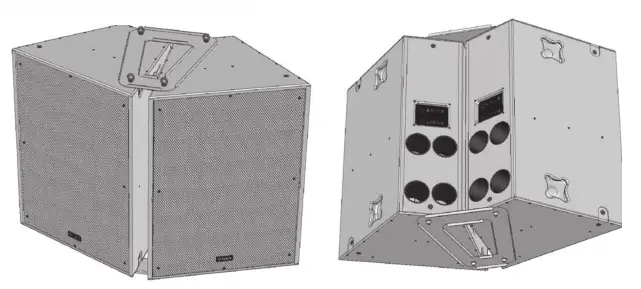
Connectors/Cabling
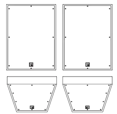
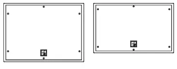
Input Connector PanelsNote: The VQ 60 and VQ 100 are configured as standard for Bi-Amp operation.Tri-Amp operation is possible using the Barrier strip input terminals.The VQ DF is configured as standard for single amp operation. Bi-Amp operation is possible using the Barrier strip input terminals.The VQ MB is configured for single amp operation.
 VQ MB
VQ MB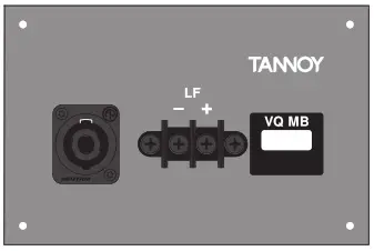
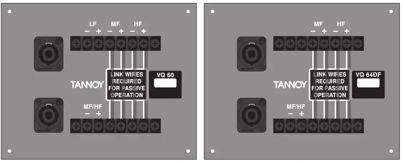
The VQ 60, VQ 100, and VQ DF are fitted with 4-pole Neutrik Speakon connectors and barrier strip for fixed installations.Speakon Connections-Speakon has the following advantages over EP and XLR type connectors:All terminations are solderless; this makes life easier at the time of installation or when field servicing is required. Contacts will accept 6 sq. mm wire with an outside diameter of up to 15 mm and a current rating of 30 Amps. The pins of the 2 Speakon sockets identified input/output on the rear of the input panel are paralleled within the enclosure to facilitate the connection to additional VQ loudspeakers (except the VQ MB). Tannoy has adopted the standard professional audio wiring convention for the VQ product.
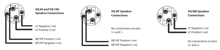
Barrier Strip ConnectionsThe barrier strip accommodates bare wire, tinned leads, or spade connectors. The barrier strips are specifically designed for utilization in fixed/permanent installations. The VQ 60 and VQ 100 are configured for Bi-amp operation; by removing the 4 link wires between the two barrier strips on the termination panel tri-amp operation is possible. The VQ DF is configured for single amp operation; by removing the 4 link wires between the two barrier strips on the termination panel bi-amp operation is possible.
| VQ 60/100 Bi-amp | Connect LF amplifier to LF +/- on the top row of the barrier strip.Connect MF/HF amplifier to MF/HF +/- on the bottom row of the barrier strip. |
| VQ 60/100 Tri-amp – | Connect LF amplifier to LF +/- on the top row of the barrier strip.Connect MF amplifier to MF +/- on the top row of the barrier strip.Connect HF amplifier to HF +/- on the top row of the barrier strip. |
| VQ DF Single Amp – | Connect MF/HF amplifier to MF/HF +/- on the bottom row of the barrier strip. |
| VQ DF Bi-amp – | Connect MF amplifier to MF +/- on the top row of the barrier strip.|Connect HF amplifier to HF +/- on the top row of the barrier strip. |
| VQ MB – | Connect the amplifier to LF +/- terminals. |
Cable choice consists mainly of selecting the correct cross-sectional area in relation to the cable length and the load impedance. A small cross-sectional area would increase the cable’s series resistance, inducing power loss, and response variations (damping factor).
Note that looping out to additional loudspeakers will have the effect of reducing the load on the amplifier. Avoid loading amplifiers too low. If the amplifier is rated for 4 ohms minimum, don’t give it a 2-ohm load. Even when the amplifier is rated down to 2 ohms remember that in order to keep up with the power the circuit will have a much higher current than before and the wiring will have to handle it. Not only will the wiring losses grow but the damping factor of the system will be degraded. It might be better to run separate cables from the amp to the speakers or divide the load across two amplifier channels.
Connectors should be wired with a minimum of 2.5 sq. mm (12 gauge) cable. This will be perfectly satisfactory under normal conditions. In the case of very long cable runs the wire size should exceed this. The following table shows the change in resistance, sensitivity loss, and damping factor due to the effects of cable diameter and length for two nominal impedance loads (4 ohms & 8 ohms). Use this table to determine a suitable cable diameter for the length of run you require. For resultant damping factor values greater than 20 are generally considered adequate for high-quality sound reinforcement systems.
| Cable Run | Diameter of conductor | Cable Resistance | Wire Loss (dB) | Damping Factor* | ||||||
| m | ft | mm | AWG | ohm | 4ohm
Load |
8ohm
Load |
4ohm
Load |
8ohm
Load |
||
| 5 | 16 | 1.5 mm
2.5 mm 4 mm 6 mm |
15
10 6 3 |
0.10
0.04 0.01 0.01 |
0.2
0.1 0 0 |
0.1
0 0 0 |
40
108 255 494 |
✓
✓ ✓ ✓ |
80
216 510 988 |
✓
✓ ✓ ✓ |
| 10 | 33 | 1.5 mm
2.5 mm 4 mm 6 mm |
15
10 6 3 |
0.20
0.07 0.03 0.01 |
0.4
0.2 0.1 0 |
0.2
0.1 0 0 |
19
55 136 282 |
✗
✓ ✓ ✓ |
41
111 272 563 |
✓
✓ ✓ ✓ |
| 25 | 82 | 1.5 mm
2.5 mm 4 mm 6 mm |
15
10 6 3 |
0.49
0.18 0.07 0.03 |
1
0.4 0.1 0.1 |
0.5
0.2 0.1 0 |
8
23 57 123 |
✗
✓ ✓ ✓ |
16
45 114 246 |
✓
✓ ✓ ✓ |
| 50 | 164 | 1.5 mm
2.5 mm 4 mm 6 mm |
15
10 6 3 |
0.98
0.35 0.14 0.06 |
1.9
0.7 0.3 0.1 |
1
0.4 0.1 0.1 |
4
11 29 64 |
✗
✗ ✓ ✓ |
8
23 58 127 |
✗
✓ ✓ ✓ |
| 100 | 328 | 1.5 mm
2.5 mm 4 mm 6 mm |
15
10 6 3 |
1.95
0.70 0.27 0.12 |
3.5
1.4 0.6 0.3 |
1.9
0.7 0.3 0.1 |
2
6 15 32 |
✗
✗ ✗ ✓ |
4
11 29 65 |
✗
✗ ✓ ✓ |
*The resulting damping factor figures are derived using a good quality professional amplifier
Polarity Checking
It is most important to check the polarity of the wiring before the speaker system is flown. A simple method of doing this without a pulse-based polarity checker for LF units is as follows: Connect two wires to the +ve and -ve terminals of a PP3 battery. Apply the wire which is connected to the +ve terminal of the battery to the speaker cable leg which you believe to be connected to pin 1+ of the speaker connector and likewise the -ve leg of the battery to pin 1-.
If you have wired it correctly the LF drive unit will move forward, indicating the wiring is correct. All that remains now is to connect the +ve speaker lead to the +ve terminal on the amplifier and the -ve lead to the -ve terminal on the amplifier. If however, the LF driver moves backward, the input connections need to be inverted
There are also commercially available polarity checkers that can be used (IviePAL™, NTI™). If you are commissioning a system using a spectrum analyzer such as SMAART™, SYSTUNE™, CLIO™, MLSSA™ by checking the impulse response for the first positive swing. Be sure that EQ and crossover filtering has been removed before checking.
If problems are encountered, inspect the cable wiring in the first instance. If you are using amplifiers from more than one manufacturer, check the polarity of the amplifiers as well as the loudspeakers.
Amplification & Power Handling
As with all professional loudspeaker systems, power handling is a function of voice coil thermal capacity. Care should be taken to avoid running the amplifier into the clip (clipping is the end result of overdriving any amplifier). Damage to the loudspeaker will be sustained if the amplifier is driven into a clip for an extended period of time. A headroom of at least 3dB should be allowed. When evaluating an amplifier, it is important to take into account its behavior under low impedance load conditions. A loudspeaker system is highly reactive and with transient signals, it can require more current than the nominal impedance would indicate.
Generally, a higher power amplifier running free of distortion will do less damage to the loudspeaker than a lower power amplifier continually clipping. It is also worth remembering that a high-powered amplifier running at less than 90% of output power generally sounds a lot better than a lower power amplifier running at 100%. An amplifier with insufficient drive capability will not allow the full performance or the loudspeaker to be realized.
It is important when using different manufacturers’ amplifiers in a single installation that they have very closely matched gains, the variation should be less than +/- 0.5 dB. This precaution is important to the overall system balance when only a single active crossover is being used with multiple cabinets; it is therefore recommended that the same amplifiers be used throughout.
On the specifications pages, you will find the VQ loudspeakers power handling capacity quoted in three categories: Average (RMS), Programme, & Peak
We recommend using the program power listed in the loudspeaker specifications to choose the correct amplifier. To realize the VQ loudspeaker’s full potential, the amplifier’s rated continuous power should be equal to the loudspeakers program power at its nominal impedance.
|
VQ Series Recommended Amplifier Power |
|
|
VQ60/100 |
Power Requirement |
| Low-FrequencyPassive MF/HFMid FrequencyHigh Frequency | 2000 W into 4 ohms400 W into 8 ohms400 W into 8 ohms200 W into 8 ohms |
| VQ DF | |
| Passive MF/HFMid FrequencyHigh Frequency | 400 W into 8 ohms400 W into 8 ohms200 W into 8 ohms |
| VQ MB | 2000 W into 4 ohms |
Loudspeaker Management Systems
Tannoy VQ series loudspeakers are designed to be used with an electronic signal processor which provides crossover, equalization, delay, and dynamic functions. We strongly recommend Lab Gruppen PLM+ or D Series with factory presets from the LAKE load library. LAKE LM26/44 DSP using the same factory presets from LAKE load library coupled with Lab Gruppen C series or FP+ series using models with appropriate output power for the VQ cabinets selected is also recommended. Lab Gruppen CAFE software provides a comprehensive solution for selecting the best possible combination of PLM+ or D series products to all Tannoy loudspeaker products, allowing users to have precise technical data of power delivery, power draw, thermal output, cable infrastructure requirements, and BOM calculator. For more information about LAKE and Lab Gruppen products, please go to www.lakeprocessing.com or www.labgruppen.com.
Rigging & Suspension
The VQ hardware covered in this guide has been designed to offer quick, simple, and secure solutions for mounting specific VQ loudspeakers. This hardware has been designed and manufactured with a high safety load factor for its specific role. To ensure the safest possible use of the hardware covered in this guide, it must be assembled in strict accordance with the instructions specified. The information in these manuals relating to the assembly and the safe use of these accessories must be understood and followed.
The installation of VQ loudspeakers using the dedicated hardware should only ever be carried out by fully qualified installers, in accordance with all the required safety codes and standards that are applied at the place of installation.
WARNING: As the legal requirements for flying change from country to country, please consult your local safety standards office before installing any product. We also recommend that you thoroughly check any laws and bylaws prior to commencing work.
VQ hardware has been designed for use with VQ series loudspeakers only and is not designed or intended for use with any other Tannoy Commercial products, or any other devices from other manufacturers. Using Tannoy Professional hardware for any purpose other than that indicated in this guide is considered to be improper use. Such use can be very dangerous as overloading, modifying; assembling in any way other than that clearly stated in the manual, or damaging the VQ hardware will
compromise safety. The component parts of any VQ hardware device must only be assembled using the accessory kits supplied and in strict compliance with the user manual. The use of other accessories or non-approved methods of assembly may result in an unsafe hardware system by reducing the load safety factor. Welding, or any other method of permanently fixing hardware components together or to the integral fixing points in the cabinet should never be used.
Whenever a VQ loudspeaker is fixed to a surface using a VQ hardware device, the installer must ensure that the surface is capable of safely and securely supporting the load. The hardware employed must be safely, securely, and in accordance with the manual, attached both to the loudspeaker and also to the surface in question, using only the fixing holes provided as standard and covered in the manual. Secure fixings to the building structure are vital. Seek help from architects, structural engineers, or other specialists if in any doubt.
All loudspeakers flown must be provided with an independent, correctly rated, and securely attached secondary safety – in addition to the principle hardware device. This secondary safety must prevent the loudspeaker from dropping more than 150 mm (6″) should the principal hardware device fail.
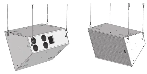
WARNING: Do not under any circumstances use a loudspeaker’s handles to support the weight of the loudspeaker except for their intended use: hand carrying. The handles are not rated to support the load of the loudspeaker for temporary or permanent installation.The VQ range of loudspeakers is intended to be suspended or ground-stacked. This section details how to physically configure VQ flatware and arrays. The following are the recommended methods for most situations. Specific situations may require other methods. It is the user’s responsibility to determine the viability and safety of alternate methods and implement them accordingly.
Flying A Single VQ Cabinet Using Eyebolts
The simplest method of flying a single VQ cabinet is with a pair of M10 shoulder eyebolts on the top, using a third eyebolt on the rear of the cabinet to tilt the cabinet.
VEB FORGED EYEBOLT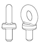 VQ loudspeakers can be flown with high-quality VEB M10 eyebolts with a collar to BS4278:1984. The loudspeakers are equipped with internal steel braces, which also double the flying points, and accept VEB M10 eyebolts.
To install the VEB M10 eyebolts remove the original M10 countersunk screws from the locations you wish to install the VEB M10 eyebolts. Then replace these countersunk M10 screws with the VEB M10 eyebolts. The M10 insert on the rear of the cabinet also accepts a VEB M10 eyebolt and should be used for tilting the loudspeaker to the desired angle.![]() IMPORTANT: It is imperative for safety reasons that a minimum of two eyebolts linked to two independently fixed straps are used per cabinet. Never suspend one enclosure from the other using eyebolts.Never attempt to use formed eyebolts i.e. formed from a steel rod and bent into an eye.Flying a single VQ cabinet in landscape orientation using EBS forged Eyebolts
IMPORTANT: It is imperative for safety reasons that a minimum of two eyebolts linked to two independently fixed straps are used per cabinet. Never suspend one enclosure from the other using eyebolts.Never attempt to use formed eyebolts i.e. formed from a steel rod and bent into an eye.Flying a single VQ cabinet in landscape orientation using EBS forged Eyebolts
VQ Flying Bracket (Single Point Hang Flying Bracket)
For safe, flexible, and simple flying, the VQ Flying bracket is designed to suspend the VQ cabinet from a single pivot point. This allows precise adjustment of aiming angles with the cabinet in situ. The flown VQ loudspeaker must be provided with an independent, correctly rated, and securely attached secondary safety – in addition to the principle hardware device. This secondary safety must prevent the loudspeaker from dropping more than 150mm (6”) should the principal hardware device fail.Note: All fixings should be thread-locked and torqued to 25 Nm.
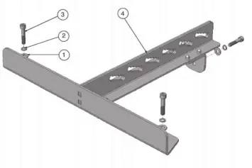
| Item No. | Description | Quantity |
| 1 | M10 Plain Washer | 3 |
| 2 | M10 Spring Washer | 3 |
| 3 | Screw M10 x 50mm | 3 |
| 4 | Bracket Flying – VQ | 1 |
The rod end is used in conjunction with the VQ flying bracket. Two types of rod ends are available. One is designed to accept ½” UNC threaded rod, and the other accepts 12 mm threaded rod. (Threaded rod supplied by user).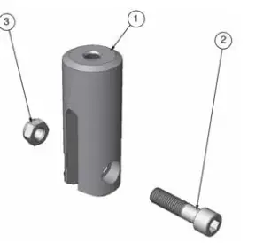
| Item No. | Description | Quantity |
| 1 | Rod End – VQ _” UNC or 12mm | 3 |
| 2 | Screw M12x45 Cap Head | 3 |
| 3 | M12 Nyloc Nut | 3 |
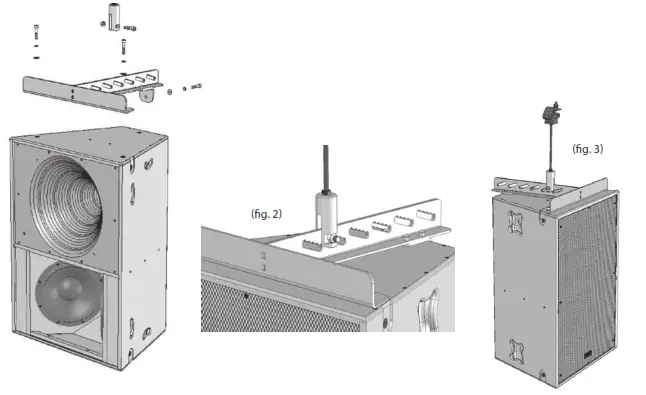
Remove the front two countersunk M10 screws located on the top of the cabinet and the top M10 countersunk screw on the top rear of the cabinet. Assemble the flying bracket as shown. (See fig. 1)
IMPORTANT: Only the screws, fasteners, shake-proof and plain washers supplied should be used to assemble the VQ flying bracket. Note: All fixings should be thread-locked and torqued to 25 Nm.
When fixed in position the rod end can be moved along any of the five serrated edges within each slot to fine-tune the loudspeaker tilt angle. (See fig. 2) The threaded rod used should be no more than 300 mm (12″) in length. The user is responsible for supplying the correct threaded rod. The minimum specifications for the threaded rod are:-
USA – Grade B7 (1438 lbs, 650 kgs for ½” rod based on a safety factor of 10:1)Metric – Grade 10.9 (1459 lbs, 660 kgs for 12 mm rod based on a safety factor 10:1)
Use the appropriate nuts to lock the rod end to the threaded rod (supplied by the user). Use a Nyloc nut at the top of the threaded rod to secure the pole clamp (supplied by the user).
The threaded rod can be attached to a suitably rated Uni-Strut accessory.
Always use Nyloc nuts to secure the threaded rod to the pole clamp or Uni-Strut.
The rigging of a flown sound system may be dangerous unless undertaken by qualified personnel with the required experience and certification to perform the necessary tasks.
Fixing of hanging points in a roof should always be carried out by a professional rigger and in accordance with the local rules of the venue. A maximum of VQ 60 + VQ MB + VQ DF (350 lbs, 160 kg) can be flown from a single-threaded rod. This combination carries a safety factor of 8:1. (See fig. 3)
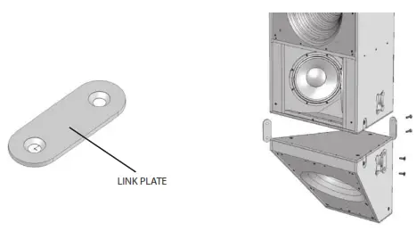
VQ Link Plate
The VQ link plate is used to join a VQ DF or VQ MB to a VQ 60 or VQ 100 cabinet. Three-link plates are used to connect each cabinet. The Link plates are supplied asstandard with each VQ DF and VQ MB.
Remove the M10 countersunk screws as shown in the diagram opposite. Use the same screws to fix the link plate in place. The link plate will sit flush in the cabinet indentations. Two longer M10 bolts are supplied with the link plates. These bolts should be used to fix the rear link plate in position.Note: All fixings should be thread-locked and torqued to 25 Nm
Using The VQ MB For Additional Pattern Control
The VQ link plate is used to join a VQ DF or VQ MB to a VQ 60 or VQ 100 cabinet. Three-link plates are used to connect each cabinet. The Link plates are supplied as standard with each VQ DF and VQ MB.
Remove the M10 countersunk screws as shown in the diagram opposite. Use the same screws to fix the link plate in place. The link plate will sit flush in the cabinet indentations. Two longer M10 bolts are supplied with the link plates. These bolts should be used to fix the rear link plate in position.

Arraying VQ 60
A single VQ 100 can produce more power and clarity over its 100-degree beamwidth area than many arrayed solutions using multiple cabinets, a great advantage when considering your building aesthetics. A VQ 100 is not designed to be arrayed.Two VQ 60s can be arrayed to produce a well-defined horizontal coverage angle of 120 degrees.The VQ array plate is designed to optimally array two VQ 60 cabinets. To fit the plate, set the boxes on the ground with the rear edge of the cabinets touching. Remove the two M10 countersunk bolts and replace them with either the M10 screw or the supplied eyebolts. Locate the four M10 eyebolts from the fixings kit supplied and insert these through the array plate into the rigging points in the cabinet. These will be used to pick up the array. Repeat the same procedure at the bottom of the cabinets, use the M10 screw. If flying in landscape orientation the M10 screw can be used on both array plates.Note: All fixings should be thread-locked and torqued to 25 NmTwo independent pick-up points are recommended for suspending the array. The main pickup points are the two rear eyebolts. The two front eyebolts may be used as safety points.
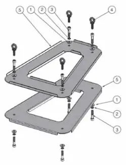
| Item No. | Description | Quantity |
| 1 | M10 Plain Washer | 8 |
| 2 | M10 Spring Washer | 8 |
| 3 | Screw M10 x 50 mm | 8 |
| 4 | Eyebolt M10 | 4 |
| 5 | Array Bracket | 2 |
Specifications
|
System |
VQ 100 | VQ 60 |
VQ 85DF |
| Frequency response (-3 dB) | 115 Hz – 23 kHz | 115 Hz – 23 kHz | 400 Hz – 23 kHz |
| Frequency range (-10 dB) | 90 Hz – 27 kHz | 90 Hz – 27 kHz | 350 Hz – 27 kHz |
| Sensitivity (1 W @ 1 m) | 111 dB | 115 dB | 111 dB |
| Dispersion (-6 dB) | 100 degrees conical | 60 degrees conical | 80 x 50 degrees |
| Driver components | LF – 2 x 300 mm (12″) low frequency transducers, semi horn loaded | LF – 2 x 300 mm (12″) low frequency transducers, semi horn-loaded | N/A |
| MF/HF – dual concentric compression driver loaded into single PSW waveguide | MF/HF – dual concentric compression driver loaded into single PSW waveguide | MF/HF – dual concentric compression driver loaded into single PSW waveguide | |
| Crossover | N/A | Biamp – 450 Hz (active), 7 kHz (passive)
Trump – 450 Hz, 7 kHz (active) |
Single amplified – 7 kHz (passive) Bi-amp – 7 kHz (active) |
| Directivity factor (Q) | 8.5 | 21.2 | 13.3 |
| Directivity Index (DI) | 9.3 | 13.3 | 11.2 |
| Maximum SPL | 135 dB averaged, 141 peak | 138 dB averaged, 144 dB peak | 134 dB averaged, 140 peak |
| Power handling | |||
| LF @ 4 Ω | 1000 W cont, 2000 W peak | 1000 W cont, 2000 W peak | N/A |
| MF @ 8 Ω | 200 W cont, 400 W peak | 200 W cont, 400 W peak | 200 W cont, 400 W peak |
| HF @ 8 Ω | 90 W cont, 180 W peak | 90 W cont, 180 W peak | 90 W cont, 180 W peak |
| Passive MF/HF @ 8 Ω | 200 W cont, 400 W peak | 200 W cont, 400 W peak | 200 W cont, 400 W peak |
| Nominal impedance | LF – 4 Ω, MF – 8 Ω, HF – 8 Ω | LF – 4 Ω, MF – 8 Ω, HF – 8 Ω | MF – 8 Ω, HF – 8 Ω |
Enclosure
| Construction | 18 mm (0.71″) birch plywood, internally braced | ||
| Grille | Powder-coated perforated steel grille | ||
| Finish | Textured black or white paint | ||
| Connectors | Barrier strip and Speakon connector | ||
| Fittings | 8 x recessed carrying handles, 12 x M10 flying inserts | 2 x recessed carrying handles, 12 x M10 flying inserts | |
| Dimensions | 925 x 694 x 515 mm
(36.4 x 27.3 x 20.3″) |
925 x 694 x 515 mm
(36.4 x 27.3 x 20.3″) |
500 x 694 x 515 mm
(19.7 x 27.3 x 20.3″) |
| Weight | 65 kg (143 lbs) | 77 kg (169 lbs) | 27.0 kg (59.4 lbs) |
| System | VQ 64DF | VQ 64MH | VQ MBSystem |
| Frequency response (-3 dB) | 400 Hz – 23 kHz | 400 Hz – 23 kHz | 115 Hz – 500 Hz |
| Frequency range (-10 dB) | 350 Hz – 27 kHz | 350 Hz – 27 kHz | 90 Hz – 600 Hz |
| Sensitivity (1 W @ 1 m) | 114 dB | 115 dB | 105 dB |
| Dispersion (-6 dB) | 60 x 40 degrees | 60 x 40 degrees | N/A |
| Driver components | N/A | N/A | LF – 2 x 300 mm (12″) low frequency transducers, semi horn loaded |
| MF/HF – dual concentric compression driver loaded into single PSW waveguide | MF/HF – dual concentric compression driver loaded into single PSW waveguide | N/A | |
| Crossover | Single amplified – 7 kHz (passive) Bi-amp – 7 kHz (active) | Single amplified – 7 kHz (passive) Bi-amp – 7 kHz (active) | N/A |
| Directivity factor (Q) | 19.3 | 21.3 | N/A |
| Directivity Index (DI) | 12.9 | 13.3 | N/A |
| Maximum SPL | 137 dB averaged, 143 peak | 138 dB averaged, 144 peak | 135 dB averaged, 141 peak |
| Power handling | |||
| LF @ 4 Ω | N/A | N/A | 1000 W cont, 2000 W peak |
| MF @ 8 Ω | 200 W cont, 400 W peak | 200 W cont, 400 W peak | N/A |
| HF @ 8 Ω | 90 W cont, 180 W peak | 90 W cont, 180 W peak | N/A |
| Passive MF/HF @ 8 Ω | 200 W cont, 400 W peak | 200 W cont, 400 W peak | N/A |
| Nominal impedance | MF – 8 Ω, HF – 8 Ω | MF – 8 Ω, HF – 8 Ω | LF – 4 Ω |
Enclosure
| Construction | 18 mm (0.71″) birch plywood, internally braced | ||
| Grille | Powder-coated perforated steel grille | ||
| Finish | Textured black or white paint | ||
| Connectors | Barrier strip and Speakon connector | ||
| Fittings | 2 x recessed carrying handles, 12 x M10 flying inserts | ||
| Dimensions | 500 x 694 x 515 mm
(19.7 x 27.3 x 20.3″) |
510 x 694 x 515 mm
(20.1 x 27.3 x 20.3″) |
433 x 694 x 515 mm
(17.1 x 27.3 x 20.3″) |
| Weight | 29.5 kg (64.9 lbs) | 45.5 kg (100.1 lbs) | 37 kg (81.6 lbs) |
Other important information
Important information
- Register online. Please register your new Music Tribe equipment right after you purchase it byvisiting musictribe.com. Registering your purchase using our simple online form helps us to process your repair claims more quickly and efficiently. Also, read the terms and conditions of our warranty, if applicable.
- Malfunction. Should your Music Tribe Authorized Reseller not be located in your vicinity,you may contact the Music Tribe Authorized Fulfiller for your country listed under “Support” at musictribe.com. Should your country not be listed, please check if your problem can be dealt with by our “Online Support” which may also be found under “Support” at musictribe.com.Alternatively, please submit an online warranty claim at musictribe.com BEFORE returning the product.
- Power Connections. Before plugging the unit into a power socket, please make sure you are using the correct mains voltage for your particular model. Faulty fuses must be replaced with fuses of the same type and rating without exception.
FEDERAL COMMUNICATIONS COMMISSION COMPLIANCE INFORMATION
TannoyVQ Series
| Responsible Party Name:Address:Phone Number: | Music Tribe Commercial NV Inc. 901 Grier DriveLas Vegas, NV 89118 USA+1 702 800 8290 |
VQ Seriescomplies with the FCC rules as mentioned in the following paragraph:
This equipment has been tested and found to comply with the limits for a Class B digital device, pursuant to part 15 of the FCC Rules. These limits are designed to provide reasonable protection against harmful interference in a residential installation. This equipment generates, uses and can radiate radio frequency energy and, if not installed and used in accordance with the instructions, may cause harmful interference to radio communications. However, there is no guarantee that interference will not occur in a particular installation. If this equipment does cause harmful interference to radio or television reception, which can be determined by turning the equipment off and on, the user is encouraged to try to correct the interference by one or more of the following measures:
- Reorient or relocate the receiving antenna
- Increase the separation between the equipment and receiver
- Connect the equipment into an outlet on a circuit different from that to which the receiver is connected
- Consult the dealer or an experienced radio/TV technician for help
This device complies with Part 15 of the FCC rules. Operation is subject to the following two conditions:
- this device may not cause harmful interference, and
- this device must accept any interference received, including interference that may cause undesired operation.
Important information:Changes or modifications to the equipment not expressly approved by Music Tribe can void the user’s authority to use the equipment.
 report this ad
![]()
References
[xyz-ips snippet=”download-snippet”]