
TAUREAN Door Systems Novataur Commercial Roller Door

Extreme safety warning: Safe practices must be observed when working at heights, lifting roller doors and adjusting roller door spring tension
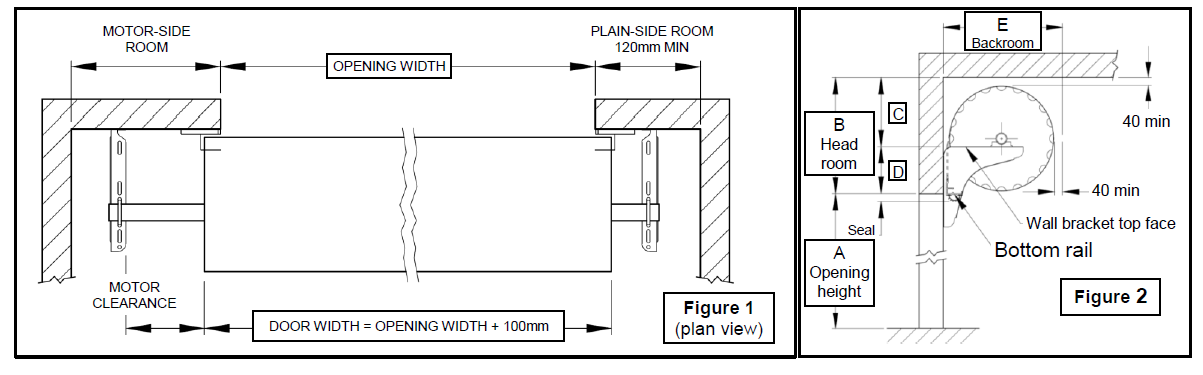
- Check DOOR WIDTH against OPENING WIDTH (Figure 1). For a standard installation the roller door curtain should be at least 100mm wider overall than the opening.
- Check SIDE-ROOM (Figure 1). If a motor is to be installed, ensure there is also enough clearance between edge of curtain and bracket (refer to manufacturer’s instructions).Chain-operators (direct-drive or planetary-gear) require 90mm MOTOR CLEARANCE and 195mm MOTOR SIDE ROOM.
- Check the HEAD-ROOM B and BACK-ROOM E (Figure 2 and Table 1)
- Mark the horizontal position for the wall brackets. They should be positioned well clear of the curtain edge, guide tracks, and any track brackets. The flanges normally point towards the roller door.
- Mark the vertical position of the wall brackets above the opening (Figure 2 D). Level the two brackets at the door mounting faces using a water level or other suitable device
- Attach the wall brackets to the wall:
- Only self-drilling screws and wood fixing screws are supplied in the kit box (no expanding or masonry bolts). The installer must assess what is appropriate in each situation.
- If welding installer must verify weld integrity and strength.
- If screw fastened: oFor steel purlins: four or more self-drilling screws must be used to secure each bracket. oFor timber frame: three or more 8mm x 50mm coach screws must be used per bracket. oFor brick or concrete: depending on the type and condition of the wall, use three or more long M8 bolts (or threaded rod) from the outer surface of the wall, or 10mm (M8 thread) metal expansion fasteners (eg Loxin or Dynabolt).
- Flat washers must be used under all nuts and all bolt and screw heads.
- A screw or bolt must be fitted to the very top slot. Select other slot positions evenly spaced up the bracket flange as required.
- Option: mount motor loosely onto the axle at the required end (the coloured side of the door faces outwards)with the drive disengaged.
- If installing a chain-operator (direct-drive or planetary-gear), bolt the chain wheel (or plastic ring gear) to the drum wheel at the correct end of the door using the 3 bolts, nuts, and washers provided.
- Fit the chain-guide loosely to the axle, oriented with the tubes positioned vertically in-line with the chain sprockets in the chain wheel. The clamp screw is to be tightened only after final spring tensioning is completed.
- For a planetary gear chain operator, the gear assembly and chain wheel is pushed towards the door to fully mesh with the ring gear and a Ø9.5mm hole is drilled through the axle using the drive hub as a guide. The chain drive is fastened with the bolt and nut provided.
- The chain itself may be fitted now or later. Pass the chain over the chain wheel and through the chain guide. Cut an end link and bend it open to join at the desired length, then bend it closed again. Fasten the chain cleat to the drive-side wall.
- Centre the axle by rotating a ¼ turn then releasing. Mark the axle where the drum wheel sits in the relaxed state. There should be an equal length of axle at each end
-
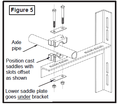
Lift the roller door onto the brackets and loosely secure the axle to the brackets using two cast saddles (with the slots offset towards the door), keeper plates, and high-tensile bolts, nuts and washers at each end of the door. The lower keeper plate is fitted under the bracket.Extreme safety warning: Safe practices must be observed when lifting roller doors as they can be very heavy. The installer must ensure the roller door is secure and supported at all times. The door is to be placed onto both brackets at the same time. The wall brackets are designed to support only a horizontal door and using them to mount door lifting gear is not recommended by Taurean. Any injury or damage arising from this practice will be the installer’s responsibility and is not covered by the door warranty. MOTOR-SIDE ROOM OPENING WIDTH DOOR WIDTH = OPENING WIDTH + 100mmFigure 1 (plan view) PLAIN-SIDE ROOM 120mm MIN MOTOR CLEARANCE Figure 2CDWall bracket top face40 minA Opening height 40 minBottom railB Head roomE BackroomSeal
-
Centre the roller door on the axle with the same amount of curtain overlap at each side of the opening and position the motor. Rocking the roller door on its axle will assist the door to move into position. Ensure the drum sits on the axle as marked in Step 12.
-
Move the door to the rear of the bracket slots and, without cutting through to the centre nylon strap, remove all other packaging material.

- Turn the axle to allow the door to be relaxed on the axle with the bottom rail at the bottom of the curtain (6 o’clock position). Hold the door and give the axle a ½ turn of tension (see Figure 3). Fully tighten the axle clamps.
- Apply 1 turn of spring pre-tension by turning the curtain roll over the top and hold in this position (Figure 3). There is now 1.5 turns of pre-tension.
- Without letting go of the curtain,cut the centre strap and remove packaging. Holding the centre of the bottom rail, the curtain may now be fully opened and closed to ensure the roller door is rolling up in correct alignment on the roll (ie, the ends of the rolled curtain must be square andnot ‘coned’) prior to fitting the Guide Tracks. Take care to avoid the nylon braiding or the door curtain touching the wall.
- The door should have a small amount of lift when in the open position and so a softwood chock may now be carefully positioned (Figure 3) between the Bottom Rail and the curtain roll to prevent the door rolling up
- Cut the bottom of the tracks to suit the opening height. The underside of the top stop is normally level with the top of the opening (Figure 2). The weather seal will protrude ~20mm into the opening when the door is open. The top of the track should be at least 100mm above the wall bracket.
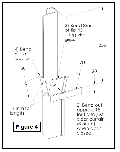
- Flare out and trim both the side and rear faces at the track lead-in (Figure 4). Nick the safety edge in two places to allow bending. After fitting the tracks, if necessary, adjust the angles so the curtain enters the track smoothly. If the door is installed high bend the top edge of the track away to avoid catching the nylon braiding.
- Mount the tracks to the wall. Lower the door to the closed position and slide the tracks in from the side until there is a 3-6mm gap between the track and the black plastic piece at the end of the Bottom Rail. Ensure the tracks are vertical then fix to the wall by screwing or welding as appropriate.
- Note: Before fully fastening the tracks, operate the door fully to ensure it is not binding in the tracks at any point.
- Adjust the door-axle to the optimal position on the mounting brackets. Work with the door in the open position and only loosen one end at a time. Loosen the clamp and move the door towards the wall until just about touching the track front face but avoiding any binding. Ensure both clamps are fully re-tightened. (Figure 5).
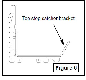
- Install both of the optional top stop catcher brackets (Figure 6) at each end of the bottom rail using the supplied dome-head bolt and nut. Mark using the bracket as a guide and drill.
- Check the door balance: When correctly balanced, the roller door should have a tendency to lift slightly at the top and bottom positions and be neutral or slightly heavy at mid height.
- If necessary, adjust the springs (Figure 3)With the door in the open position, loosen one clamp. Then, while preventing the axle from turning with a pipe wrench, loosen the other clamp. The handle of the wrench will want to lift towards the ceiling. Turn the axle in the direction required to adjust the spring tension: raise the wrench to make the door ‘heavier’, lower to ‘lighten’. This is a potentially hazardous step and should only be attempted by a competent tradesperson. Ensure both clamps are fully re-tightened before operating door.
- Complete motor installation and setup to the manufacturer’s instructions.
- Fit the optional centre lock. Remove the protective film from this area, position the lock front in the panel holes and hold or tape to the outside of the door. From the back of the door, orient the lock with the writing the ‘right way up’ and screw to the lock front with the 2 screws supplied. With the door in the fully closed position, mark the height positions of the locking bar and cut a hole in each track for the locking bars to slide through. With the lock arms fully retracted, temporarily fit the 2 locking bars to the lock arms then mark the correct length. Cut each bar to length and chamfer-cut the corners for a lead-in. Then install the locking bars through the PVC guides ensuring that any supplied anti-rattle grommets are fitted and screw them to the lock arms. Check the lock operation.
- Remove any protective film from the outside face of the curtain.
- Fit the optional waist-high slide-lock at a suitable height. When withdrawn the locking bar must not extend beyond the door curtain. Use the assembly as a drilling guide and attach with the rivets provided. With the door in the fully closed position, mark the height positions of the lockingbar and cut a hole in each track for the locking bars to slide through.
- Refer to Taurean website www.taureands.com.au for Product Warranty and Stramit Corporation Pty Ltd Roller Door Warranty and Exclusion of Liability Statement

 With the door in the open position, loosen one clamp. Then, while preventing the axle from turning with a pipe wrench, loosen the other clamp. The handle of the wrench will want to lift towards the ceiling. Turn the axle in the direction required to adjust the spring tension: raise the wrench to make the door ‘heavier’, lower to ‘lighten’. This is a potentially hazardous step and should only be attempted by a competent tradesperson. Ensure both clamps are fully re-tightened before operating door.
References
[xyz-ips snippet=”download-snippet”]