tc electronic Spatial Expander Plug User Manual
TC1210 NATIVE / TC1210-DT
Unique Spatial Expander Plug-in with Optional Hardware Controller and Signature Presets Rev
 Terminals marked with this symbol carry electrical current of sufficient magnitude to constitute risk of electric shock. Use only high-quality professional speaker cables with ¼” TS or twist-locking plugs pre-installed. All other installation or modification should be performed only by qualified personnel.
This symbol, wherever it appears, alerts you to the presence of uninsulated dangerous voltage inside the enclosure – voltage that may be sufficient to constitute arisk of shock.
 This symbol, wherever it appears, alerts you to important operating and maintenance instructions in the accompanying literature. Please read the manual.
CautionTo reduce the risk of electric shock, do not bremove the top cover (or the rear section). No user serviceable parts inside. Refer servicing to qualified personnel.
CautionTo reduce the risk of fire or electric shock, do not expose this appliance to rain and moisture. The apparatus shall not be exposed to dripping or splashing liquids and no objects filled with liquids, such as vases, shall be placed on the apparatus.
CautionThese service instructions are for use by qualified service personnel only. To reduce the risk of electric shock do not perform any servicing other than that contained in the operation instructions. Repairs have to be performed by qualified service personnel.
- Read these instructions.
- Keep these instructions.
- Heed all warnings.
- Follow all instructions.
- Do not use this apparatus near water.
- Clean only with dry cloth.
- Do not block any ventilation openings. Install in accordance with the manufacturer’s instructions.
- Do not install near any heat sources such as radiators, heat registers, stoves, or other apparatus (including amplifiers) that produce heat.
- Do not defeat the safety purpose of the polarized or grounding-type plug. A polarized plug has two blades with one wider than the other. A grounding-type plughas two blades and a third grounding prong. The wide blade or the third prong are provided for your safety. If the provided plug does not fit into your outlet, consult anelectrician for replacement of the obsolete outlet.
- Protect the power cord from being walked on or pinched particularly at plugs, convenience receptacles, and the point where they exit from the apparatus.
- Use only attachments/accessories specified by the manufacturer.
- Use only with the cart, stand, tripod, bracket, or table specified by the manufacturer, or sold with the apparatus. When a cart is used, use caution when moving the cart/apparatus combination to avoid
- Unplug this apparatus during lightning storms or when unused for long periods of time.
- Refer all servicing to qualified service personnel. Servicing is required when the apparatus has been damaged in any way, such as power supply cord or plug is damaged, liquid has been spilled or objects have fallen into the apparatus, the apparatus has been exposed to rain or moisture, does not operate normally, or has been dropped.
- The apparatus shall be connected to a MAINS socket outlet with a protective earthing connection.
- Where the MAINS plug or an appliance coupler is used as the disconnect device, the disconnect device shall remain readily operable.
- Correct disposal of this product: This symbol indicates that this product must not be disposed of with household waste, according to the WEEE Directive (2012/19/EU) and your national law. This product should be taken to a collection center licensed for the recycling of waste electrical and electronic equipment (EEE). The mishandling of this type of waste could have a possible negative impact on the environment and human health due to potentially hazardous substances that are generally associated with EEE. At the same time, your cooperation in the correct disposal of this product will contribute to the efficient use of natural resources. For more information about where you can take your waste equipment for recycling, please contact your local city office, or your household waste collection service.
- Do not install in a confined space, such as a book case or similar unit.
- Do not place naked flame sources, such as lighted candles, on the apparatus.
1. Introduction
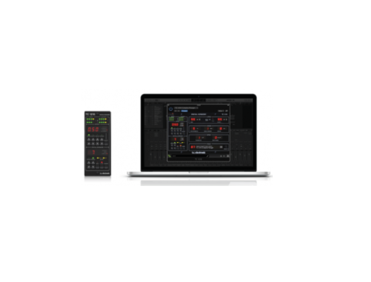
TC1210 is a thorough recreation of the famed TC 1210 Spatial Expander + Stereo Chorus Flanger rack unit – the same sound, the same feel, but with updated controls to fit in with a modern DAW-based workflow. Based on the original schematics and careful measurements of several refurbished units, the new TC1210 emulates the analog circuitry and innovative dual-engine modulation down to the very last detail. To make absolutely sure the sound, versatility and tone came out flawless, we even had studio pros and longtime 1210 users such as Tony Maserati work alongside our development team. And it really does sound fantastic both as a modulation effect and as a spatialexpander on anything from strings and keys to vocals, roaring drums, synths and expressive guitar tracks. TC1210 is a one-of-a-kind in the world of DAWs, just like the original was the absolute first of its kind when we designed it back in 1985. We hope you’ll enjoy it as much as we do!
About this manual
Read this manual to learn how to install and use your TC Electronic TC1210 Spatial Expander. This manual is only available in PDF format from the TC Electronicwebsite. To get the most from this manual, please read it from start to finish, or you may miss important information. To download the most current version of this manual, visit the web page: https://www.tcelectronic.com/Categories/c/Tcelectronic/Downloads If you still have questions about your TC Electronic product after reading itsmanual, please get in touch with TC Support: https://www.tcelectronic.com/brand/tcelectronic/support
2. Plug-in Installation
Visit www.tcelectronic.com/tc1210-dt/support/ to download the installer file. The plug-in requires either an iLok license (delivered when you purchase the NATIVE version) or the TC1210 DT Desktop Controller (when you purchase the DT Desktop Controller version) or an iLok Trial License. All parameters are available in the plug-in and most are available on the DT Desktop Controller. Select the Mac or PC version and save the file to your hard drive. The latest firmware for the TC1210 Desktop Controller will be included in the software as well.
2.1 Installation on a PC
Open the zip file and double click the executable file.Follow the steps in the Setup Wizard.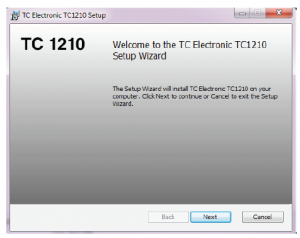
Accept the license agreement and click ‘Next’.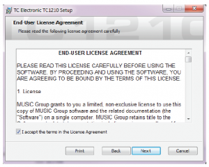 Select which VST and/or AAX components you want to install. Pro Tools uses AAX and most other DAW programs use VST. The installer will offer a defaultlocation to save the file, but you can choose another location by clicking the ‘Browse’ button.
 Click ‘Next’ to begin the installation.
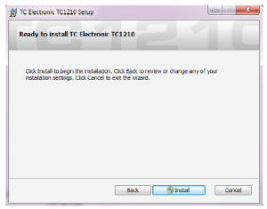
5 TC1210 User Manual
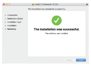
When installation is complete, click ‘Finish’.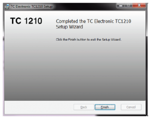
2.2 Installation on a Mac
Open the zip folder and double click the installer icon.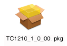
Proceed through the prompts to begin installation.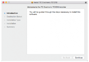
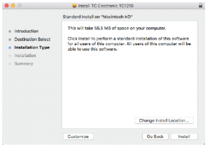
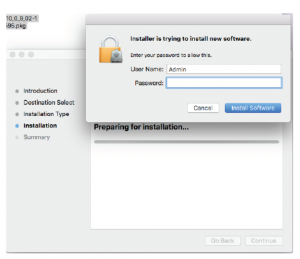
A default location will be selected for installation, or you can select another folder manually. If you have administrator authorization in place, you will need toenter your password before beginning installation.
3. Activate your TC1210 iLok License
3.1 Activate when you have purchased the NATIVE version
Step 1: Install iLokThe first step is to create an iLok user account at www.iLok.com and install the PACE iLok License Manager on your computer if it’s your first time using iLok.
Step 2: ActivationIn the received mail (when buying the NATIVE version) you will find your personal Activation Code. To activate your software, please use the Redeem an ActivationCode feature in the PACE iLok License Manager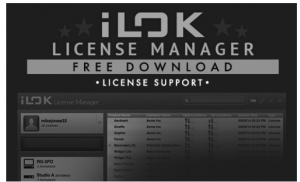
3.2 Get a Free Demo License
Make use of this hassle-free offer to try out our plug-ins before you buy.
- 14-Day Trial Period
- Fully Functional
- No Feature Limitations
- No Physical iLok Key Needed
Step 1: Install iLok
The first step is to create a free iLok user account at www.iLok.com and install the PACE iLok License Manager on your computer if it’s your first time using iLok.
Step 2: Get your free license
Go to http://www.tcelectronic.com/brand/tcelectronic/free-trial-TC1210-native and enter your iLok User ID.
Step 3: Activation
Activate your software in the PACE iLok License Manager.
4. Connection and Setup
4.1 Connecting the TC1210-DT Desktop Controller (when you have purchased the DT Desktop Controller version)
Getting the Desktop Controller up and running couldn’t get any easier. Plug the included USB cable into the unit’s rear micro-USB port, and connect the other end to a free USB port on your computer. The Desktop Controller is bus powered so no other power cables are necessary, and no additional drivers need to be manually installed.
The Desktop Controller will light up upon successful connection. You can now apply the plug-in to a channel in your DAW to begin using the effect. This processmay vary slightly depending on your software, but generally should require these steps:
- Select a channel or bus in your DAW to which you would like to add the effect Access the mixer page where you should see a section dedicated to effect slots
- Open the menu where you can select from a list of effect types, which probably includes many stock plugins that are included with the DAW. There should be submenu to view general VST/AU/AAX options.
- The plug-in will likely be found in a dedicated TC Electronic folder. Select the TC1210 and it will now be added to the signal chain.
Double click on the effect slot that contains the TC1210 to view the plug-in UI. There should be a green link icon at the bottom, and text that indicates successfulconnection between the plug-in and the Desktop Controller.
Note: The iLok License Manager needs to be installed on your computer also if you have purchased the DT Desktop Controller version. In this case you don’t needto create an iLok account or activate any license.
4.2 Operating the TC1210
After you have installed the plug-in, and either activated the iLok license or connected the TC1210-DT Desktop Controller via USB, you can begin inserting theplug-in to your tracks. Adjustments to the effect are done in two ways. Either by using the plug-in user interface or via the physical Desktop Controller.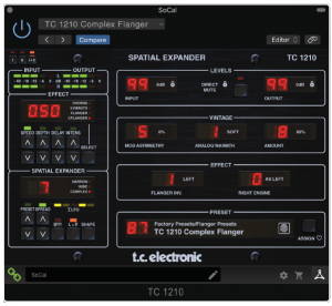
4.3 Insert vs Aux Effect
The TC1210 can be inserted directly into an effect slot on a single channel, as described above, which passes the entire signal through the effect. However, the TC1210 can also be added to an auxiliary bus, and one or more channels can send a portion of their signal to this bus to be processed by the effect. The output of the effect is then mixed back in with the rest of the tracks. This differs from an insert effect in that the TC1210 shouldn’t affect the track’s entire signal i.e. Direct Mute should be enabled.Note that in a send/aux setup, the TC1210 sound is dependent on the delay between the dry and the wet signal, which is controlled tightly within the plug-in itself. This means that the resulting sound is less controlled and is potentially DAW-dependent if used in send/aux setup. The DAW’s handling of latency through various plug-ins, the delay between the dry/master signal, and the wet send/aux signal may differ, and the resulting sound likewise may differ.
4.4 Mono/Stereo Operation
The TC1210 can be used both as a mono instance on mono tracks and a stereo instance on stereo tracks. Depending on the specific DAW, a mono in/stereo out mayalso be available. When the plug-in is instantiated on a mono-in mono-out track only left audio channel is processing. TC1210 is fully mono downmix compatible due to its true stereo dual engine topology with very controlled handling of delays and phase. This way, it ensures playback compatibility on mono systems like DAB radios, mobile devices and audio installations in shops and restaurants. TC1210 Laptop
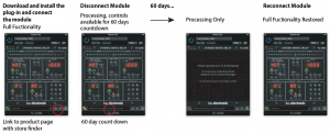
4.5 Travel Period and Module Connection (when you have purchased the DT version):
You can try out the plug-in before purchasing or receiving your purchased Desktop Controller by requesting a Free iLok Trial License, which will enable full functionalityfor 14 days. When you receive and connect your purchased Desktop Controller you will no longer need an iLok License to have full functionality in the plug-in or via theDesktop Controller.
60-day Travel Period
If the Desktop Controller is disconnected, full plug-in functionality will be available for 60 days, after which the plug-in requests re-connection to the hardware unit.Once the hardware unit is re-connected, all controls become available.
4.6 Primary and Secondary Controls
After you have installed the plug-in and activated the iLok license or connected the TC1210 via USB, you can begin adding the effect to your tracks.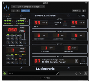
The plug-in is divided into two sections, which are both visible when the “I+II” button at the top left is selected. The left section is identical to the hardware unitand could be considered Primary parameters. These include common items such as depth, delay, and intensity. The right side contains the Secondary parameters.To reduce plug-in size on your screen you can select “I” or “II” in the top left of the plug-in. “I” will show the left section of the plug-in only and “II” will show the right section. Setting “II” can be a complementary setting when using the hardware unit.” All of these parameters will be discussed in detail later in this manual.
4.7 Connection Status to the Hardware Unit
The TC Icon family all use the same method to show the connection status between the plug-in and the hardware unit. Connection status is indicated on the lower left side of the plug-in window. Successful connection is indicated with a green chain icon. When using theNATIVE version only, this chain icon will remain grey.
There are 3 conditions that will result in a “Not connected” status. If another instance of the plug-in already exists on another track, the chain icon will appear yellow with a yellow frame, and the text box will notify you where the plug-in is currently active. Click the chain icon to connect the hardware unit to the new plug-in location. The yellow icon may also appear while the connection is being made between the TC1210 unit and the plug-in, accompanied by “Connecting…” text.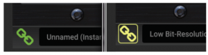
If the hardware unit is disconnected from the computer, but the countdown has not yet expired, a yellow chain icon without the yellow frame will appear.See “Travel Period and Module Connection” section for details.
All other “Not connected” states are indicated by a red chain icon. This could happen if the USB cable is disconnected, the TC1210 connection is disrupted,or other issues.
To summarize the connection status possibilities: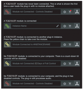
Most DAWs offer the ability to move or drag plug-ins from one track/bus to another, and TC1210 supports this as well. Most DAWs also feature an on/off switch for plug-ins, accessible inside the plug-in window and/or the track itself. Muting the plug-in will make the effect inaudible, but will not shut down the connection to use the hardware unit.
5. Plug-in and Hardware Controls
Control of the TC1210 is done in the plug-in or optionally done using the hardware unit (when you have purchased the DT version) . All primary parameters of the TC1210 are also accessible through the DT Desktop Controller. These include parameters that control major parts of the effect, such as speed, depth, and spread. Secondary parameters that are needed less-often are handled in the plug-in window.
5.1 Primary Plug-in and Hardware Controls
Meters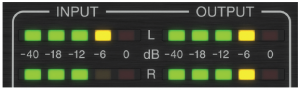
The meter section gives feedback about the incoming and outgoing audio signals. The input level displays the audio as it enters the plug-in, and is not affected by adjustments to the input level control or any other parameter. The output meter is affected by the results of the effect as well as the output level control parameter.
Effect Section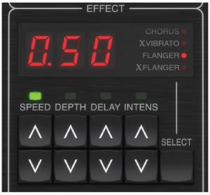
Press the SELECT button to rotate through the 4 effect styles. The red dot will indicate the current selection.Adjust the SPEED, DEPTH, DELAY and INTENSITY with the associate arrow buttons.The most recently adjusted parameter will have its green LED lit, and the parameter value will be displayed.SPEED controls the rate of sweep from one sweep every ten seconds (.10) to ten sweeps every second (10.0).DEPTH controls the depth of the modulation from 0 to 100%.DELAY controls the length of the delay time from approximately 1.2 ms to 11 ms.The INTENSITY control adjusts a different parameter depending on the selected effect:
- Chorus – mix level (output level if Direct Mute is engaged).
- X Vibrato – effect signal level.
- Flanger – signal regeneration (feedback).
- X Flanger – inversed signal regeneration.
Chorus
Intensity controls the mix level when Direct Mute is disengaged. With Direct Mute engaged, the plug-in will only output the modulated pitch change, and Intensity then controls level. Depth controls the amount of pitch change, and Speed controls the rate. The Delay parameter is not often found onChorus effects. It moves and “sets” the number of comb filter notches. At high delay times, there are more comb filter notches and it may have a pronounced affect on low frequency signals.
X Vibrato
This effect takes over where the Chorus left off. At max Intensity, the effect is Vibrato (the full signal is modulated). At minimum Intensity, the effect is Chorus when mixed with the Direct (dry) signal. At high delay times, there are more comb filter notches and it may have a pronounced affect on low frequency signals.
Flanger
This is a classical Flanger, which can further be underlined in the Narrow Shape setting. By design, the Flanger effect mainly affects mid frequencies and does not tend to get muddy or out of control. The Intensity parameter affects Flanger feedback. Max Intensity results in max feedback, giving a more pronounced flanging effect. Flanger Invert (found on the plug-in window) inverts the feedback in the Flanger effect. This puts a gentle spectral notch at DC in the feedback, resulting in a slightly brighter quality to the ringing part of the effect. It affects the sound primarily at short delay settings where the notches are fairly spread in the frequency spectrum.
X Flanger
At the Narrow Shape setting, the Flanger and X Flanger effects are fairly identical except for some left-right cross mixing. In Wide Shape mode, X Flanger has a more controlled sound with less pitch-shifted tails than Flanger. The X Flanger may be preferable over the typical Flanger sound. It becomes wider, larger sounding than e.g. Chorus with less ringing tails. In Complex Shape mode, X Flanger is much more complex with unpredictable pitching tails. Chaos is readily available. Intensity and Flanger Invert parameters have identical behavior to the Flanger effect.
Delay
The Delay parameter follows the original TC1210 product, and the range is approximately 1.2 ms to 11 ms. The Delay parameter is not an often available parameter in Chorus/Flanger effects. It moves and “sets” the number of comb filter notches. At high delay times there are more comb filter notches and it mayhave a pronounced affect on low frequency signals.
Spatial Expander Section
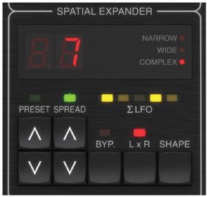
Shape
Press the SHAPE button to rotate through the 3 expander types:
- Narrow – the two modulation signals are combined to a common signal that will modulate both the left and right audio channel. The modulation amount is set by Speed, Depth, Delay, Intensity and the Spread parameters.
- Wide – the two modulators are combined similar to Narrow mode, but one is phase-inverted to the other before they modulate each audio channel.This means that while the left channel is pitch shifted down, the right channel is pitch shifted up and vise versa. It also means that the general pitch of the signal is not affected.
- Complex – the two modulation engines are now fully decoupled and running asynchronously. It results in a more complex and organic-sounding modulation pattern.
Sigma LFO meter
The Sigma LFO meter is designed to give a visual representation of the TC1210 modulation engines and how the modulation audibly affects the signal. In Narrow Shape mode, where the two modulation signals are combined to a common signal that will modulate both left and right channels, only the center LED is pulsing. The pulse pattern reflects the settings of the modulation engines e.g. Speed, Depth and the Spread setting that defines how much the two modulation engines are spread apart. When Spread is set to a high value, 2 modulation signals will affect the Sigma LFO meter’s middle LED. In Wide Shape mode, the two modulators are combined like in Narrow mode, but one is phase-inverted to the other before they modulate each audio channel. On the Sigma LFO meter, all 5 LEDs can potentially be active, representing spatial wideness in the resulting audio output, depending on Speed, Depth and Spread. When Spread is set to a high value, two modulation signals will be clearly visible on the Sigma LFO meter. In Complex Shape mode, the two modulation engines are now fully decoupled and running asynchronously. This results in a more complex and organicsounding modulation pattern. On the Sigma LFO meter, all 5 LEDs can potentially be active, representing spatial wideness in the resulting audio output, depending on Speed, Depth and Spread. When Spread is set to a high value, two modulation signals will be clearly visible on the Sigma LFO meter.
LxR
The LxR button turns the cross mixing of the output channels on and off. The cross mixed signals are gained internally to approx -6 dB in order to keep solidcontrol of unintentional phase issues.
Spread
The SPREAD parameter defines how far apart the left and right modulation engines are spread from each other. When maximally spread, the two modulations each become more clearly defined, both on the Sigma LFO meter and in the audible results. SPREAD is defined in 3 “gears”. 0 though 3, 10 through 13 and 20 through 23.These 3 gears define the speed in the right channel relative to the manual settings dialed in on the hardware module for the left channel. 0 though 3 (10..13 and 20..23) define how Intensity, Depth and Delay are set in the right channel relative to the left channel.
Spread |
Speed |
Depth |
Delay |
Intensity |
| Factor R/L: | Factor R/L: | Factor R/L: |
Factor R/L: |
|
|
0 |
1 or 0.96* | 1 or 0.5* | 1 or 0.707* |
1 or 1.25* |
|
1 |
0.96 | 0.75 | 0.707 |
1.25 |
|
2 |
0.96 | 1 | 0.707 |
1.25 |
|
3 |
0.96 | 1 | 0.707 |
1.5 |
|
10 |
0.55 | 0.5 | 0.707 |
1.25 |
|
11 |
0.55 | 0.75 | 0.707 |
1.25 |
|
12 |
0.55 | 1 | 0.707 |
1.25 |
|
13 |
0.55 | 1 | 0.707 |
1.5 |
|
20 |
0.145 | 0.5 | 0.707 |
1.25 |
|
21 |
0.145 | 0.75 | 0.707 |
1.25 |
|
22 |
0.145 | 1 | 0.707 |
1.25 |
|
23 |
0.145 | 1 | 0.707 |
1.5 |
Bypass
The effect can be easily BYPASSED to audition the results of the settings against the unaffected audio.
Preset
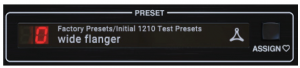
Select the PRESET with the arrow keys. The green LED will light above the keys and the display will show the current preset. See Chapter 5 for more details.
5.2 Plug-in Controls – Secondary Parameters
Levels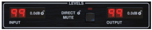
Click and drag up or down to adjust the input and output levels from 0 to 99. A setting of 0 is -∞, and a setting of 1 is -96 dB. The level increases in 3 dBincrements at low settings, and by 0.5 dB increments above -40 dB. DIRECT MUTE is for disabling the direct (dry) sound through the plug-in.This is typically done either for enhancing the effect set to e.g. Vibrato / detune or if the plug-in is used as a send/aux effect where the dry sound is going to theDAW project master output directly. Note in send/aux setup that the 1210 sound is dependent on the delay between the dry and the wet signal, which in insertmode in the DAW project is controlled tightly within the plug-in itself. This means that the resulting sound is less controlled and is potentially DAW-dependent if used in send/aux setup. The DAW’s way of handling latency through various plug-ins, the delay between the dry/master signal, and the wet send/aux signal may differ, and the resulting sound likewise may differ.
Vintage
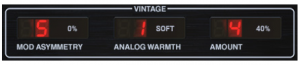
The MODULATION ASYMMETRY parameter was not included in the original TC1210. At 0% setting (5), the modulation waveform is modeled tightly against the original TC1210. The original waveform was carefully designed and is rather complex by nature. Despite the already smooth-sounding modulation engine, creative options existby using MODULATION ASYMMETRY. ANALOG WARMTH and AMOUNT closely recreate parts of the original analog schematics. For an optimally clean sounding signal path, e.g. a full mix signal, set the ANALOG WARMTH to OFF. Soft and Medium settings select between two different signal saturation circuits that add character to the sound, while AMOUNT sets the signal level threshold where the saturation kicks in.
Effect
The flanger feedback can be inverted on the left or right channel, both or neither. Flanger Invert only affects the TC1210 when Flanger or X Flanger effects are selected in either of the engines. This inverts the feedback in the Flanger effect, putting a gentle spectral notch at DC in the feedback, resulting in a slightly brighter quality to the ringing part of the effect. It affects the sound primarily at short delay settings where the comb filter notches are fairly spread in the frequency spectrum.The Right Engine parameter sets which effect is running in the right audio channel. Selecting ‘As Left’ causes both effect engines to run the effect that has been selected on the hardware module.
 Lock SymbolSome of the parameters can be locked from being recalled when a new preset is selected. Locked parameters will always keep their values no matter which preset you recall. It is especially useful to lock Direct Mute, which should always be enabled when TC1210 is used on an aux send. This eliminates potential phase issues on the direct signal that is also sent to the DAW project’s master output.Preset
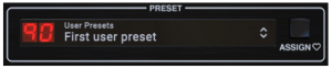
Use the PRESET section to recall and save presets as well as assign presets as favorites. See Chapter 5 for details.
Bottom Section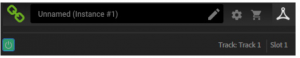
The bottom portion of the plug-in window displays connection status as well as plug-in instance name, and has several options available. The green chain icon indicates successful connection between the hardware unit and the plug-in. Connection issues will be indicated by yellow or red icons; see Chapter 3 for details. The current name of the plug-in instance appears in the middle field. If the DAW is able to provide the name of the track where the plug-in instance is inserted, the plug-in instance will be named after the track name. The instance can be renamed by clicking the pencil icon.
If you install the plug-in without connecting the hardware unit to your computer, a red dot will appear on the shopping cart icon. This will link you to more information about buying the TC1210 unit. Once the plug-in detects a connected hardware unit, the red dot will disappear The Settings icon accesses a menu with several links and options. This user manual is available, along with links to the TC Electronic website, relevant news, additional signature presets, and the user license agreement.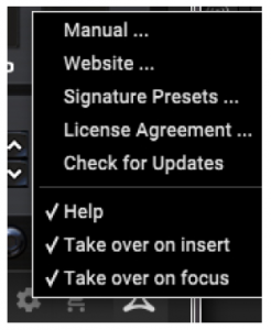
If a red dot appears over the Settings icon, a new version of the plug-in or firmware may be available. Click “Check for Updates” to download and install thenew file. See Chapter 6 for details
With the “Help” option selected, hovering the mouse over a certain item in the plug-in window will give a brief description of the parameter’s function. With the “Take over on focus” option selected, the currently-viewed plug-in instance will take over control of the physical hardware unit as soon as it is brought into focus.When a new instance of the plug-in is inserted on a track or bus, that instance will take over immediately if the “Take over on insert” option is checked.
6. Presets
The TC1210 offers a collection of default and signature presets, as well as the option to create and save your own custom settings.Note that most DAWs have a built-in preset function that appears on every plug-in, which is often found at the top of the plug-in window.
Favorite Preset
A single click on the Preset window brings up a menu with several preset-related options. Recall a factory or user preset from the libraries, save the current preset,or create a new user preset with the ‘Save as’ option.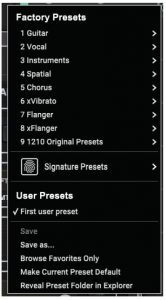
The presets menu is divided between a Factory Presets and a User Presets section. The Factory Presets are built into the plug-in and cannot be overwritten, so if afactory preset is modified and you’d like to keep the changes, you need to save it as a user preset. User Presets can be edited and organized as you’d like. The Factory Presets section includes a sub-section called Signature Presets. Signature Presets are custom-made presets designed by world-class artists and recording engineers. The library of signature presets is constantly being expanded, and you can check for more Signature Presets that might be available for download by accessing the Settings menu and selecting ’Signature Presets’. Factory, Signature, and User presets have unique icons that appear next to the preset name.
When recalling a default or saved preset, the name will appear in plain text as shown. However, as soon as you make an alteration to any of the parameters in that preset, the text changes to italics to indicate a deviation. This is also indicated by a red dot after the preset number. You can click in the PRESET window, then select the Save option, or discard the changes when you navigate away from that preset.
Favorite Preset
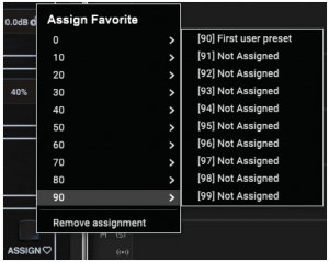
Creating your own presets will make them accessible from the Preset menu, but they will only appear in the list of 100 presets if you set them as a favorite. This isdone by assigning a favorite slot number to the preset using the Favorite menu. Recall one of your custom presets, then click the ASSIGN button and choose anavailable slot in one of the 10 banks. Some of the factory presets also reside in these banks, so you’ll have to work around them. When a preset is assigned a favorite slot number, that slot will be locked so that other presets cannot be assigned to the same location. This is shown in the Favorite menu by graying out the number in question. The favorite number will also be displayed in brackets next to the associated preset when you browse the presets menu. You can remove the favorite assignment by selecting the “Remove Assignment” feature in the Favorite menu, then saving the preset. Browse Favorites Only This option filters the user presets that are scrolled on the hardware unit so that only favorites are available. Make Current Preset Default Selecting ‘Make current preset default’ will cause this preset to appear every time a new instance of the plug-in is created. This function is disabled in Pro Tools. Reveal Presets Folder in Explorer To change the name of a preset, select ‘Reveal Presets Folder in Explorer’ and modify the file name. This will open a Finder (Mac) or Explorer (PC) window where the user presets are stored. You can rename as well as delete, copy and paste presets. This allows you to share presets with other users online, simply pasting the new ones in this folder. Downloaded Signature Presets from Newsletters or the TC Electronic website should also be put in this folder.
7. Software Updates
New versions of the software may be released to add new features and improve performance. Updates can be detected from the plug-in directly and can be installed after download from the website. See Chapter 2 for plug-in installation. If the ’Automatically check for updates’ option is checked inside the update menu, the red dot will appear on the settings icon when a new plug-in is available.
Click the gear icon and select “Check for Updates” to perform a scan.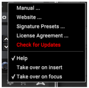
7.1 Hardware Unit Software Updates (optional)
The hardware unit firmware will be included in each plug-in update. After you have installed a new plug-in, the system will detect mismatched firmware and indicate a need for update via a small red dot on the gear icon. Click the “Upgrade to x.x.xx” field to start the update. Progress will be indicated in the plug-in.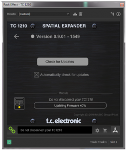

TC1210-DT
This equipment has been tested and found to comply with the limits for a Class B digital device, pursuant to part 15 of the FCC Rules. These limits are designedto provide reasonable protection against harmful interference in a residential nstallation. This equipment generates, uses and can radiate radio frequency energy and, if not installed and used in accordance with the instructions, may cause harmful interference to radio communications. However, there is no guarantee that interference will not occur in a particular installation. If this equipment does cause harmful interference to radio or television reception, which can be determined by turning the equipment off and on, the user is encouraged to try to correct the interference by one or more of the following measures:
- Reorient or relocate the receiving antenna
- Increase the separation between the equipment and receiver
- Connect the equipment into an outlet on a circuit different from that to which the receiver is connected
- Consult the dealer or an experienced radio/TV technician for help
This device complies with Part 15 of the FCC rules. Operation is subject to thefollowing two conditions:
- this device may not cause harmful interference, and
- this device must accept any interference received, including interference that may cause undesired operation
Important information:Changes or modifications to the equipment not expressly approved by Music Tribe can void the user’s authority to use the equipment.
Read More About This Manual & Download PDF:
References
[xyz-ips snippet=”download-snippet”]