![]()
![]() Professional High ReachJack Stand
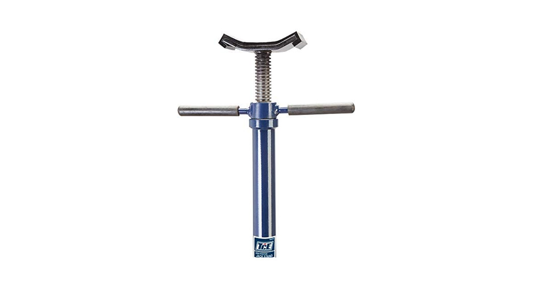
Professional High ReachJack Stand
![]() 1,500 lbs. LIFTING CAPACITYLifting Range : 53-9/16″ — 79-15/16″MODEL#TCE40753
1,500 lbs. LIFTING CAPACITYLifting Range : 53-9/16″ — 79-15/16″MODEL#TCE40753
![]() This is the safety alert symbol. It is used to alert you to potential personal injury hazards. Obey all safety messages that follow this symbol to avoid possible injury or death.
This is the safety alert symbol. It is used to alert you to potential personal injury hazards. Obey all safety messages that follow this symbol to avoid possible injury or death.![]() Questions, problems, missing parts? Before returning to your retailer, call our customer service department at 1-888-448-6746. 8 a.m.- 5 p.m.. PST. Monday-Friday.
Questions, problems, missing parts? Before returning to your retailer, call our customer service department at 1-888-448-6746. 8 a.m.- 5 p.m.. PST. Monday-Friday.
![]() SAFETY INFORMATIONSave these instructions. For your safety, read, understand, and follow the information provided with and on this product before using it. The owner and/or operator of this equipment shall have an understanding of safe use/operating procedures before attempting to use it. The owner and/or operator shall be aware that the use of this product may require special skills and knowledge. Instructions and safety information shall be conveyed in the operator’s native language before the use of this device is authorized. If any doubt exists as to the safe and proper use of this product as outlined in this factory authorized manual, remove it from service immediately.Inspect before each use. Do not use if broken, bent, cracked, or damaged parts (including labels) are noted. If the product appears damaged in any way, operates abnormally, or is missing parts, it should be removed from service immediately and the manufacturer notified. If you suspect that the product was subjected to a shock load (a load suddenly dropped unexpectedly upon it), immediately discontinue use until the product has been checked by a factory-authorized service center contact distributor or manufacturer for a list of Authorized Service Centers). It is recommended that an annual inspection be done by qualified personnel. Labels and owner’s manuals are available from the manufacturer.
SAFETY INFORMATIONSave these instructions. For your safety, read, understand, and follow the information provided with and on this product before using it. The owner and/or operator of this equipment shall have an understanding of safe use/operating procedures before attempting to use it. The owner and/or operator shall be aware that the use of this product may require special skills and knowledge. Instructions and safety information shall be conveyed in the operator’s native language before the use of this device is authorized. If any doubt exists as to the safe and proper use of this product as outlined in this factory authorized manual, remove it from service immediately.Inspect before each use. Do not use if broken, bent, cracked, or damaged parts (including labels) are noted. If the product appears damaged in any way, operates abnormally, or is missing parts, it should be removed from service immediately and the manufacturer notified. If you suspect that the product was subjected to a shock load (a load suddenly dropped unexpectedly upon it), immediately discontinue use until the product has been checked by a factory-authorized service center contact distributor or manufacturer for a list of Authorized Service Centers). It is recommended that an annual inspection be done by qualified personnel. Labels and owner’s manuals are available from the manufacturer.![]() WARNING!
WARNING!
- STUDY, UNDERSTAND AND FOLLOW ALL PRINTED MATERIALS PROVIDED WITH/ON THIS PRODUCT BEFORE USE.
- DO NOT EXCEED RATED CAPACITY.
- USE ONLY ON HARD, LEVEL SURFACES.
- CENTER LOAD ON SADDLE.
- DO NOT USE TO SUPPORT OR STABILIZE VEHICLE. THIS STAND IS INTENDED TO PROVIDE PARTIAL SUPPORT OF VEHICLE COMPONENTS DURING REMOVAL AND INSTALLATION.
- ADEQUATELY SUPPORT VEHICLE BEFORE STARTING REPOS.
- USE ONLY UNDER A PROPERLY SECURED AUTOMOTIVE LIFT.
- DO NOT USE ADAPTERS OR ACCESSORIES THAT ARE NOT PROVIDED INITIALLY.
- NO ALTERATIONS SHALL BE MADE TO THIS PRODUCT.
- FAILURE TO HEED THESE MARKINGS MAY RESULT IN PERSONAL INJURY AND/OR PROPERTY DAMAGE.
PRODUCT DESCRIPTIONThese stands are designed as a means of partial support for, and the positioning of, vehicle components during their installation/removal, but not for use in stabilizing or supporting vehicles.For use ONLY under a properly secured automotive lift.OPERATING INSTRUCTIONS This product should NEVER be used to lift or lower a vehicle. Do not lower the overhead lift in order to accommodate the stand. Contact with the desired vehicle component shall only be done by means of the vertical adjustments provided on the stand.To Raise
- Turn adjusting handle clockwise until saddle contacts load. Be sure to center load on saddle.
- On Model 3611, slight upward adjustments can be made to the saddle height by pressing downward on the foot pedal. This may or may not be necessary depending on the application. It is provided as a means of making temporary adjustments on load height without using your hands. This leaves your hands free to engage, handle and control the workpiece.
To LowerTo lower, simply turn the adjusting handle counter-clockwise.![]() Make certain that all personnel are clear of the load before lowering. Watch and control the rate of descent of the load at all times.
Make certain that all personnel are clear of the load before lowering. Watch and control the rate of descent of the load at all times.
ASSEMBLY DIAGRAM
 report this ad
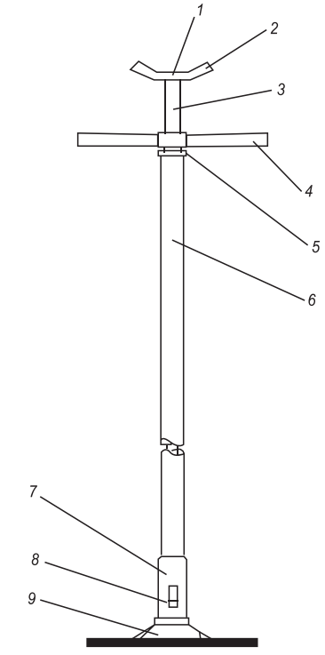
|
Part |
Description |
City |
| 1 | Rubber cap | 1 |
| 2 | Saddle | 1 |
| 3 | Screw | 1 |
| 4 | Adjusting Handle | 1 |
| 5 | Bearing | 1 |
| 6 | Columniation | 1 |
| 7 | Base connector | 1 |
| 8 | Pin | 1 |
| 9 | Base | 1 |
CARE AND MAINTENANCE
Periodically inspect each stand. Ensure all parts move freely. Do not apply oil or grease to any portion of this product II rust appears, sand affected area and cover with suitable utility paint. Please note that there is no replacement part applicable to this device.StorageThe store stands in an upright position and in a clean, dry area.
WARRANTY
ONE YEAR LIMITED WARRANTYFor a period of one year from the date of purchase. the manufacturer will repair or replace, at Its option, without charge, any of its products that fail due to a defect In material or workmanship. or which fail to conform to any implied warranty not excluded hereby.Performance of any obligation under this warranty may be obtained by returning the warranted product, Including dated purchase receipt, to the retailer or distributor where the product was purchased.For warranted service during the warranty period, the product must be returned to the retailer. Consumers should only submit products for repair directly to a warranty repair facility after the product warranty has expired. For the nearest approved Service Repair Facility, contact 1-888-448-6746, 8 a.m. — 5 p.m. PST. Monday — Friday.ALL WARRANTY SERVICES DURING THE WARRANTY PERIOD MUST BE HANDLED DIRECTLY THROUGH THE RETAILER.Except where such limitations and exclusions are specifically prohibited by applicable law, (1) the CONSUMER’S SOLE AND EXCLUSIVE REMEDY SHALL BE THE REPAIR OR REPLACEMENT OF DEFECTIVE PRODUCTS AS DESCRIBED ABOVE, and (2) THE MANUFACTURER SHALL NOT BE LIABLE FOR ANY CONSEQUENTIAL OR INCIDENTAL DAMAGE OR LOSS WHATSOEVER, and (3) THE DURATION OF ANY AND ALL EXPRESSED AND IMPLIED WARRANTIES. INCLUDING, WITHOUT LIMITATION, ANY WARRANTIES Cf MERCHANTABILITY AND FITNESS FOR A PARTICULAR PURPOSE, IS LIMITED TO A PERIOD OF ONE YEAR FROM DATE OF PURCHASE.This warranty gives you specific legal rights, and you may also have other rights which vary from state to state.
REPLACEMENT PARTS LIST
For replacement parts, call our customer service department at 1-888-448-6746, 8 a.m. – 5 pm., PST, Monday – Friday.Not all components of the jack are replacement items but are illustrated as a convenient reference of location and position in the assembly sequence.When ordering parts, give the model number, serial number, and description below.
[xyz-ips snippet=”download-snippet”]