![]()

RFID Access Card ReaderLA-5351 User Manual
DESCRIPTION AND FEATURES
Description
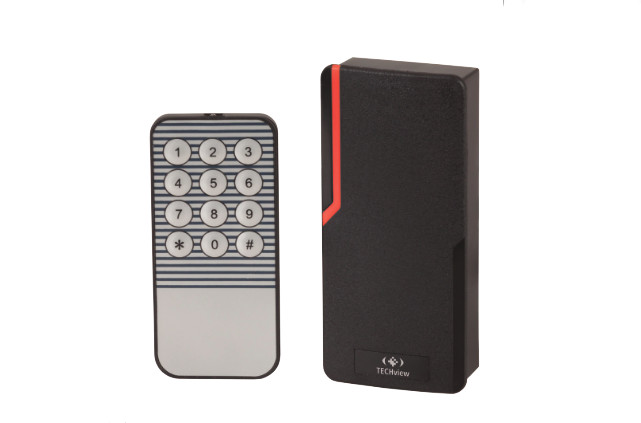
RFID Access Card Reader is fully waterproof standalone Proximity access control. It adopts the advanced MCU and large capacity Flash from Atmel, supporting up to 10000 cards. It is easy to add or delete card users by infrared remote keypad and master cards. It has the interfaces for external alarm, door contact, and exit button. They also have the functions of anti-passback.
Features
| Feature | Description |
| Card Type | EM & HID card |
| IP Grade | IP65 |
| Anti strong magnetism to open illegally | Field Effect Transistor control door |
| Large capacity | 10,000 card users |
| Wiegand input/output | Wiegand 26. Can work as controller or reader |
| Anti passback | One door or two doors anti-passback |
| Block enrollment | Can add 10,000 card users whose series number next to each other |
INSTALLATION AND WIRE INSTRUCTION
Installation
- Drill holes on the wall or prepare the cassette
- Wire through the hole, and blanket the unused cable in case of short circuit
- Fix the back cover firmly on the cassette or the wall
- Attach the machine to the back cover

Features
| Colour | Function | Description |
| Green | DO | Wiegand output, input signal wire DO |
| White | D1 | Wiegand output, input signal wire D1 |
| Grey | Alarm+ | Connecting to the negative pole of the alarm equipment |
| Yellow | OPEN | To connect to one part of Exit Button |
| Brown | D IN | Door Contact input |
| Red | 12V | (+) 12Vdc Positive Regulated Power Input |
| Black | GND | (-) Negative Regulated Power Input |
| Blue | VSS | The negative pole of the controller, connect to the other part of Exit button and door contact |
| Purple | L- | Connect to the negative pole of the Lock |
| Orange | L+/Alarm+ | Connect to the positive pole of the lock and alarm equipment |
Connection Diagram
There have 2 types of electronic lock in market, Factory default setting are Type B electronic lock, The lock time is 5 seconds.1. Type A electronic lock: Fail Secure lock (Unlock when power on), such as Electronic Controlling lock2. Type B electronic lock: Fail safe lock(Unlock when power off), such as EM lock, Electronic Bolt Lock, etc

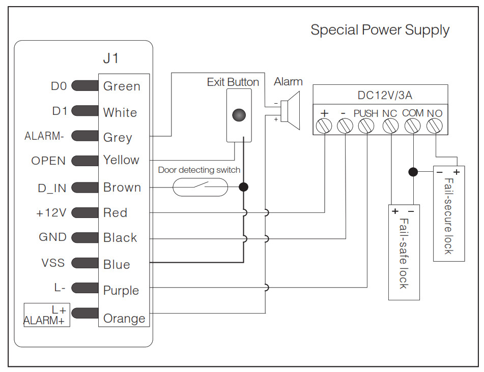
Note: Do not power on until all wiring has been completed
TO RESET TO FACTORY DEFAULT
Power off, use the supplied Contact Pinto short out the 2P socket on the mainboard, then power on, if successful, the beeper will beep twice, the LED shines in orange, remove the Short Pin, then read the Two Manager cards (Manager add card firstly, Manager delete card secondly), after that the LED turns in red, means reset to factory default setting successfully. Remarks: Reset to the factory default setting, the users’ information enrolled is still retained. When re-set to Factory setting, the two Manager cards must be re-enrolled.
USE MANAGER CARD
4.1 To add user by Manager CardRead Manager add card Read user card Read Manager card Quit add user mode4.2 To delete user by Manager cardRead Manager delete card Read user card Read Manager card Quit add user mode Note: Users can be added or deleted continuously
MASTER OPERATION ( BY REMOTE CONTROL)
Enter the programming mode *888888# .888888 is the default factory master codeNote: the following operation with “5” title, must enter into the programming mode. # means confirm, Last # means end current setting situation. * means quit5.1 Change the master codeCode must be 6-8 digits numbers. please keep it5.2 Add user5.2.1 To read card continuously 1 read user card #5.2.2 To input card number continuously 1 8digits card number #5.2.3 To add series card number 8 8digits card number # card quantity # Card quantity is between 1-9999 It takes 45minutes to add 9999 cards. During the time, the green light blinks5.3 Delete user5.3.1 Delete card by reading continuously 2 read card #5.3.2 Delete card by inputing card number continuously 2 8digits card number #5.3.3 Delete all 2 0000# This option will delete all users but manager cards. Be careful when using.5.4 Anti-passback setting5.4.1 Anti-passback disabled (Factory default) 3 0 #5.4.2 Anti-passback master mode 3 1 #5.4.3 Anti-passback Auxiliary mode 3 2 #Note: The detailed wiring diagram and illustration, please refer to the “Advanced application”5.5 Lock power setting5.5.1 Fail secure (Unlocked when power on) 4 0-99 # is to set the door relay time.0s=50ms5.5.2 Fail safe (Unlocked when power is off ) 5 1-99 #5.6 Door open detection5.6.1 To disable door open detection 6 0 #5.6.2 To enable door open detection 6 1 #When this function is enabled, there are two situations1. If the door is opened normally, but not closed after 1 minute, the inside buzzer will beep automatically to remind people to close the door. Close the door or read user card can stop the beep2. Push the door after it is opened in 120minutes by legal way; or the door is forced open, the external alarm system and Buzzer built-in controller will give alarm sound5.7 Secure mode and LED light setting5.7.1 Secure mode setting5.7.1.1 Normal mode: 7 0 # No lockout or alarm, and it is factory default setting.5.7.1.2 Lockout mode: 7 1 # The machine will lockout for 10 minutes if we swipe 10 times invalid card in 10 minutes.5.7.1..3 Alarm mode: 7 2 # External alarm system and Buzzer built-in controller will give alarm sound in the same time when we swipe 10 times invalid card in 10 minutes.5.7.2 LED light setting5.7.2.1 RED LED ON(factory default setting): 7 3 # 5.7.2.2 RED LED OFF: 7 4 #5.8 Time of alarm setting5.8 0-3 #Alarm time: 0-3 minutes, default setting is 1minute
OPERATION OF OPENING THE DOOR
Open the door by swiping valid card.
DISALERT ALAM OPERATION
Three ways: swiping user card, manager card, input manager’s PIN.
SOUND AND LED LIGHT INDICATION
| Operation Status | Colour of LED | Sound of Buzzer |
| Stand by Status | Slow RED flash | |
| Press key of remote control | Bee-eep | |
| Enter into programming | RED on | Bee-eep |
| Enter into setting | ORANGE on | Beep |
| Error | Beep, Beep, Beep | |
| Open the door | GREEN | Bee-eep |
| Alarm | Quick RED flash | Alarm Sound |
TECHNICAL PARAMETERS
| Working Voltage | DC12V±10°/0 |
| Stand by Current | <15mA |
| Swiping Distance | 3-8cm |
| Operating Temperature | -40°C |
| Operating Humidity | 0-95% RH |
| Max Current of lock output load | 3A |
| Max Current of alarm output load | 3A |
| Manager card (EM card) | One add card, one delete card |
| Dimension | 103 x 48 x 23mm |
PACKING LIST
| Name | Quantity | Remark |
| Waterproof Reader | 1 | |
| Infrared Remote Control | 1 | |
| Manager Add Card | 1 | |
| Manager Delete Card | 1 | |
| Short Pin | 1 | Used for factory default setting |
| User Manual | 1 | |
| Self Tapping Screws | 4/2 | 3.5(Dia.) x 27mm |
ADVANCED APPLICATION
Operating as a Wiegand output reader.

Figure 4
Diagram of output reader and anti-passback for single door.
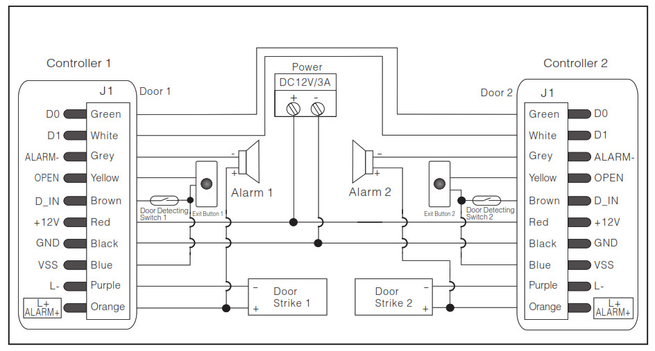
11.2 Anti-passback function for the single door (Set as function 5. 4.2) The connection diagram is as figure 4. Install one Wiegand reader (without user information as reader) outside the door, connecting to one Controller inside the door, which acts as the Anti-passback Master unit of the two devices, they build up an Anti-passback system for single door.The operation function is as below:11.3 Set the needed function and enroll the User Cards on the inside Anti-passback Master unit.11.4 With the valid user card, the user can only enter the door from the outside reader, and exit from the inside Controller. On the other hand, without entering record from the reader, the user can’t exit from the controller inside, also, the user can’t enter in twice without the first exit record , and vice versa.11.5 Anti-passback function for 2 doors (Set as function 5.4.2) The connection diagram is as Figure 5. Door 1 with one Card Reader, and Door 2 with one Card Reader, set one Card Reader on Door 1 as the Anti-passback Auxiliary unit, and set the other Card Reader on Door 2 as the Anti-passback Master unit. They build up a two doors Anti-passback system, which is normally used for parking lot etc.
The operation function is as below:11.6 Set the needed function and enroll the User Cards from the Anti-passback Master unit on Door 2.11.7 With the valid user card, the user can only enter in from Door 1, and exit from Door 2. On the other hand, without entering record from the Auxiliary unit, the user can’t exit from the Master unit or Auxiliary unit, also, the user can’t enter in twice without the first exit record, and vice versa
| Colour | Function | Description |
| Green | DO | Wiegand output, input signal wire DO |
| White | D1 | Wiegand output, input signal wire D1 |
| Grey | Alarm+ | Connecting to the negative pole of the alarm equipment |
| Yellow | OPEN | To connect to one part of Exit Button |
| Brown | D_IN | Door Contact input |
| Red | 12V | (+) 12Vdc Positive Regulated Power Input |
| Black | GND | (-) Negative Regulated Power Input |
| Blue | VSS | The negative pole of the controller, connect to the other part of Exit button and door contact |
| Purple | L- | Connect to the negative pole of the Lock |
| Orange | L+/Alarm+ | Connect to the positive pole of the lock and alarm equipment |
Distributed by: TechBrands by Electus Distribution Pty. Ltd.320 Victoria Rd, RydalmereNSW 2116 AustraliaPh: 1300 738 555Intl: +61 2 8832 3200Fax: 1300 738 500www.techbrands.comMade in China
[xyz-ips snippet=”download-snippet”]