Ultra-low Power Consumption Bluetooth 4.2 BLE ModuleJDY-19 Bluetooth Module Usage Manual
JDY-19 Ultra-low Power Consumption Bluetooth 4.2 ModuleVersion
| Version | Date | Description |
| V1.2 | 2018-03-03 | Release version |
| V1.3 | 2018-05-20 | The feature FFE2 function iscancelled |
JDY-19 Ultra-low Power Consumption Bluetooth 4.2 Module
Product introduction
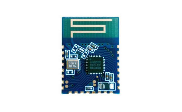
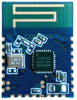
JDY-19 transparent transmission module is based on the Bluetooth 4.2 protocol standard, the frequency range is 2.4GHZ, the modulation mode is GFSK, the maximum transmission power is 4dB, the maximum launch distance is 40 meters. The imported original chip is designed to support the user to modify the device name, baud rate and so on through the AT command, which is convenient, quick and flexible to use.JDY-19 Bluetooth module can realize data transmission between module and cell phone, or module and module, and can quickly use BLE Bluetooth for product application through simple configuration.
Let BLE be more quick and convenient in product application
 Debug tool
 Debug tool
2.1:APP tool(IOS and Android share one two-dimensional code)

Scan with WeChat and select in the upper right corner to open it in the browser2.2 Serial port tool (Packet incidental)

Module parameter details
3.1 Module parameters
| JDY-19 product parameters | |
| Model | 113Y-19 |
| Frequency Range | 2.4G |
| Transmitting power | 4db (MAX ) |
| Communication interface | UART |
| Working voltage | I.8V — 3.6V |
| Working temperature | -40r – 80r |
| Antenna | Built-in PCB antenna |
| Reception sensitivity | -97dbm |
| Transmission distance | 80 meters |
| Master-slave support | Slave machine |
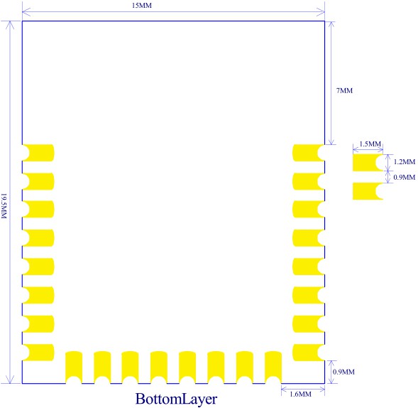
| Module size | 19.6′ 14.94 * 1.8 mm ( Length. width and height ) |
| Bluetooth version | BLE 4.2 (compatible BLE4.0.. BLE4.I ) |
| Wake-up status current | 500uA ( Broadcast ) |
| Shallow sleep status current | <50uA (Broadcast) |
| Deep sleep current | 3uA ( No broadcast ) |
| Instruction parameterpreservation | Parameter configuration of power down data is saved |
| STM welding temperature | <260’C |
Working current
| Working mode | Status | Averagecurrent | Remarks |
| Wake up serialporttransparenttransmission | Unconnected | 500u.\ | General communicationwith APP, it isrecommended that the broadcasting should not be set too long, for which will affect the connection time. It is generally recommended between 100 and 500mS. If it needs fastconnection with norequirement of powerconsumption. you can set the broadcast interval to the shortest. |
| Deep sleepwithoutbroadcast | No broadcast | 3uA | |
| Light sleep withbroadcast | 100mS Broadcastinterval | 200uA | |
| .%. era ye powerconsumption | 200mS Broadcastinterval | 80uA | |
| 300mS Broadcastinterval | 30uA | ||
| 400mS Broadcastinterval | The followingcurrent islower | ||
| In the connected state, you |
| Wake uptransparent | Connected | 900uA | can lower the PWRC pin tosend the AT instruction or |
| transmission | set the working mode | ||
| status | directly. See the | ||
| AT+STARTEN instructionfor details. |
All working mode currents are not more than IMA (Including the current at the time of transparent transmission through the serial port).3.3 JDY-19 sleep mode introduction
| ship mode | Instructions | Function Introduction |
| shut | AT+STARTEN I | Mode I: Start wake-up, users need sleep can be |
| wake-up | controlled by AT+SLEEP command, wake up can be awakened by PWRC pin low level. | |
| Mode 0: Under this mode, the power consumption IS | ||
| S tart sleep | AT-S FARTENO | very low, the connection wake-up transparenttransmission current is 900uA, and the disconnect current is below 200uA (the broadcast interval current can be set to 30uA). After the PWRC pin wake-up under this mode, if the serial port does not send data in 10 seconds or not to be connected, it will turn into sleep again automatically. |
3.4 Frequently asked questions
| Questions | Answers |
| I : How MCU disconnects theBluetooth connection in theconnection state? | In the connection state, lower the PWRC pin, and the serial port sends AT+DISC to disconnect. |
| 2:How much is the current when the module wakes up? | All modes’ working current Is not more than 1 mA. |
| 3:How many data can be written to the serial port once? | No byte limit at 9600 baud rate |
| 4:After the serial port is configured, is it need to restart to take effect? | It is recommended to restart the module when the parameters are set |
| 5:How to test the deep sleep current of the test module? | VCC and GND pins are recommended for testing current. |
3.5 Factory commonly used default parameter configuration
| Sequence | Function | Factory defaultparameters | Instructions |
| I | Serial port baud rate | 9600 | AT+BAUD4 |
| 2 | Sleep mode | Start wake-up | AT+STARTENI |
| 3 | Broadcast name | JDY-19 | AT+NAMEJDY-19 |
| 4 | Broadcast interval | 200MS | AT+ADVINI |
The above is a serial port transparent transmission communication function. If you need special functions, you can contact JDY to technique support. QQ:3411947569
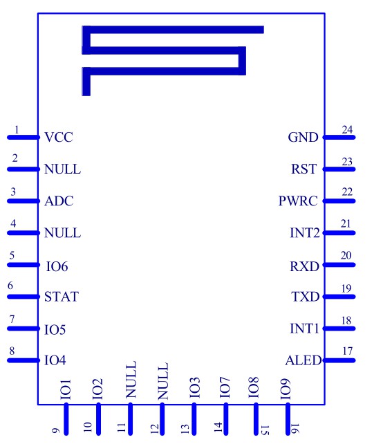
3.6 Pin definition
3.7 Pin function introduction
| Pins | Function | Introduction |
| 1 | VCC | Power supply (1.8-3.6V) |
| 2 | NULL | None |
| 3 | ADC | ADC pin |
| 4 | NULL | None |
| 5 | 106 | GPIO or PWM 1 |
| 6 | STAT | Connect status pin, which has been connected to high level. unconnected to low level |
| 7 | 105 | GPIO or PWM2 |
| 8 | 104 | GPIO or PWM3 |
| 9 | 101 | GPIO or PWM4 |
| 10 | 102 | GPIO |
| 11 | NULL | None |
| 12 | NULL | None |
| 13 | 103 | GPIO |
| 14 | 107 | GPIO |
| 15 | 108 | GPIO |
| 16 | 109 | GPIO |
| 17 | ALED | Broadcast indicator pin |
| 18 | INT1 | Button interrupts the input pin (key-value is uploaded to APP) |
| 19 | TXD | Serial port output pin (TTL level) |
| 20 | RXD | Serial port input pin (TTL level) |
| 21 | INT2 | Button interrupts the input pin (key-value is uploaded to .\ PP ) |
| 22 | PWRC | Sleep wake-up pin, low level effectiveUnder connection state, the AT instruction can be sent through lower the PWRC pin, such as AT+DISC disconnect. |
| 23 | RST | Soft reset pin, low level effective |
| 24 | GND | Power ground |
3.8 PCB package size
Serial port AT instruction set
JDY-19 module sends the AT instruction must end with the \r\n
| Sequence | Instructions | Function | Master /slave | Workingmode | Default |
| 1 | AT+VER | Version number | JDY-19-V1.2 | ||
| 2 | AT+RST | soft reset | |||
| 3 | AT+DISC | AT instructiondisconnect | |||
| 4 | AT+MAC | MAC address | |||
| 5 | AT+BAUD | baud rate | 9600 | ||
| 6 | AT+BOUD | baud rate | 9600 | ||
| 7 | AT+SLEEP | sleep | |||
| 8 | AT+NAME | broadcast name | JDY-19 | ||
| 9 | AT+START EN | Start sleep or wakc up | 0 (start wake up | ||
| 10 | AT+ADVIN | broadcast interval | I (200mS | ||
| 11 | AT+HOSTE N | slave mode orIBEACON workingmode | 0 (slave | ||
| 12 | AT+IBUUI D | IBEACON DJ UUID | FDA50693A4E24FB I AFCFC6EB076478 25 | ||
| 13 | AT+MAJO R | IBEACON MAJOR | 10 | ||
| 14 | AT+MINO R | BEACON MINOR | 7 | ||
| 15 | AT+IBPWR | The SING value of IBEACON | 50 | ||
| 16 | AT+DEFAU LT | Restore factorysettings |
Introduction:Green text indicates new functions, The red bold part needs special attention.
AT instruction introductions
Special description: JDY-19 module serial AT instructions need to end with \r\nQuery – version number
| Instruction | Response | Parameter |
| AT+VER | +VER:JDY-19-V1.2 | None |
Setup – soft reset
| Instruction | Response | Parameter |
| AT+RST | OK | None |
Set up – disconnect
| Instruction | Response | Parameter |
| AT+DISC | OK | None |
Note: Under connection state, the PWRC pin needs to be pulled down to send AT instructions in the connection state.Setup/query – MAC addresses
| Instruction | Response | Parameter |
| AT+MAC | +MAC=<Param> |
Setup/query – baud rate
| Instruction | Response | Parameter |
| AT+BAUD<Param> | OK | Param: (1-9) |
| 0-11520 | ||
| 1-57600 | ||
| 2-38400 | ||
| AT+BAUD | +BAUD=<Param> | 3-19200 |
| 4-9600 | ||
| 5-4800 | ||
| 6-2400 | ||
| Default value: 4 |
Setup/query – sleep instruction
| Instruction | Response | Parameter |
| AT+SLEEP<Param> | +SLEEP:OK | Param: (1-2)1:Light sleep (Broadcast)2:Deep sleep (No broadcast) |
| AT+SLEEP |
AT+STARTEN0 state does not need to send AT+SLEEP instructions, modules automatically enter sleep. After the mobile phone is connected, it will wake up automatically, if disconnecting the connection it will automatically turn into sleep. PWRC pin low level wake-up, it will automatically go to sleep if the serial port has no data transmission, or no connection after wake up 10 seconds later.
Setup/query –broadcast name
| Instruction | Response | Parameter |
| AT+NAME<Param> | OK | Param: Module Bluetooth nameThe longest: 18 bytesDefault name: JDY-I9 |
| AT+NAME | +NAME=<Param> |
Setup/query – start sleep and wake-up read & write
| Instruction | Response | Parameter |
| AT+STARTEN<Param> | OK | Param: (0-2)1: Start wake up, sleep can be controlled by AT+SLEEP0: Start sleep, connect to wake-up,disconnect to connect sleep |
| AT+STARTEN | +STARTEN=<Param> |
Setup/query – broadcast interval
| Instruction | Response | Parameter |
| Param: (0-9) | ||
| 0-100ms | ||
| AT+ADVIN<Param> | OK | I-200ms |
| 2-300ms | ||
| 3-500ms | ||
| 4-500ms | ||
| 5-600ms | ||
| 6-700ms | ||
| 7—SOOms | ||
| 8-900ms | ||
| 9-1000ms | ||
| Default value: 0 |
Setup/query – Module working mode
| Instruction | Response | Parameter |
| AT+HOSTEN<Param> | OK | Param: (0-3)0—Slave ( APP, WeChat smallprogram) transparent transmission3—Slave ( iBeacon) modeDefault value: 0 |
| AT+HOSTEN | +HOSTEN=<Param> |
Setup/query – iBeacon UUID
| Instruction | Response | Parameter |
| AT+IBUUID<Param> | OK | Param: Hexadecimal UUID Default value:FDA50693A4E24FB I AFCFC6EB07647825 |
| AT+IBUUID | +IBUUIDParam> |
Example:AT+IBUUID FDA50693A4E24FB1AFCFC6EB07647825Setup/query – iBeacon Major
| Instruction | Response | Parameter |
| AT+MAJOR<Param> | OK | Param: (0000-FFFF) Default: 000A |
| AT+MAJOR | + MAJOR=<Param> |
If the Major value is 10008, the AT instruction is: AT+MAJOR2718 2718 is 10008 hexadecimal data.Setup/query – iBeacon Minor
| Instruction | Response | Parameter |
| AT+MINOR<Param> | OK | Param: (0000-FFFF) Default: 0007 |
| AT+MINOR | +MINOR=<Param> |
If the Minor value is 10180, the AT instruction is: AT+MINOR27C4 27C4 is 10180 hexadecimal data.Setup/query – iBeacon IBSING
| Instruction | Response | Parameter |
| AT+IBSING<Param> | OK | Param: (00-FF ) Default: 40 |
| AT+IBSING | +IBSING —cParam> |
This parameter is applied to the 1 meter iBeacon signal check value
Restore factory configuration (revert to factory default configuration parameters)
| Instruction | Response | Parameter |
| AT+DEFAULT | +OK | None |
Mobile phone end instruction
6.1 APP UUID listService UUID:FFE0 (Service UUID Default ffe0)Feature UUID:FFE1 (Use for transparent transmission Default ffe1)
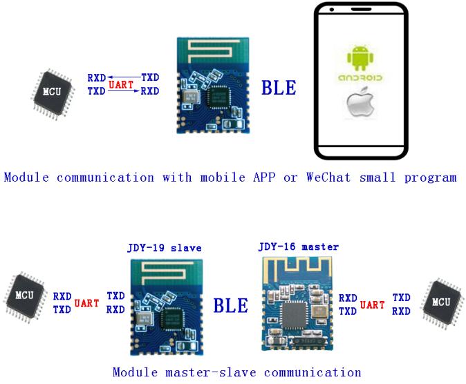
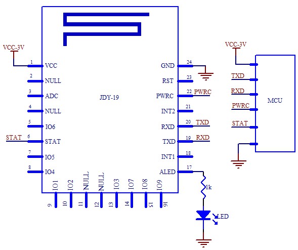
JDY-19 Basic application wiring diagram
7.1 Serial port communication mode wiring diagram
[xyz-ips snippet=”download-snippet”]