tekmar Invita WiFi Thermostat User Manual
For Use With
Conventional systems
- Up to 2-stage heating, 2-stage cooling, fan and 2 accessories
Heat pump & dual fuel systems
- Up to 4-stage heating, 2-stage cooling, fan, reversing valve and 1 accessory
Accessory options
- Humidifier, dehumidifier, HRV/ERV ventilator
Need more information?
- User Brochure 564_U includes detailed information on using the thermostat and app
- Quick Setup Guide 564_Q is available from: tekmarcontrols.com/Invita
Scan to open Invita webpage ![]()
![]()
Product Overview
This Operation Manual provides in-depth operation and troubleshooting details. Additional literature including a Quick Setup Guide and User Brochure are available from tekmarcontrols.com/Invita. The Quick Setup Guide 564_Q provides details on installation and wiring. The User Brochure 564_U includes details on setting up the Invita Connect app, WiFi connections and other adjustments a homeowner would typically make when using the thermostat. For assistance, contact your local tekmar representative: www.tekmarcontrols.com/company/contact representative.html. Or call tekmar customer service at 1-800-438-3903.
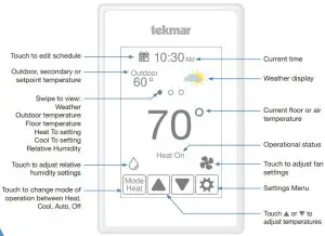
Heating and Cooling Operation
- The Heat On symbol is shown on the display when the thermostat is heating.
- Heating for freeze protection is provided whenever the air or floor temperature falls below 40°F (4.5°C), regardless of operating mode.
- The Cool On symbol is shown on the display when the thermostat is cooling.
The thermostat supports two heating system types: 1) conventional, or 2) heat pump.
Conventional Systems
A conventional heating system includes: furnaces, air conditioners, hydronic heating systems with baseboards, radiant floors, or fan coils and electric heating.The thermostat supports up to two heating stages, two cooling stages, a fan and two accessory relays.
|
Equipment Setting |
1H/1C | 1H/2C | 2H/1C | 2H/2C |
| First stage heating | W1 | W1 | W1 |
W1 |
|
Second stage heating |
– | – | W2 | W2 |
| First stage cooling | Y1 | Y1 | Y1 |
Y1 |
|
Second stage cooling |
– | Y2 | – | Y2 |
| Fan |
G |
|||
|
Accessory 1 |
Choice of: Humidifier, Dehumidifier, HRV/ERV | |||
| Accessory 2 |
Choice of: Humidifier, Dehumidifier |
Heat Pump Systems
A heat pump system may include additional heat sources as backup. The thermostat supports up to four heating stages, two cooling stages, a reversing valve, a fan and one accessory relay.
|
Equipment Setting |
1HP | 1HP/
1Aux |
1HP/
2Aux |
2HP | 2HP/
1Aux |
2HP/
2Aux |
| First stage heating | Y1 | Y1 | Y1 | Y1 | Y1 |
Y1 |
|
Second stage heating |
– | W1 | W1 | Y2 | Y2 | Y2 |
| Third stage heating | – | – | W2 | – | W1 |
W1 |
|
Fourth stage heating |
– | – | – | – | – | W2 |
| First stage cooling | Y1 | Y1 | Y1 | Y1 | Y1 |
Y1 |
|
Second stage cooling |
– | – | – | Y2 | Y2 | Y2 |
| Fan |
G |
|||||
|
Accessory 1 |
Choice of: Humidifier, Dehumidifier, HRV/ ERV ventilator | |||||
| Accessory 2 |
Reversing valve O relay remains closed during cooling. Reversing valve B relay remains closed during heating. |
When radiant floor heating is installed, it is always the first stage of heating, followed by the heat pump, and lastly any backup heating. This allows the floor to remain warm in the heating season.
|
Equipment Setting |
1HP | 1HP/
1Aux |
1HP/
2Aux |
2HP | 2HP/
1Aux |
2HP/
2Aux |
| First stage heating | Y1 | W1 | W1 | Y1 | W1 |
W1 |
|
Second stage heating |
– | Y1 | Y1 | Y2 | Y1 | Y1 |
| Third stage heating | – | – | W2 | – | Y2 |
Y2 |
|
Fourth stage heating |
– | – | – | – | – | W2 |
|
First stage cooling |
Y1 | Y1 | Y1 | Y1 | Y1 | Y1 |
| Second stage cooling | – | – | – | Y2 | Y2 |
Y2 |
|
Fan |
G | |||||
| Accessory 1 | Choice of: Humidifier, Dehumidifier, HRV/ERV ventilator | |||||
| Accessory 2 |
Reversing valve O or B. O relay remains closed during heating operation. B relay remains closed during cooling operation. |
Heating Differentials
The first stage heat turns on when the air temperature falls 1.5°F (1°C) below the Heat To setting and shuts off when the air temperature reaches the Heat To setting.The second, third and fourth stage heat each have an adjustable differential and time delay setting to determine when the stage turns on, and shut off when they reach 1.5, 1.0, and 0.5°F (0.75, 0.5, and 0.25°C) of the Heat To setting respectively
Radiant Floor HeatingRadiant floor heating is operated differently than other heating types due to the large time delays to heat and cool the slab.When Radiant Floor Heating is selected in the setup menu, the W1 relay operates using Pulse Width Modulation. This improves comfort for radiant systems with high mass floors.
- 100% on time at Heat To setting -1.5°F
- 50% on time at Heat To setting
- 0% on time at Heat To setting + 1.5°F
When a radiant floor has a second stage of heat, the second stage turns on when all of these conditions are met:
- The first stage is on at 100%
- The ambient air temperature falls below the Heat 2 Differential
- The Heat 2 Delay has elapsed
Room Sensor and AveragingThe room tempartaure can be measured using a combination of the built-in and auxillary sensors.
- Built-in room sensor only
- Built-in room sensor with auxiliary rooom sensor(s) (temperature is averaged)
- Auxiliary room sensor only
Floor Sensor for Radiant Floor HeatingIf a floor sensor is connected, floor minimum and maximum settings are available.For a combination of air and floor temperature control, leave the internal air sensor on in the setup menu. A floor minimum can be used to prevent a fast drop in temperature caused by receding solar exposure. This operation is recommended for areas heated by afternoon sun through large windows. When the sun sets, it can take a long time for the floors to get warm again. This may cause the room to cool off too much in the early evening. A floor minimum setting can help with this condition by maintaining a floor minimum temperature. Keep in mind the floor minimum temperature will override the air temperature, and if set too high, may overheat the room.A floor maximum is recommended for rooms with hardwood floors. Setting floor minimum and maximum temperatures is a way of enhancing the comfort of the living space while protecting floor coverings.If there are more than one floor temperature sensors, the temperature is averaged.
Cooling DifferentialsThe first stage cooling turns on when the air temperature rises 1.5°F (1°C) above the Cool To setting and shuts off when the air temperature reaches the Cool To setting.The second stage cooling has an adjustable differential and time delay setting to determine when the stage turns on, and shuts off when it reaches 0.5°F (0.25°C) above the Cool To setting.
Heat Pump Balance PointAn air source heat pump’s Coefficient of Performance (COP) declines with falling outdoor air temperature. The Balance Point is the outdoor temperature at which it is more economical to shut off the heat pump (relays Y1 and Y2) and operate the backup heating equipment (relays W1 and W2).
Dual FuelDual fuel systems include a heat pump together with a backup heat source such as a furnace or a hydronic fan coil. When Dual Fuel is set to on, the heat pump (relays Y1 and Y2) is shut off whenever the backup heating equipment (relays W1 and W2) is operating.
Warm Weather Shut Down (WWSD)The heating system can automatically shut off based upon the outdoor temperature and the WWSD setting. This provides a convenient way to shut off radiant floor heating.Cold Weather Shut Down (CWSD)The cooling system can automatically shut off based upon the outdoor temperature and CWSD setting. This prevents unwanted cooling during the winter.
Relative Humidity Operation
Relative Humidity SensorThe thermostat includes an internal relative humidity (RH) sensor and has the option to connect to an external RH sensor. The installer has the option to disable the internal RH sensor when an external RH sensor is installed. When both the internal and external RH sensors are enabled, the RH reading is averaged.
Humidifier OperationThe thermostat controls the relative humidity (RH) by operating either the Accessory 1 or Accessory 2 relays.This is an installer configurable setting. When the RH is below the Humidify To setting by 3%, the Accessory 1 or 2 relay is closed to operate a humidifier. The humidifier is shut off when the RH reaches the Humidify To setting.The thermostat can operate 3 types of humidifiers:
Stand Alone
- The humidifier is not connected to the HVAC system.
- The thermostat Mode can be set to Heat, Cool, Auto or Off.
Steam
- The steam humidifier is ducted to the HVAC system.
- The thermostat Mode can be set to Heat, Cool, Auto or Off.
- Requires the system fan to turn on when operating.
Evaporative
- A drum style humidifier which requires the heating system to operate to evaporate the water.
- This system requires the system fan to operate.
- The thermostat Mode must be set to Heat or Auto.
Humidifier Window ProtectionDuring cold weather, condensation will form on windows when the relative humidity (RH) is too high. The optional window protection feature automatically calculates the indoor dew point based upon the outdoor temperature and the quality of the windows installed. The humidifier is then operated to the highest possible RH that is below the Humidify To setting.
Dehumidifier OperationThe thermostat controls the relative humidity (RH) by operating either the Accessory 1 or Accessory 2 relay. This is an installer configurable setting. When the RH is above the Dehumidify To setting by 3%, the Accessory 1 or 2 relay is closed to operate the dehumidifier. The dehumidifier is shut off when the RH reaches the Dehumidify To setting.The thermostat can operate 2 types of dehumidifiers:
Stand Alone
- The dehumidifier is not connected to the HVAC system.
- The thermostat Mode can be set to Heat, Cool, Auto or Off.
DX Coil
- The HVAC cooling system is used for dehumidification.
- The Accessory 1 or Accessory 2 relay activates the DHUM operation on the air handling unit to operate the system fan at low speed.
- The cooling compressor Y1 and Y2 relays are operated. The chilled DX coil condenses moisture from the air.
- The cooling system can over cool the room temperature by 2°F (1°C) during dehumidification.
HRV / ERV Ventilator Operation
Ventilation with fresh outdoor air is important for maintaining indoor air quality. The thermostat can operate a heat recovery ventilator (HRV) or energy recovery ventilator (ERV) on a timer by closing the Accessory 1 relay to operate the ventilator fan at low speed.
Heat Pump Loop Valve Operation
The thermostat supports water-to-air heat pump systems that absorb or reject heat to a hydronic building loop.Whenever the heat pump compressor Y1 or Y2 relay is turned on, the Accessory 1 relay closes to open a hydronic zone valve. This allows variable speed pumps on the hydronic loop to operate at lower speeds when the heat pump is off, thereby saving electrical energy.
Invita™ WiFi Thermostat Settings
Display
|
Setting |
Range | Default |
| TEMPERATURE UNITS
Select °F or °C. |
°F or °C |
°F |
|
ENERGY USE View the number of hours the heating or cooling has operated either daily or monthly. |
0 to 24 (daily) 0 to 744
(monthly) |
0 hours |
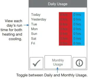
Toggle between Daily and Monthly Usage.
|
Setting |
Range | Default |
| BRIGHTNESS ACTIVE
Select the brightness when touching the screen. |
30 to 100% |
100% |
|
BRIGHTNESS INACTIVE Select the brightness when not in use. |
Off, 30 to
100% |
50% |
|
BACKGROUND Select the background color. |
Light, Blue, Night, Latte, Espresso |
Blue |
|
LANGUAGE Select the language. |
English, Español, Français |
English |
| SCREEN CLEAN
Locks screen for 10 seconds to allow cleaning. |
N/A |
N/A |
|
INACTIVE TIME DISPLAY Select if the time is visible when the display is inactive. |
Off or On |
On |
| INACTIVE HUMIDITY DISPLAY
Select if the humidity is visible when the display is inactive. |
Off or On |
Off |
|
INACTIVE OUTDOOR DISPLAY Select if the outdoor temperature is visible when the display is inactive. |
Off or On |
Off |
TimeWhen connected to the Internet, the time can be set automatically.
Notices
Incorrectly setting the time and date manually may prevent the thermostat from communicating to the mobile app. Automatic time source is recommended when using an Internet connection.
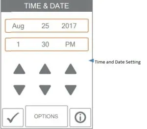
The time and date can be manually set by highlighting a field and then using the or buttons.
The options listed below are available by pressing the “Options” button on the screen.
|
Setting |
Range | Default |
|
TIME FORMAT Select the time format. |
12 or 24 hour |
12 hour |
| TIME SOURCE
If Internet is available, the time source can be either automatically or manually set. |
Automatic, Manual |
Auto |
|
TIME ZONE Select the local time zone. |
Hawaii, Alaska, Pacific, Mountain, Central, Eastern, Atlantic, Newfoundland |
Eastern |
| DAYLIGHT SAVING TIME
Set to On if daylight savings time applies to installation location. |
Off, On |
On |
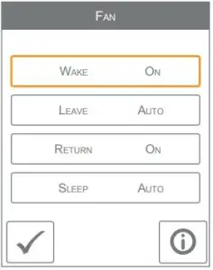
Fan
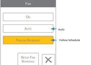
The fan is normally off when set to auto but turns on when needed for the heating or cooling equipment.When a programmable schedule is used, there is a fan setting for each time period.
Setup – Toolbox
| Setting | Range |
Default |
|
ERROR Displays any error messages. |
N/A | N/A |
| ACCESS LEVEL
Select between user and installer access levels. User access level restricts access in the Setup Menu. |
User, Installer |
Installer |
|
STATUS The current status of warm weather shut down, cold weather shut down and each of the relays. |
Early Start, WWSD, CWSD, W1,
W2, Y1, Y2, G, Acc1, Acc2 |
N/A |
| SOFTWARE VERSION
Display the software version. |
J1266A |
N/A |
|
LOAD DEFAULTS All settings are returned to factory defaults. |
Yes, No |
No |
| CALIBRATE TOUCHSCREEN
Recalibrate the screen after loading factory defaults. |
N/A |
N/A |
Setup – Temp
| Setting | Range | Default |
| Screen Page 1 | ||
| HEAT TO AWAY
Select the heating temperature when away. |
Off, 40 to 100°F Off, 4.5 to 38.0°C | 62°F
16.5°C |
| HEAT TO MIN LIMIT
Select the minimum heating temperature limit. |
Off, 40 to 95°F Off, 4.5 to 35.0°C |
Off |
| HEAT TO MAX LIMIT
Select the maximum heating temperature limit. |
Off, 40 to 95°F Off, 4.5 to 35.0°C |
Off |
| COOL TO AWAY
Select the cooling temperature when away. |
Off, 40 to 100°F Off, 4.5 to 38.0°C |
Off |
| COOL TO MIN LIMIT
Select the minimum cooling temperature limit. |
Off, 40 to 100°F Off, 4.5 to 38.0°C |
Off |
| COOL TO MAX LIMIT
Select the maximum cooling temperature limit. |
Off, 40 to 100°F Off, 4.5 to 38.0°C |
Off |
| Screen Page 2 | ||
| FLOOR MIN – WAKE
Select the floor temperature while in the wake schedule. Applies when there is both a floor and an air sensor. |
Off, 40 to 95°F Off, 4.5 to 35.0°C |
Off |
| FLOOR MIN – LEAVE
Select the floor temperature while in the leave schedule. Applies when there is both a floor and an air sensor. |
Off, 40 to 95°F Off, 4.5 to 35.0°C |
Off |
| FLOOR MIN – RETURN
Select the floor temperature while in the return schedule. Applies when there is both a floor and an air sensor. |
Off, 40 to 95°F Off, 4.5 to 35.0°C |
Off |
| FLOOR MIN – SLEEP
Select the floor temperature while in the sleep schedule. Applies when there is both a floor and an air sensor. |
Off, 40 to 95°F Off, 4.5 to 35.0°C |
Off |
| FLOOR MIN – AWAY
Select the floor temperature while in away. Applies when there is both a floor and an air sensor. |
Off, 40 to 95°F Off, 4.5 to 35.0°C |
Off |
| FLOOR MAX
Select the maximum floor temperature. This protects the floor covering from over heating. Applies when there is a floor sensor. |
Off, 40 to 95°F Off, 4.5 to 35.0°C |
Off |
| Screen Page 3 | ||
| WARM WEATHER SHUT DOWN
Select the outdoor temperature at which the heating is shut off. |
Off, 40 to 100°F Off, 4.5 to 38.0°C |
Off |
| COLD WEATHER SHUT DOWN
Select the outdoor temperature at which the cooling is shut off. |
Off, 40 to 100°F Off, 4.5 to 38.0°C |
Off |
| HEAT PUMP BALANCE POINT
Select the outdoor temperature at which the heat pump is shut off and the backup heat source is operated exclusively. |
Off, 10 to 70°F Off, -12.0 to 21.0°C |
Off |
Setup – Sensors
| Setting | Range | Default |
| SENSOR 1
Select the type of sensor connected to S1 and Com wiring terminals. |
Off, Room, Floor |
Off |
| SENSOR 2
Select the type of sensor connected to S2 and Com wiring terminals. |
Off, Room, Floor, Outdoor |
Off |
| SENSOR 3
Select the type of sensor connected to S3 and Com wiring terminals. |
Off, Room, Floor, Humidity |
Off |
| INTERNAL ROOM SENSOR
Select if the internal room temperature sensor is on or off. Only available when Sensor 1, 2 or 3 is set to read a room or floor sensor. |
Off, On |
On |
| INTERNAL HUMIDITY SENSOR
Select if the internal humidity sensor is on or off. Only available when Sensor 3 is set to read an external humidity sensor. |
Off, On |
On |
| ROOM OFFSET
Manual offset correction of the room temperature measurement. |
Off,
-5 to +5°F -3.0 to 3.0°C |
Off |
| FLOOR OFFSET
Manual offset correction of the floor temperature measurement. |
Off,
-5 to +5°F -3.0 to 3.0°C |
Off |
| HUMIDITY OFFSET
Manual offset correction of the relative humidity measurement. |
Off,
-10 to +10% |
Off |
Setup – Alerts
| Setting | Range | Default |
| ROOM HOT WARNING Sends an email notification if the room exceeds this temperature. | Off, 40 to 100°F Off, 4.5 to 38.0°C | Off |
| ROOM COLD WARNING Sends an email notification if the room falls below this temperature. | Off, 40 to 100°F Off, 4.5 to 38.0°C | Off |
| LOW HUMIDITY WARNING Sends an email notification if the humidity falls below this setting. | Off, 5 to 95% | Off |
| HIGH HUMIDITY WARNING Sends an email notification if the humidity rises above this setting. | Off, 5 to 95% | Off |
| AUXILIARY HEAT RUN TIME WARNING Sends an email notification if the auxiliary heat W1 or W2 runs continuously for longer than this setting. This setting only applies for heat pump systems. | Off, 1 to 24 hours | Off |
| AIR FILTER CHANGE WARNING Sends an email notification to change the air filter when the fan exceeds this run time. | Off, 200 to 2000 hours | Off |
| UV LAMP CHANGE WARNING Sends an email notification to change the UV disinfectant lamp when it exceeds this run time. | Off, 10,000 to 50,000 hours | Off |
Setup – Relays
| Setting | Range | Default |
| HEATING TYPE Select between conventional heating or heat pump. | Conventional, Heat Pump | Conventional |
| EQUIPMENT Select the number of stages of the heating and cooling equipment. | Conventional 1 Heat/1 Cool, 1 Heat/2 Cool, 2 Heat/1 Cool, 2 Heat/2 Cool | 1 Heat/ 1 Cool |
| Heat Pump 1 HP, 1 HP/1 Aux, 1 HP/2 Aux, 2 HP, 2 HP/1 Aux, 2 HP/2 Aux | 1 HP/1 Aux | |
| RADIANT FLOOR HEATING Select if the first stage W1 heats a radiant floor. | Yes or No | No |
Setup – Relays (continued)
| Setting | Range | Default |
| HEAT 2 DIFFERENTIAL Select when the second stage heating turns on. Turn on point is the Heat To setting minus the differential. | 2.0 to 10.0°F 1.0 to 5.6°C | 2.0°F 1.2°C |
| HEAT 2 DELAY Select the time delay when the second stage heating turns on. The time delay starts counting after the first stage heating is turned on. This setting is available when there are at least 2 heating stages. | 0 to 180 minutes | 1 minute |
| HEAT 3 DIFFERENTIAL Select when the third stage heating turns on. Turn on point is the Heat To setting minus the differential. This setting is available when a heat pump is selected and there are at least 3 heating stages. | 2.0 to 10.0°F 1.0 to 5.6°C | 2.5°F 1.4°C |
| HEAT 3 DELAY Select the time delay when the third stage heating turns on. The time delay starts counting after the second stage heating is turned on. This setting is available when a heat pump is selected and there are at least 3 heating stages. | 0 to 180 minutes | 1 minute |
| HEAT 4 DIFFERENTIAL Select when the fourth stage heating turns on. Turn on point is the Heat To setting minus the differential. This setting is available when a heat pump is selected and there are 4 heating stages. | 2.0 to 10.0°F 1.0 to 5.6°C | 2.0 to 10.0°F 1.0 to 5.6°C |
| HEAT 4 DELAY Select the time delay when the fourth stage heating turns on. The time delay starts counting after the third stage heating is turned on. This setting is available when a heat pump is selected and there are at least 4 heating stages. | 0 to 180 minutes | 1 minute |
| COOL 2 DIFFERENTIAL Select when the second stage cooling turns on. Turn on point is the Cool To setting plus the differential. This setting is available when there are two cooling stages. | 2.0 to 10.0°F 1.0 to 5.6°C | 2.0°F 1.2°C |
| COOL 2 DELAY Select the time delay when the second stage cooling turns on. The delay time starts counting after the first stage cooling is turned on. This setting is available when there are two cooling stages. | 0 to 180 minutes | 1 minute |
Setup – Relays (continued)
| Setting | Range | Default |
| Y MIN RUN TIME Select the minimum time the cooling compressor must run before shutting off. This helps prevent compressor failure. | 0:30 to 10:00 minutes | 2:00 minutes |
| Y MIN OFF TIME Select the minimum time the cooling compressor must be off before turning back on. This helps prevent compressor failure. | 0:30 to 10:00 minutes | 5:00 minutes |
| DUAL FUEL Select dual fuel on if the heat pump has 100% backup using a furnace or hydronic fan coil. The setting is available for heat pump systems with auxiliary heat. | Off or On | Off |
| ACCESSORY RELAY 1 Select the type of equipment that the accessory relay 1 operates. | Off, Humidifier, Dehumidifier, Ventilation, HP Loop Valve | Off |
| ACCESSORY RELAY 2 Select the type of equipment that the accessory relay 2 operates. This setting is only available for conve | Off, Humidifier, Dehumidifier | Off |
| HEAT PUMP REVERSING VALVE Select O for heat pumps designed for normally heating operation. Select B for heat pumps designed for normally cooling operation. This setting is only available for heat pump systems. | O (Orange), B (Blue) | O |
| FAN RELAY In most cases, the HVAC equipment operates the fan automatically. In cases where the HVAC equipment does not run the fan, select if the fan relay should turn on w | G only, With Y With Y and W1, With Y and W2, With Y, W1 and W2 | G only |
| FAN WITH HRV/ERV Select if the HVAC system fan should turn on together with the HRV or ERV ventilation fan. | Off or On | Off |
| HUMIDIFIER TYPE Select the type of humidifier. This setting is available when Accessory 1 or 2 is set to Humidifier. | Evaporative, Steam, Stand Alon | Steam |
Setup – Relays (continued)
| Setting | Range | Default |
| WINDOW PROTECTION Select if the relative humidity setpoint should automatically adjust with outdoor temperature to prevent frost on windows. This setting is available when Accessory 1 or 2 is set to Humidifier and the outdoor temperature is available through WiFi or auxiliary sensor. | Off or On | Steam |
| WINDOW QUALITY The window quality determines the amount that the relative humidity setting is lowed during cold outdoor weather. Choose the highest number of panes installed and best quality as a starting point. If window condensation appears, lower the setting until condensation stops forming. This setting is available when Accessory 1 or 2 is set to Humidifier and the outdoor temperature is available through WiFi or auxiliary sensor. | 1 pane, 2 pane, 3 pane Poor, Average, Better | 2 pane Average |
| DEHUMIDIFIER TYPE Select the type of dehumidifier. This setting is available when Accessory 1 or 2 is set to Dehumidifier. | DX Coil, Stand Alone | DX Coil |
| HEAT-COOL TIME INTERLOCK When operating in Mode Auto, select the amount of time to wait between switching from heating to cooling and vice versa. | 10 to 180 minutes | 10 minutes |
Setup – Humidity
Set the lowest relative humidity level. Range is 10 to 80% Default is 40% Available when Accessory 1 or 2 operates a humidifier.
Set the highest relative humidity level. Range is 20 to 90% Default is 60% Available when Accessory 1 or 2 operates a dehumidifier.
Setup – HRV / ERV Ventilation
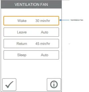
When a programmable schedule is used, there is a ventilation setting for each time period.
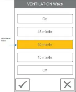
The ventilation fan runs for the set amount of time per hour.
Troubleshooting
When an error occurs an email notification will be sent to the registered Invita Connect mobile or web app account owner
| Description |
| COMMUNICATION ERROR
Communication between the display module and the HVAC Interface Module has been interrupted. This error clears automatically once communication is re-established. |
| MEMORY ERROR
The thermostat memory settings are corrupted. To clear, load the factory defaults in the Toolbox menu. The thermostat will not operate any heating or cooling equipment while this error message is present. |
| INTERNAL ROOM SENSOR FAULT
Due to an open or short circuit, the thermostat is unable to read the internal room temperature sensor. If sensor 1, 2 or 3 is set to room the thermostat continues to operate, otherwise operation stops. The error cannot be field repaired. Contact your tekmar sales representative for warranty or repair procedures. |
| INTERNAL HUMIDITY SENSOR FAULT
Due to an open or short circuit, the thermostat is unable to read the internal humidity sensor. The thermostat stops controlling the humidifier or dehumidifier unless an external humidity sensor is installed on Sensor 3. The error cannot be field repaired. Contact your tekmar sales representative for warranty or repair procedures. |
| SENSOR 1 FAULT
Due to an open or short circuit, the thermostat is unable to read the sensor wired to S1 and Com. The thermostat stops normal operation if sensor 1 is the only active room or floor sensor or if a floor maximum temperature has been set. Check the auxiliary sensor wire for short circuits according to the sensor installation manual. It may be necessary to replace the auxiliary sensor. Once the error has been corrected, the error message automatically clears. |
| SENSOR 2 FAULT
Due to an open or short circuit, the thermostat is unable to read the sensor wired to S2 and Com. The thermostat stops normal operation if sensor 2 is the only active room or floor sensor or if a floor maximum temperature has been set. Check the auxiliary sensor wire for short circuits according to the sensor installation manual. It may be necessary to replace the auxiliary sensor. Once the error has been corrected, the error message automatically clears. |
| SENSOR 3 FAULT
Due to an open or short circuit, the thermostat is unable to read the sensor wired to S3 and Com. The thermostat stops normal operation if sensor 3 is the only active room sensor or if a floor maximum temperature has been set. Check the auxiliary sensor wire for short circuits according to the sensor installation manual. It may be necessary to replace the auxiliary sensor. Once the error has been corrected, the error message automatically clears. |
| Description |
| INTERNET UNAVAILABLE
The thermostat has a WiFi connection to the router but is unable to communicate to the internet. Steps to clear the error include: 1) power off and on the router, 2) power off and on the thermostat. |
| WATER LEAK DETECTOR WARNING
A water leak has been detected and the water line has been shut off. The warning will automatically clear once the water leak detector has been reset. |
| ROOM HOT WARNING
The room temperature is above the Room Hot Warning setting in the Alerts menu. The warning will automatically clear once the room temperature falls below the setting. |
| ROOM COLD WARNING
The room temperature is below the Room Cold Warning setting in the Alerts menu. The warning will automatically clear once the room temperature rises above the setting. |
| LOW HUMIDITY WARNING
The relative humidity is below the Low Humidity Warning setting in the Alerts menu. The warning will automatically clear once the relative humidity rises above the setting. |
| HIGH HUMIDITY WARNING
The relative humidity is above the High Humidity Warning setting in the Alerts menu. The warning will automatically clear once the relative humidity falls below the setting. |
| AUXILIARY HEAT RUN TIME WARNING
The auxiliary heat has been operating continuously longer than the Aux Heat Run Time Warning setting in the Alerts menu. The error clears when the auxiliary heat turns off. There may be problem with your heat pump. Contact your heating professional for service. |
| CHANGE AIR FILTER WARNING
The fan run time has exceeded the Change Air Filter setting in the Alerts menu and requires replacement. To clear the warning, press the Air Filter Replaced button. |
| CHANGE UV LAMP WARNING
The UV lamp run time has exceeded the UV Lamp setting in the Alerts menu and requires replacement. To clear the warning, press the UV Lamp Replaced button. |
| ZIP/POSTAL CODE ERROR
The thermostat was unable to locate the ZIP or Postal Code entered in the WiFi menu. Please try again with a ZIP or Postal Code of a nearby area. |
Warranty
Limited Warranty The liability of tekmar under this warranty is limited. The Purchaser, by taking receipt of any tekmar product (“Product”), acknowledges the terms of the Limited Warranty in effect at the time of such Product sale and acknowledges that it has read and understands same.
The tekmar Limited Warranty to the Purchaser on the Products sold hereunder is a manufacturer’s pass-through warranty which the Purchaser is authorized to pass through to its customers. Under the Limited Warranty, each tekmar Product is warranted against defects in workmanship and materials if the Product is installed and used in compliance with tekmar’s instructions, ordinary wear and tear excepted. The pass-through warranty period is for a period of twenty-four (24) months from the production date if the Product is not installed during that period, or twelve (12) months from the documented date of installation if installed within twenty-four (24) months from the production date.
The liability of tekmar under the Limited Warranty shall be limited to, at tekmar’s sole discretion: the cost of parts and labor provided by tekmar to repair defects in materials and / or workmanship of the defective product; or to the exchange of the defective product for a warranty replacement product; or to the granting of credit limited to the original cost of the defective product, and such repair, exchange or credit shall be the sole remedy available from tekmar, and, without limiting the foregoing in any way, tekmar is not responsible, in contract, tort or strict product liability, for any other losses, costs, expenses, inconveniences, or damages, whether direct, indirect, special, secondary, incidental or consequential, arising from ownership or use of the product, or from defects in workmanship or materials, including any liability for fundamental breach of contract.
The pass-through Limited Warranty applies only to those defective Products returned to tekmar during the warranty period. This LimitedWarranty does not cover the cost of the parts or labor to remove or transport the defective Product, or to reinstall the repaired or replacement Product, all such costs and expenses being subject to Purchaser’s agreement and warranty with its customers.
Any representations or warranties about the Products made by Purchaser to its customers which are different from or in excess of the tekmar Limited Warranty are the Purchaser’s sole responsibility andobligation. Purchaser shall indemnify and hold tekmar harmless from and against any and all claims, liabilities and damages of any kind or nature which arise out of or are related to any such representations or warranties by Purchaser to its customers.
The pass-through Limited Warranty does not apply if the returned Product has been damaged by negligence by persons other than tekmar, accident, fire, Act of God, abuse or misuse; or has been damaged by modifications, alterations or attachments made subsequent to purchase which have not been authorized by tekmar; or if the Product was not installed in compliance with tekmar’s instructions and / or the local codes and ordinances; or if due to defective installation of the Product; or if the Product was not used in compliance with tekmar’s instructions.
THIS WARRANTY IS IN LIEU OF ALL OTHER WARRANTIES, EXPRESS OR IMPLIED, WHICH THE GOVERNING LAW ALLOWS PARTIES TO CONTRACTUALLY EXCLUDE, INCLUDING, WITHOUT LIMITATION, IMPLIED WARRANTIES OF MERCHANTABILITY AND FITNESS FOR A PARTICULAR PURPOSE, DURABILITY OR DESCRIPTION OF THE PRODUCT, ITS NON-INFRINGEMENT OF ANY RELEVANT PATENTS OR TRADEMARKS, AND ITS COMPLIANCE WITH OR NON-VIOLATION OF ANY APPLICABLE ENVIRONMENTAL, HEALTH OR SAFETY LEGISLATION; THE TERM OF ANY OTHER WARRANTY NOT HEREBY CONTRACTUALLY EXCLUDED IS LIMITED SUCH THAT IT SHALL NOT EXTEND BEYOND TWENTY FOUR (24) MONTHS FROM THE PRODUCTION DATE, TO THE EXTENT THAT SUCH LIMITATION IS ALLOWED BY THE GOVERNING LAW.Product Warranty Return Procedure All Products that are believed to have defects in workmanship or materials must be returned, together with a written description of the defect, to the tekmar Representative assigned to the territory in which such Product is located. If tekmar receives an inquiry from someone other than a tekmar Representative, including an inquiry from Purchaser (if not a tekmar Representative) or Purchaser’s customers, regarding a potential warranty claim, tekmar’s sole obligation shall be to provide the address and other contact information regarding the appropriate Representative.
Need help? Go to our website or contact us.tekmarControls.com | [email protected] | 1-800-438 3903

A WATTS Brand
All specifications are subject to change without notice
Tel: 1-800-438-3903 • Fax: (250) 984-0815tekmarControls.com
 report this ad
© 2020 tekmar
References
[xyz-ips snippet=”download-snippet”]