TEKTELIC T0007242/T0007422 Kona Enterprise Gateway User Guide
Product Description
Overview
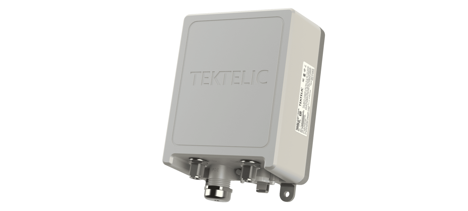
The Kona Enterprise Gateway module, shown in Figure 1, is a low power micro-cell gateway with wide-area coverage (up to 500 km2 ). The module consists of 1 Semtech SX1301 base-band processor multiplexed through an FPGA to provide 8 simultaneous narrowband channels. The design offers both downlink and uplink operations in time-duplex mode. The gateway supports internal LoRa antenna, internal GPS, copper Ethernet backhaul, and optional 3G/4G wireless backhaul with internal Cellular antennas. The gateway also supports external LoRA and Main Cellular antennas via switched-N bulk connector. The Kona Enterprise Gateway is powered through Power Over Ethernet (PoE 802.3af).
Table 1 presents the currently available Kona Enterprise Gateway models.
| Model | Order Code | 3G/4G modem | Region | Frequency Band |
| T0007242 | MOEN1LUS915 | Yes | North America | 915 |
| T0007422 | MOEN1NUS915 | No | North America | 915 |
illustrates the Kona Enterprise Gateway external form-factor. All models share the same mechanical form-factor.
Physical Interfaces
illustrates the bulkhead layout for the Kona Enterprise Gateway.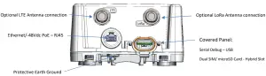
The Kona Enterprise Gateway connectors are listed in Table 2.
Kona Enterprise Gateway Interface Connector Types
| Interface | Connector Type |
Mating Connector |
| LoRa Antenna | N-Type female | Industry standard N-Type male |
| Cellular Antenna | N-Type female | Industry standard N-Type male |
|
Interface |
Connector Type |
Mating Connector |
| Copper Ethernet | RJ45 Modular Jack | RJ45 modular plug followed by CAT 5e cable |
| Earth Ground | Compression lug | Industry standard single-hole lug, M4 (#8) |
Specifications
The Kona Enterprise Gateway specifications are listed in Table 3.
| Attribute | Specification |
| Dimensions | 208x146x80 mm |
| Weight | 1160 g |
| Operating Temperature | -40 °C to 60 °C |
| Relative Humidity | 10% to 100 % Condensing |
| Operating Altitude | -60 m to 4,000 m (-197 ft to 13,123 ft) |
| Power Input | IEEE 802.3af, Mode A or Mode B or 4-pair Mode 48 VDC nominal, 37 to 57 VDC operating range0.3 A maximum |
| Ingress Protection | IP-67 |
| Regulatory Compliance | Safety: UL/CSA/EN/IEC 62368-1Radiated Immunity: EN 61000-4-3 ESD Immunity: EN 61000-4-2EFT Immunity: EN 61000-4-4 Conducted Immunity: EN 61000-4-6 Surge Immunity: EN 61000-4-5Emissions: FCC pt. 15.109 Class B, FCC pt. 15.209, FCC pt. 15.247, EN 300 220, EN 301 489 |
Installation
Overview
- The Kona Enterprise Gateway has no internal field serviceable parts. The Gateway module must only be opened by an approved TEKTELIC service center.
- All installation practices must be in accordance with the local and national electrical codes.
- Do not work on the system during periods of lightning activity.
- The Kona Enterprise Gateway is considered permanently connected equipment. The Protective Earth Ground connection (that is, the chassis ground) is always required.
- Ensure the Kona Enterprise Gateway Protective Earth Ground connection is properly terminated prior to the connection of any other interface.
- The Kona Enterprise Gateway contains primary lightning surge suppression on the copper Ethernet port, and the LoRa RF antenna port. The primary lightning protectors have the ability to bridge the interface to chassis during over-voltages. Ensure that the Protective Earth Ground connection is always in place.
- An external inline surge protector must be applied to the External Cellular antenna port when used.
- Ensure that the Kona Enterprise Gateway is secured to eliminate any physical hazard to people or property. The Gateway must be securely mounted according to the mounting instructions prior to any cable connection and operation.
- The Kona Enterprise Gateway does not contain a power disconnection device; a readily accessible disconnection device must be incorporated external to the Kona Enterprise Gateway.
- The Kona Enterprise Gateway can only be powered either via PoE (Power-Over-Ethernet) or passive POE combiner. Please note that when using a passive POE combiner, it is vital to use a (minimum 10W) 48V power supply with Hiccup Mode Current Limiting.
- Always ensure the Ethernet connection port and 3G/4G Modem SIM card access port are properly sealed after installation or servicing.
- The Kona Enterprise Gateway is intended to be installed in controlled area like tower or roof top building with restricted access to general public. The installation and maintenance must be performed by professional trained RF technician.
Unpacking and Inspection
The following should be considered during the unpacking of a new Kona Enterprise Gateway.
- Inspect the shipping carton and report any significant damage to TEKTELIC.
- Unpacking should be conducted in a clean and dry location when possible.
- Do not discard the shipping box or foam inserts as they will be required if a unit is returned for repair or re-configuration.
Dual SIM Slot Operation
The Kona Enterprise Gateway is equipped with a dual SIM slot which can be configured to the user’s liking. The primary and secondary slots can be configured in the software configuration. Prior to inserting or replacing SIM, please ensure that the unit is turned off. If 2 SIM cars are used, and the primary SIM fails or is missing, the failover mechanism will automatically switch over to the secondary SIM. When only one SIM is used, please place the SIM in slot 0 (primary SIM / inner slot) as indicated by Figure 4. Slot 1 is for the secondary SIM (outer slot).
Required Equipment for Installation
The Kona Enterprise Gateway is intended to be installed in controlled area like tower or roof top building with restricted access to general public. The installation and maintenance must be performed by professional trained RF technician.
The following tools are required to install the Kona Enterprise Gateway module:
- A 6 point metric socket set and torque wrench drive.
- Anti-oxidant compound (NO-OX-ID, Penetrox, Noalox, Ox-Gard or equivalent).
- A small wire brush.
- A clean cloth.
- Weatherproofing tape kit for the RF connector (Scotch Wireless Weatherproofing Kit, WK101 recommended).
- Supplied pole mounting accessories (shown in Figure 6) for pole mounting or appropriate screws or bolts (four sized M6) with any required anchors according to the wall construction for wall mounting.
Kona Enterprise Gateway Mounting
Kona Enterprise Gateway PoE must be mounted to a vertical pole or wall using the supplied mounting hardware which attaches to the back of the module as illustrated in 5. The vertical orientation is required for the GPS to function properly.
When mounted, the Gateway module must be oriented with the connector bulkhead pointed down towards earth as shown in Figure 6.
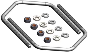
Kona Enterprise Gateway Module Pole Mounting Accessories
Ground Cable Installation
The Kona Enterprise Gateway is considered Permanently Connected Equipment and requires a permanently connected Protective Earth Ground (PEG) conductor. The Protective Earth Ground connection is made through a M4/#8 on center hole lug with 10mm maximum OD to the ground termination point illustrated in Figure 9. The recommended ground cable gauge is #10 AWG. The Kona Enterprise Gateway grounding system shall follow local and national electrical codes. The Protective Earth Ground conductor terminated at the hole lug point is mandatory and must be the first connection made to the Kona Enterprise Gateway during installation. Proper routing and termination of this cable is key to robust lightning withstand performance; in high susceptibility installations, every effort shall be made to minimize connection inductance and ground bed resistance. The ground cable installation steps are as follows:
- Lightly abrade the surface of the casting ground area with a fine wire brush to remove the oxide layer.
- Use a clean cloth to remove any debris from this surface.
- Immediately coat the contact surface with a thin layer of anti-oxidant compound.
- Install the ground cable through its single hole lug onto the chassis ground point using the supplied M4x0.7 – 12mm bolt with flat, lock, and star washers, torqued to 2.4Nm (22 in·lbs).

RF Cable Installation
The Kona Enterprise Gateway installation allows connection to an external LoRa RF antenna and an external Cellular RF antenna. The RF cables attach to an N-Type connector located on the bulkhead of the Gateway. Torque the cable RF connector to 0.79 to 1.13 Nm (7 to 10 in·lbs). The N-Type connector interface to a cable is not water proof and must be taped. TEKTELIC recommends taping with Scotch Wireless Weatherproofing Kit, WK 101. Follow the taping procedures outlined by the supplier of this tape system.Note that the Cellular antenna port in not surge protected internal to the Gateway, an external surge suppressor such as Polyphaser p/n TSX-NFM or equivalent is recommended any time an external cellular antenna is connected.
Copper Ethernet Cable Installation
The Kona Enterprise Gateway Ethernet port must be used to power the gateway and may further be used for backhaul or commissioning and maintenance. As shown in Figure 10, pass the Ethernet cable through the cable gland supplied with the module. Plug the cable into the modular jack on the module, then tighten the cable gland to the module with torque 6Nm.The Ethernet cable must have minimum 24 AWG conductors and shall be rated according to local and national electrical codes.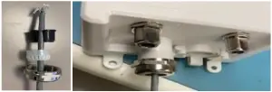
Radio Compliance Statements
Federal Communications CommissionThis device complies with Part 15 of the FCC Rules. Operation is subject to the following two conditions:
- This device may not cause harmful interference, and
- This device must accept any interference received, including interference that may cause undesired operation.
Changes or modifications not expressly approved by the party responsible for compliance could void the user’s authority to operate the equipment.
This equipment has been tested and found to comply with the limits for a Class A digital device, pursuant to Part 15 of the FCC Rules. These limits are designed to provide reasonable protection against harmful interference in a residential installation. This equipment generates uses and can radiate radio frequency energy and, if not installed and used in accordance with the instructions, may cause harmful interference to radio communications. However, there is no guarantee that interference will not occur in a particular installation. If this equipment does cause harmful interference to radio or television reception, which can be determined by turning the equipment off and on, the user is encouraged to try to correct the interference by one of the following measures:
- Reorient or relocate the receiving antenna.
- Increase the separation between the equipment and receiver.
- Connect the equipment into an outlet on a circuit different from that to which the receiver is connected.
- Consult the dealer or an experienced radio/TV technician for help.
To comply with FCC/IC RF exposure limits for general population / uncontrolled exposure, the antennas used for this transmitter must be installed to provide a separation distance of at least 40 cm from all persons and must not be co-located or operating in conjunction with any other antenna or transmitter. This product must be installed by professional trained RF technicians.
Industry Canada
This Device complies with Industry Canada License-exempt RSS standard(s). Operation is subject to the following two conditions:
- This device may not cause interference, and
- This device must accept any interference, including interference that may cause undesired operation of the device.
This radio transmitter 22504-T0007323 has been approved by Industry Canada to operate with the antenna types listed below with the maximum permissible gain indicated. Antenna types not included in this list, having a gain greater than the maximum gain indicated for that type, are strictly prohibited for use with this device. The required antenna impedance is 50 ohms.
Only omnidirectional type antennas with maximum gain of 8dBi can be used for the LoRa radios of this product. Maximum output power at antenna port allowed is 27.5dBm.
Antenna(s) shall be installed to location providing a separation distance of at least .40 m from any human body.
During product operation, always keep a separation distance of at least 0.40m from any connected antenna(s). Before servicing the product, the antenna(s) or cables, turn off the transmission function or the unit power if you have to get closer than the minimum separation distance. This product must be installed by professional trained RF technicians.
report this ad
[xyz-ips snippet=”download-snippet”]