Tektronix® 4 Series Mixed Signal Oscilloscopes Declassification and Security Instructions
MSO44, MSO46
Warning: The servicing instructions are for use by qualified personnel only. To avoid personal injury, do not perform any servicing unless you are qualified to do so. Refer to all safety summaries prior to performing service.
Register now!Click the following link to protect your product.www.tek.com/register

Copyright © Tektronix. All rights reserved. Licensed software products are owned by Tektronix or its subsidiaries or suppliers, and are protected by national copyright laws and international treaty provisions. Tektronix products are covered by U.S. and foreign patents, issued and pending. Information in this publication supersedes that in all previously published material. Specifications and price change privileges reserved.
TEKTRONIX and TEK are registered trademarks of Tektronix, Inc.
Contacting Tektronix
Tektronix, Inc.14150 SW Karl Braun DriveP.O. Box 500Beaverton, OR 97077USA
For product information, sales, service, and technical support:
- In North America, call 1-800-833-9200.
- Worldwide, visit www.tek.com to find contacts in your area.
Preface
This document helps customers with data security concerns to clear or sanitize 4 Series MSO instruments without factory-installed Option 4-SEC.
This series of instruments contain a processor system with non-removable mass storage.
These products have data storage (memory) devices and data export interfaces (USB and Ethernet). These instructions describe how to clear or sanitize the memory devices and disable the data output interfaces. The instructions also describe how to sanitize an instrument that is not functioning.
Reference
The procedures in this document are written to meet the requirements specified in:
- National Industrial Security Program Operating Manual (NISPOM), DoD 5220.22–M, Chapter 8
- Defense Security Service Manual for the Certification and Accreditation of Classified Systems under the NISPOM
Supported products
Tektronix 4 Series Mixed Signal Oscilloscope products are covered by this document.
Terms
The following terms may be used in this document:
- Clear. This eradicates data on media/memory before reusing it in a secured area. All reusable memory is cleared to deny access to previously stored information by standard means of access.
- Erase. This is equivalent to clear.
- Media. Storage/data export device. A device that stores or exports data from the instrument, such as a USB flash drive or USB port.
- Sanitize. This removes the data from media/memory so that the data cannot be recovered using any known technology. This is typically used when the device is moved (temporarily or permanently) from a secured area to a nonsecured area.
- Scrub. This is equivalent to sanitize.
- Remove. This is a physical means to clear the data by removing the memory device from the instrument. Instructions are available in the product service manual.
- User-Accessible. The user can directly retrieve the memory device contents.
- User-Modifiable. The memory device can be written to by the user during normal instrument operation, using the instrument user interface or remote control.
- Volatile memory. Memory that loses data when the instrument is powered off.
- Nonvolatile memory. Memory that retains data when the instrument is powered off.
- Power off. Some instruments have a “Standby” mode, in which power is still supplied to the instrument. For clearing data, putting the instrument in Standby mode does not qualify as powering off. For these products, you must either push a rear-panel OFF switch or remove the power source from the instrument.
- Instrument Declassification. A term that refers to procedures that must be undertaken before an instrument can be removed from a secure environment. Declassification procedures include memory sanitization, memory removal, and sometimes both.
Clear and sanitize procedures
Non-volatile and volatile memory device table terminology
The tables in this section use the following terms:
- User data. Describes the type of information stored in the device. Refers to waveforms or other measurement information representing signals connected to the instrument by users.
- User settings. Describes the type of information stored in the device. Refers to instrument settings that can be changed by the user.
- Both. Describes the type of information stored in the device. It means that both user data and user settings are stored in the device.
- None. Describes the type of information stored in the device. It means that neither user data or user settings are stored in the device.
- Directly. Describes how data is modified. It means that the user can modify the data.
- Indirectly. Describes how data is modified. It means that the instrument system resources modifies the data and that the user cannot modify the data.
Memory devices
The following tables list the volatile and non-volatile memory devices in the instrument.
Volatile memory devices
These are the memory capacities at the time of publishing this document, but are subject to change.
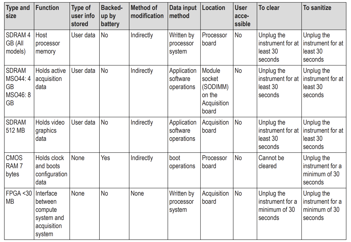
Non-volatile memory devices
These are the memory capacities at the time of publishing this document, but are subject to change.

Media and data export devices
The following table lists the data export devices in the instrument.

How to sanitize a working instrument
Sanitize means that all data in non-volatile memory is changed or overwritten such that the original data is no longer in memory, and that the data cannot be recovered using any known technology. You typically do a sanitize operation when you:
- Turn the instrument over to another person or department
- Move an instrument (temporarily or permanently) from a secured area to a nonsecured area
- Send an instrument to Tektronix for calibration and/or repair
Sanitizing is done through commands on the instrument. To sanitize the instrument:
- Remove any USB memory devices from the instrument, and store or destroy the USB memory devices in accordance with your organization’s guidelines.
- Clear the Network Configuration password (if set):a. Enter the instrument’s IP address into a Web browser on a PC that has network access to the instrument.b. Click the Security for Network Config link on the left side of the screen.c. Click Submit:
- If a password was set for this function, you are requested to enter the password. If the password is accepted, the password is set to blank (the default setting of the access password fields).
- If a password was not set for this function, the screen displays the message that the password was successfully changed (to a blank password).
- Clear the network mDNS Hostname and description:a. Enter the instrument’s IP address into a Web browser on a PC that has network access to the instrument.b. Click the Network Configuration link on the left side of the screen.c. Delete any existing text in both of the Host Settings fields.d. Click the Host Settings Submit button. A message appears stating that the field is empty, and will be configured to the original factory default value.e. Click OK. The message closes and the fields are restored to their original factory settings.
- Clear the Ethernet port settings:a. Disconnect the Ethernet cable from the instrument.b. Open the Utility > I/O menu.c. Clear all information from the Host Name, Domain Name, and Service Name fields.d. Click the Network Address Manual button.e. Manually change the Instrument IP Address, Subnet Mask, Gateway IP Address, and DNS IP Address information to 00.00.00.00.f. Tap Apply Changes. It will take several moments for the changes to take effect. g. Tap outside the menu to close the menu.
 Note: You can also clear the instrument Address settings by accessing the instrument’s web-based interface. Connect the instrument to your network, enter the instrument’s IP address into a Web browser on a PC that is connected to the same network as the instrument, click the Network Configuration link on the left side of the screen, select the Manual TCP/IP Mode box, clear all information from all fields, and click the Submit button for the Address Settings.
 - Open the Utility > Security menu and clear the password used to access enabling/disabling ports and software updates. See the Help system for information on the Security menu functions.
- Tap TekSecure Erase Memory to clear/reset internal memory.
- Push the Default Setup button before powering off the instrument.
 Note: You can also clear the instrument Address settings by accessing the instrument’s web-based interface. Connect the instrument to your network, enter the instrument’s IP address into a Web browser on a PC that is connected to the same network as the instrument, click the Network Configuration link on the left side of the screen, select the Manual TCP/IP Mode box, clear all information from all fields, and click the Submit button for the Address Settings.
How to sanitize a non-functional instrument
Do the following to sanitize your instrument if it is not functioning and must be returned to Tektronix for repair:
- Remove all external USB memory devices and store or destroy the USB memory devices in accordance with your organization’s guidelines.
- Follow the instructions in Processor board removal instructions on page 9 to get access to and remove the Processor board, which contains user data and settings. Store or destroy the Processor board in accordance with your organization’s guidelines.
- Reassemble the instrument without the Processor board and return it to Tektronix. The instrument will then be repaired and calibrated as necessary.
In North America, contact the Tektronix Customer Care Center (1-800-833-9200) for assistance with returning the instrument to a repair center. Worldwide, visit www.tektronix.com to find contacts in your area.
Processor board removal instructions
Use these procedures to remove the Processor board when you need to sanitize a nonfunctional instrument before returning the instrument to Tektronix for repair. Refer to your company’s internal policies regarding handling or disposal of the Processor board. A new Processor board is installed and the instrument is repaired and adjusted as necessary.
![]() Warning: Before doing this procedure, disconnect the power cord from the line voltage source. Failure to do so could cause serious injury or death.
Warning: Before doing this procedure, disconnect the power cord from the line voltage source. Failure to do so could cause serious injury or death.
![]() CAUTION: To avoid damaging other circuits in the instrument, perform the following procedure in a static-safe environment with proper electrostatic discharge controls in place.
CAUTION: To avoid damaging other circuits in the instrument, perform the following procedure in a static-safe environment with proper electrostatic discharge controls in place.
![]() CAUTION: Do not lay the instrument on its front while disassembling the instrument. All disassembly steps can be done with the instrument positioned as instructed in the steps. Laying the instrument on its front can damage the controls.
CAUTION: Do not lay the instrument on its front while disassembling the instrument. All disassembly steps can be done with the instrument positioned as instructed in the steps. Laying the instrument on its front can damage the controls.
Access the chassis
- Position the instrument in the normal operating position.
- Remove the handle from the instrument:a. Use a Torx T-10 screwdriver to remove two screws from each end of the handle.b. Remove the handle, external handle hubs, and screws aside.
- Remove the metal grill from the rear of the instrument:a. Use a Torx T-10 screwdriver to remove the ten (10) screws located on the grill.b. Remove the grill.
- Remove the internal handle hubs:a. Use a Torx T-10 screwdriver to remove the eight (8) Torx T-10 screws from the internal hub assemblies (four screws on each hub).b. Remove the internal handle hub assemblies and set aside. Keep the hub assemblies together for each side.
- Remove the feet from the bottom of the instrument:a. Position the instrument so the bottom is facing up.b. Open the feet.c. Use a Torx T-10 screwdriver to remove the four (4) Torx T-10 screwdriver to screws from each foot.d. Remove the feet and set aside.
- Remove the rear plastic case from the instrument:a. Use a Torx T-10 screwdriver to remove the six (6) screws from the back of the instrument case.b. Lift the rear plastic case off the back of the instrument, and set it aside.
- Separate the rear metal chassis from the front chassis (with the instrument still in the bottom-up position):a. Use a Torx T-10 screwdriver to remove the 25 screws securing the rear chassis to the front chassis. There are 24 screws around the chassis edges, and one (1) screw beneath the HDMI connector.b. Remove the three (3) nuts and washers from the BNC connectors.c. Gently pry apart the rear chassis assembly. The rear chassis is held in position mostly by the friction of the three BNC connectors.d. Continue prying the chassis apart until you have the two halves separated and can access the cables.e. Disconnect the two power cable connectors.f. Disconnect the smaller cables on the other end of the chassis.g. Set the rear chassis aside.
 d. Remove the feet and set aside.
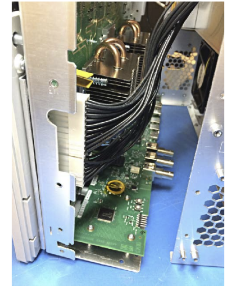 e. Disconnect the two power cable connectors.
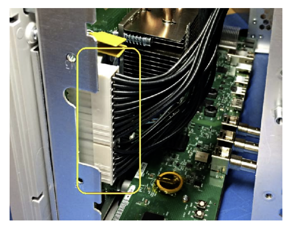 f. Disconnect the smaller cables on the other end of the chassis.
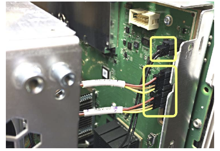 g. Set the rear chassis aside.
Remove the Processor board
- Use a Torx T-10 screwdriver to remove the seven (7) screws from the Processor board.
- Lift and pull the Processor board away from the chassis. It is still connected with cables, so be careful to not pull it too far.
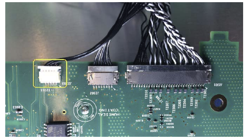
- Carefully rotate the Processor board 180° counterclockwise to get access to the cable connectors.
- Disconnect the small white plastic cable connector.
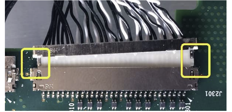
- Position your fingernails so that they are between the edge of the larger-size cable connector and its board connector.
- Gently push and rock the cable connector side to side to move the wire connector out of the board connector.
- Repeat these steps to disconnect the remaining smaller cable connector.
- Remove the Processor board. Secure or dispose of the Processor board as directed by your organization’s internal policies regarding handling or disposal of secure devices.
- Reassemble the instrument by using the disassembly steps in reverse order. Tighten the Torx T-10 screws to 0.65 Newton meters.
- Package the reassembled instrument, minus the Processor board, and ship to your nearest Tektronix Service Center for repairs. A new Processor board will be installed


Repair charges
Replacement of damaged and missing hardware is charged according to the rate at the time of replacement.
References
[xyz-ips snippet=”download-snippet”]