Tektronix TIVP IsoVu Measurement System
![]()
Operating information
The Tektronix TIVP IsoVu™ Measurement System offers a completely galvanically isolated (optical isolation) system. Isolation is used to greatly increase the accuracy of differential measurements with rapidly slewing reference voltages and to isolate hazardous voltages from the oscilloscope.The TIVP is designed for use with Tektronix 4/5/6 Series MSO Oscilloscopes running software version 1.28 or higher.Refer to the TIVP User Manual (071-3692-xx) for complete operating information and product specifications. The manual is available for download at www.tek.com/downloads.The following illustration shows how to connect the probe to your instrument and the controls on the compensation box.
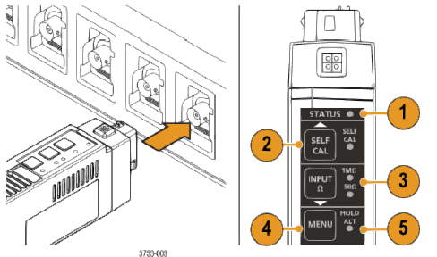
Controls and indicators
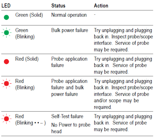
STATUS indicator.
SELF CAL button and LED indicator. Press to start self-calibration routine.

INPUT Termination button and LED indicator. With no tip attached, press to toggle the sensor head between 50 Ω and 1 MΩ termination.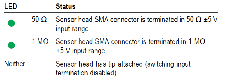
ALT Mode indicator.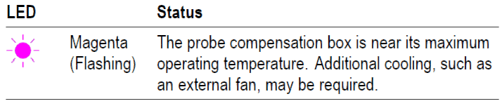
Compensating the probe
The TIVP contains a self-calibration routine that corrects Gain Accuracy, DC offset, and frequency response. These parameters change as the probe warms up to its operating temperature and remain constant once the temperature reaches steady-state. An indicator LED on the probe compensation box and the SELFCAL:STATE? PI command both indicate whether a self-calibration is RECOMMENDED, RUNNING, or PASSED.Before making critical measurements, run SELF CAL to ensure the TIVP is compensated. The sensor tip does not need to be removed from the test point to successfully complete a self-calibration.
- Connect TIVP to an oscilloscope channel.
- Press the SELF CAL button on the probe compensation box. Alternatively, send the CH<x>:PROBE:SELFCAL EXECUTE PI command to start the self-calibration programmatically.
- The SELF CAL LED will blink while the self-calibration is in process.
- The SELF CAL LED is amber when there is a change and a self-calibration is recommended. The LED is green if the last self-calibration is still valid.
Cable handling
Tektronix TIVP probes operate using several optical fibers within a single cable between the compensation box and probe head. Therefore, standard optical fiber handling practices are required. Avoid tight radius bends, crushing, crimping, twisting, or otherwise stressing the fiber.Standard accessories
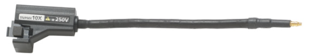
MMCX probe tip
The 10X MMCX tip is included in every TIVP probe. The MMCX tip is recommended for the best bandwidth and CMRR performance. 0.100″ Square Pin and 0.200″ Wide Square Pin tips are available as optional accessories. Reorder part number: TIVPMX10X
Probe bipodUsed to hold probe. TIVP can rotate in holder to accommodate square pin headers. Reorder part number:352-1179-xx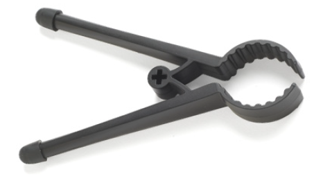
Probe tip adapterAdaptanMMCXIsoVutipto standard 0.100″ spaced, 0.025″ square pins. Reorder part number:131-9717-xx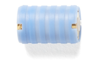
SMA wrench/driver tool5/16″ wrench for use on SMA connector. Reorder part number:003-1947-xx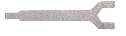
IsoVu carrying caseSoft case (with foam insert) protects the TIVP and enforces the optical fiber minimum bend radius. Reorder part number:016-2147-xx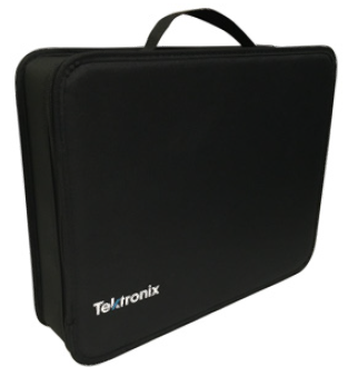
Optional accessories
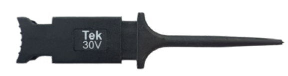
50XMMCXsensortipTIVPMX50X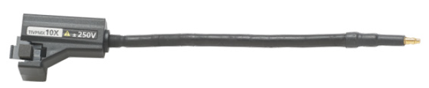
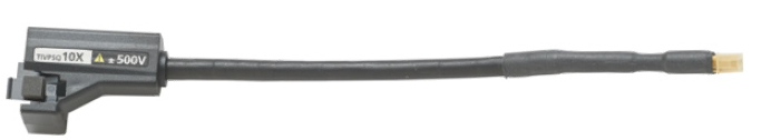
100X sensor tip cable with 0.100″ spaced square pin connectorsTIVPSQ100X
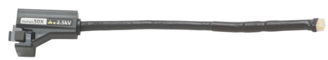
500X sensor tip cable with 0.200″ spaced wide square pin connectorTIVPWS500X
1X MMCX sensor tipTIVPMX1X
Square Pin to MMCX Adapter, 0.062″ Spacing131-9677-xx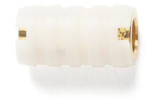
Probe Tip Tripod Support352-1170-xx

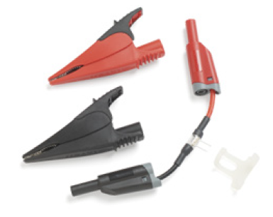
Lead, MMCX to IC Grabber196-3546-xx
Lead, Square Pin to IC Grabber196-3547-xx
Lead, Wide Square Pin to Banana Jack020-3189-xx
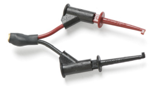
MMCX Y-LeadTPR4KIT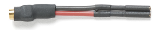
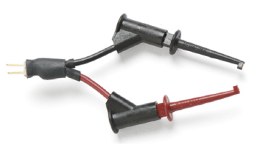
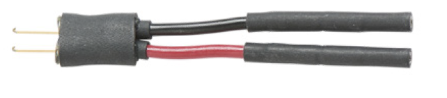
Square Pin Y-lead196-3434-xx
MicroCKT grabbers206-0569–xx
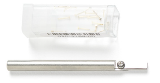
Spare Pins for 0.062″ Spaced Test Points020-3169-xxSolder Aid for 0.062″ Spaced Square Pins003-1946-xx
Clearance requirements
The unique common mode voltage range of the measurement system allows it to be used in the presence of high frequency/high voltage common mode signals. It is important to observe all precautions while using this product.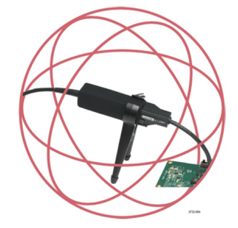
WARNING. Electrical shock can occur while using this measurement system. The system is intended to isolate the operator from hazardous input voltages (common voltages); the plastic case of the sensor head and the shield on the sensor tip cable do not supply safe isolation. Maintain the safe clearance from the sensor head and sensor tip cable while the measurement system is connected to the energized circuit as recommended in this document. Do not access the RF Burn Hazard Zone while taking measurements on a live circuit. RF burn hazard zone is 1 meter (40 in) on all sides
Specifications
Physical specifications
Net weight: Tip cable assembly: 25g (0.055 lb)(Weight does not include accessories and packaging.): Probehead: 0.363kg(0.8lbs) Compensation box: 0.816kg (1.8lbs)Sensor tip cable length: 20.03 cm (7.886 inches)Fiber cable length: 2 meter (6.56 ft)
Compliance information
This section lists the Safety and Environmental standards with which the instrument complies. This product is intended for use by professionals and trained personnel only; it is not designed for use in households or by children.Safety complianceThis section lists the safety standards with which the product complies and other safety compliance information.EU low voltage directiveCompliance was demonstrated to the following specification as listed in the Official Journal of the European Union:Low Voltage Directive 2014/35/EU.
- EN 61010-1. Safety Requirements for Electrical Equipment for Measurement, Control, and Laboratory Use – Part 1: General Requirements.
U.S. nationally recognized testing laboratory listing
- UL 61010-1. Safety Requirements for Electrical Equipment for Measurement, Control, and Laboratory Use – Part 1: General Requirements.
Canadian certification
- CAN/CSA-C22.2 No. 61010-1. Safety Requirements for Electrical Equipment for Measurement, Control, and Laboratory Use – Part 1: General Requirements.
Additional compliances
- IEC 61010-1. Safety Requirements for Electrical Equipment for Measurement, Control, and Laboratory Use – Part 1: General Requirements.
- EN 60825-1/IEC 60825-1. Safety of Laser Products-Part 1: Equipment Classification and Requirements – Edition 3 (2014)
- US 21CFR PT1010 Performance Standard for Electronic Parts 2015.
- US 21CFR PT1040 Performance Standards for Light Emitting Products 2015.
Equipment typeTest and measuring equipment. CLASS 1 LASER PRODUCT.
Pollution degree descriptions
A measure of the contaminants that could occur in the environment around and within a product. Typically the internal environment inside a product is considered to be the same as the external. Products should be used only in the environment for which they are rated.
- Pollution degree 1. No pollution or only dry, nonconductive pollution occurs. Products in this category are generally encapsulated, hermetically sealed, or located in clean rooms.
- Pollution degree 2. Normally only dry, nonconductive pollution occurs. Occasionally a temporary conductivity that is caused by condensation must be expected. This location is a typical office/home environment. Temporary condensation occurs only when the product is out of service.
- Pollution degree 3. Conductive pollution, or dry, nonconductive pollution that becomes conductive due to condensation. These are sheltered locations where neither temperature nor humidity is controlled. The area is protected from direct sunshine, rain, or direct wind.
- Pollution degree 4. Pollution that generates persistent conductivity through conductive dust, rain, or snow. Typical outdoor locations.
Pollution degree ratingPollution degree 2 (as defined in IEC 61010-1). Rated for indoor, dry location use only.IP ratingIP20 (as defined in IEC 60529).Measurement and overvoltage category descriptionsMeasurement terminals on this product may be rated for measuring mains voltages from one or more of the following categories (see specific ratings marked on the product and in the manual).
- Category I. Circuits not directly connected to a mains supply.
- Category II. Circuits directly connected to the building wiring at utilization points (socket outlets and similar points).
- Category III. In the building wiring and distribution system.
- Category IV. At the source of the electrical supply to the building.
NOTE. Only measurement circuits have a measurement category rating. Other circuits within the product do not have either rating.
Environmental considerations
This section provides information about the environmental impact of the product.Product end-of-life handlingObserve the following guidelines when recycling an instrument or component:Equipment recycling. Production of this equipment required the extraction and use of natural resources. The equipment may contain substances that could be harmful to the environment or human health if improperly handled at the product’s end of life. To avoid release of such substances into the environment and to reduce the use of natural resources, we encourage you to recycle this product in an appropriate system that will ensure that most of the materials are reused or recycled appropriately.
This symbol indicates that this product complies with the applicable European Union requirements according to Directives 2012/19/EU and 2006/66/EC on waste electrical and electronic equipment (WEEE) and batteries. For information about recycling options, check the Tektronix Web site (www.tek.com/productrecycling).
Important safety information
This manual contains information and warnings that must be followed by the user for safe operation and to keep the product in a safe condition.Any servicing is not allowed, please contact Tektronix service.Laser source is contained in the products.General safety summaryUse the product only as specified. Review the following safety precautions to avoid injury and prevent damage to this product or any products connected to it. Carefully read all instructions. Retain these instructions for future reference.The product is designed to be used by trained personnel only.Before use, always check the product with a known source to be sure it is operating correctly.To Avoid Fire or Personal InjuryConnect and disconnect properly. Do not connect or disconnect sensor tip cables, test leads, or accessories while they are connected to a voltage source. Use only test leads and accessories supplied with the product, or indicated by Tektronix to be suitable for the product.
Observe all terminal ratings. To avoid fire or shock hazard, observe all ratings and markings on the product. Consult the product manual for further ratings information before making connections to the product. Do not exceed the Measurement Category (CAT) rating and voltage or current rating of the lowest rated individual component of a product or accessory.Do not apply a potential that exceeds the maximum rating.Do not operate without covers.Avoid Exposed Circuitry. Do not touch exposed connections and components when power is present.Do not operate with suspected failures.. If you suspect that there is damage to this product, have it inspected by qualified service personnel.Disable the product if it is damaged.Do Not Operate in Wet/Damp Conditions.Do Not Operate in an Explosive Atmosphere.Keep Product Surfaces Clean and Dry.Clean with Dry Cloth Only.
Sensor tip cables
Maintain safe clearance from the sensor head and sensor tip cable while connected to the energized circuit as recommended in this manual.Remove the sensor tip cable and adapters from the test circuit when not in use.Leave the sensor tip cable connected to the sensor head when not in use.Use only correct Measurement Category (CAT), voltage, temperature, altitude, and amperage rated sensor tip cables and accessories for any measurement.
Beware of high voltages. Understand the voltage ratings for the product you are using and do not exceed those ratings. It is important to know and understand the maximum measurement voltage rating of the product. The voltage rating depends on the measurement category, the instrument, and your application. Refer to the Specifications section of the manual for more information.
WARNING. To prevent electrical shock, do not exceed the maximum measurement or maximum voltage category.
Connect and disconnect properly.
CAUTION. To avoid damage to the equipment, de-energize the test circuit before connecting or disconnecting the sensor tip cable.
Terms in This Manual.These terms may appear in this manual:
WARNING. Warning statements identify conditions or practices that could result in injury or loss of life.CAUTION. Caution statements identify conditions or practices that could result in damage to this product or other property.Isolated, electrically floating. The terms isolated, electrically floating, and galvanically isolated are used in this document to indicate a measurement where there is no direct conduction path to earth ground.
Symbols and terms on the product
These terms may appear on the product:
- DANGER indicates an injury hazard immediately accessible as you read the marking.
- WARNING indicates an injury hazard not immediately accessible as you read the marking.
- CAUTION indicates a hazard to property including the product.
When this symbol is marked on the product, be sure to consult the manual to find out the nature of the potential hazards and any actions which have to be taken to avoid them. (This symbol may also be used to refer the user to ratings in the manual.)
Warranty informationFor warranty information, go to www.tek.com/warranty
![]()
References
[xyz-ips snippet=”download-snippet”]