![]()
INSTRUCTION MANUAL

OPM210 • OPM220Fiber Optic Power Meter
 Read and understand all of the instructions and safety information in this manual before operating or servicing this tool.
Register this product at www.TempoCom.com
55500197 REV11 © 2020 Tempo Communications Inc. 09/20
KEEP THIS MANUAL
Description
-
-
- The OPM210 power meter measures optical power at 850 nm, 1300 nm, 1310 nm, 1490nm, 1550nm and 1625 nm between a power range of +6 to -70dBm. The OPM210 is supplied standard with a universal 2.5mm bulkhead. The OPM210 is supplied with a 1mW Visual Fault Locator that is used to measure fiber breaks, discontinuities and Macrobends. The VFL has a universal 2.5mm interface with an optional 1.25mm adapter available.
- The OPM220 power meter measures optical power at 850 nm, 1300 nm, 1310 nm, 1490nm, 1550nm and 1625 nm between a power range of +26 to -40dBm. The OPM210 is supplied standard with a universal 2.5mm bulkhead. The OPM220 is supplied with a 1mW Visual Fault Locator that is used to measure fiber breaks, discontinuities and Macrobends. The VFL has a universal 2.5mm interface with an optional 1.25mm adapter available.
-
Safety
Safety is essential in the use and maintenance of Tempo Communications tools and equipment. This instruction manual and any markings on the tool provide information for avoiding hazards and unsafe practices related to the use of this tool. Observe all of the safety information provided.
Purpose of This Manual
This instruction manual is intended to familiarize all personnel with the safe operation and maintenance procedures for the Tempo Communications OPM210 and OPM220 instruments. Keep this manual available to all personnel. Replacement manuals are available upon request at www.TempoCom.com.
Important Safety Information
 SAFETY ALERT SYMBOL
This symbol is used to call your attention to hazards or unsafe practices that could result in an injury or property damage. The signal word, defined below, indicates the severity of the hazard. The message after the signal word provides information for preventing or avoiding the hazard.
DANGER
Immediate hazards which, if not avoided, WILL result in severe injury or death.
WARNING
Hazards which, if not avoided, COULD result in severe injury or death.
CAUTION
Hazards or unsafe practices which, if not avoided, MAY result in injury or property damage.
WARNING
 Read and understand this material before operating or servicing this equipment. Failure to understand how to safely operate this tool could result in an accident causing serious injury or death.
WARNING
 Electric shock hazard:Contact with live circuits could result in severe injury or death.
Important Safety Information

The OPM210 and OPM220 instrument has a laser device, a Visual Fault Locator (VFL) conforming to the requirements of CDRH, CFR 1040, Subchapter J. While there is no potential for eye damage due to unaided direct exposure, users should always avoid looking directly into the output port. The use of optical viewing instruments, such as micro- scopes, magnifiers, etc., should always be avoided. The use of such devices around active fibers can focus an intense beam of light energy onto the retina of the eye, which can result in permanent damage.
CAUTION
Laser hazard:
-
-
- When performing measurements on fiber optic systems, avoid eye exposure to any open-ended fibers, optical connectors, optical interfaces, or other sources because they may be connected to active laser transmitters.
- Do not look into the optical port when a source is turned on.
- Avoid looking at the free end of a test fiber, i.e., the end not connected to the instrument. If possible, direct the free end toward a non-reflective surface.
-
Failure to observe these precautions may result in injury.
Important Safety Information
CAUTION
Electric shock hazard:
-
-
- Do not insert batteries with the polarity reversed.
- Do not open the case of the unit for any reason. It contains no user-serviceable parts.
- Use this unit for the manufacturer’s intended purpose only, as described in this manual. Any other use can impair the protection provided by the unit.
-
Failure to observe these precautions may result in injury and may damage the unit.
CAUTION
Instrument damage hazard:
-
-
- Do not leave the unit in direct sunlight or near direct sources of heat.
- Protect the unit from strong impacts or shock.
- Do not immerse the unit in water or store in areas with high humidity.
- When necessary, clean the case, front panel, and rubber cover with a damp cloth. Do not use abrasives, harsh chemicals, or solvents.
- Replace the interface dust cap(s) when the unit is not in use.
- Store the unit and interface adapters in a cool, dry, and clean place.Failure to observe these precautions may result in injury and may damage the unit.
-
IntroductionMicro OPM Models
OPM210 InGaAs Optical Power Meter with 1mW VFLOPM220 InGaAs Optical Power Meter with high power measurement range with 1mW VFL
Tempo Communications Accessories
1.25mm Adapter 1.25mm Adapter for LC and MU connectors08325 Case with belt loop
Unpacking and Inspection
The Micro OPM has been carefully inspected before shipment. When received, the shipping carton should contain the items listed below:
• 1 Micro OPM• 1 Lanyard• 1 Quick Reference Card
Please account for and inspect each item while unpacking and preparing the instrument for use.If the instrument received is damaged, contact Tempo Communications. Refer to the instructions under “Warranty.Keep the shipping carton in case re-shipment is required for any reason.

Do not discard this product or throw away!For recycling information, go to www.TempoCom.com.
All specifications are nominal and may change as design improvements occur. Tempo Communications Inc. shall not be liable for damages resulting from misapplication or misuse of its products.
Specifications

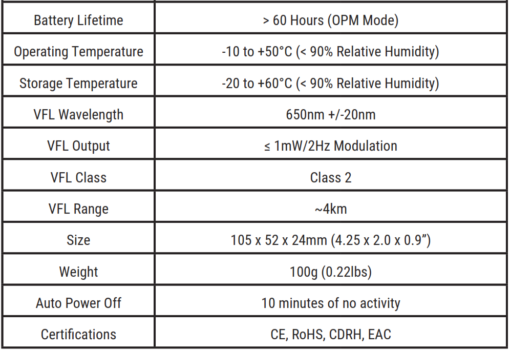
* at -10dBm with FC Connector at 20CSpecifications subject to change without notice.
General Information
This section provides general instructions on how to use the instruments.
Battery
The OPM210 and OPM220 are powered with two AAA alkaline batteries.Do not use rechargeable batteries.When the battery power is low the low battery indicator will be displayed on the LCD.
Auto Power Off
The OPM210/220 will automatically turn off if there are no keypad pushes for approximately 10 minutes with auto power-off enabled.
Press the “Fn” key to turn on the device with auto power off.
Press “Fn” key for two seconds when turning on device, auto power-off will be canceled, LCD displays “PERM”.
Press “Fn” key for two seconds to shut the device off.
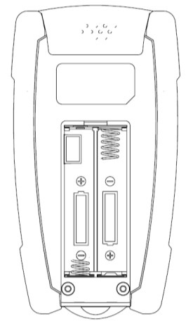
Battery
To replace the batteries, follow these steps:
-
-
- Turn instrument off.
- Remove battery cover.
- Install the new batteries observing correct polarity as below.
-
Connector Interface
Both the OPM and VFL ports are universal 2.5mm. A 1.25mm adapter is available as an optional accessory.
Cleaning the OPM and VFL Interfaces
Make sure that the instrument is powered off. Do not look into the output of any fiber port.Use a new 2.5mm cleaning swab each time to clean each bulkhead port.
-
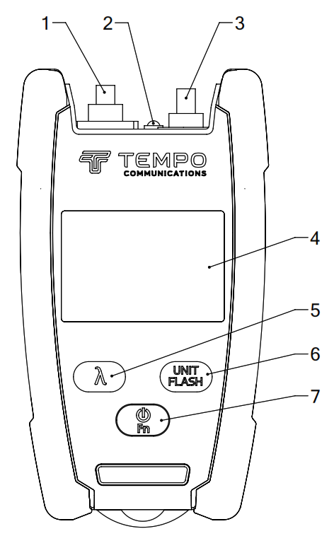
- OPM Connector
- LED Light
- VFL Connector
- LCD
- Set/Ref Set
- OPM Unit Set / Ref Set
- Power on/off and Function
Fn—Function Change
Press the “Fn” key to select OPM or VFL or LED function:

OPM Mode
Press “λ” to select the wavelength. Press “Unit Flash” to change the unit dBm or dB.Press “Unit Flash” for two seconds for REF setting.Press “Unit Flash” and “λ” keys to reference 0dBm.
VFL Mode
Press “Unit Flash” to change output mode, 2Hz modulation or continuous.
LED Mode
Press “Unit Flash” to change from continuous to flash.
![]()
Limited Warranty
Tempo Communications Inc. warrants to the original purchaser of these goods for use that these products will be free from defects in workmanship and material for one year, excepting normal wear and abuse.
For all Test instrument repairs, you must first request a Return Authorization Number by contacting our Customer Service department at: toll-free in the US and Canada 800-642-2155Telephone +1 760 510-0558.Facsimile +1 760 598-9263.This number must be clearly marked on the shipping label. Ship units Freight Prepaid to: Tempo Repair Center, 1390 Aspen Way, Vista, CA 92081 USA.
Mark all packages: Attention: TEST INSTRUMENT REPAIR. For items not covered under warranty (such as dropped, abused, etc.) repair cost quote available upon request.
Note: Prior to returning any test instrument, please check to make sure batteries are fully charged.
Tempo Communications1390 Aspen Way • Vista, CA 92081 • USA800-642-2155
Tempo Europe Ltd. • Brecon House, William BrownClose Cwmbran, NP44 3AB, UK • Tel: +44 1633 927 050www.TempoCom.com
Tempo OPM210/OPM220 Fiber Optic Power Meter User Manual – Tempo OPM210/OPM220 Fiber Optic Power Meter User Manual –
[xyz-ips snippet=”download-snippet”]