Testrix Inspection Camera System User Manual
SAFETY
Warning please read all safety warnings and all instructions before using this product. Neglect to follow the warnings and instructions may result in electrical shock, fire and potential injury.
- Do not expose the inspection camera to any moisture, gases or other material that may cause corrosion.
- Turn off the unit when not in use and store in a dry place .
- Ensure area is clean and well lit.
- Keep children and pets away from the unit while operating.
- This unit is not intended to be used by any person with limited physical, sensory, or mental capabilities.
- Only the camera head and fiberoptic cables are water resist ant.
BATTERY
- Please fully charge the battery for the first time of receiving the unit.
- Charge the device when the power button turns red, red light blinking indicates battery is charging and when the light is off is when battery is full.
- Please charge device at least once every 3 months to prevent any damage to the battery.
![]() Never dispose of used batteries rechargeable Batteries in household waste. As consumers, users ore legally’ required to take used batteries ta appropriate collection sites, the retail sere here the Catteries were purchased, or wherever Catteries are Do not instrument in household waste. The user is seated t’ take end-of-fife devices ta a designated collection point for the disposal of electrical and electronic equipment.
Never dispose of used batteries rechargeable Batteries in household waste. As consumers, users ore legally’ required to take used batteries ta appropriate collection sites, the retail sere here the Catteries were purchased, or wherever Catteries are Do not instrument in household waste. The user is seated t’ take end-of-fife devices ta a designated collection point for the disposal of electrical and electronic equipment.
MAINTENANCE
- Always keep lens clean and dry after every use .
- Should any component need replacement please contact our service agents.
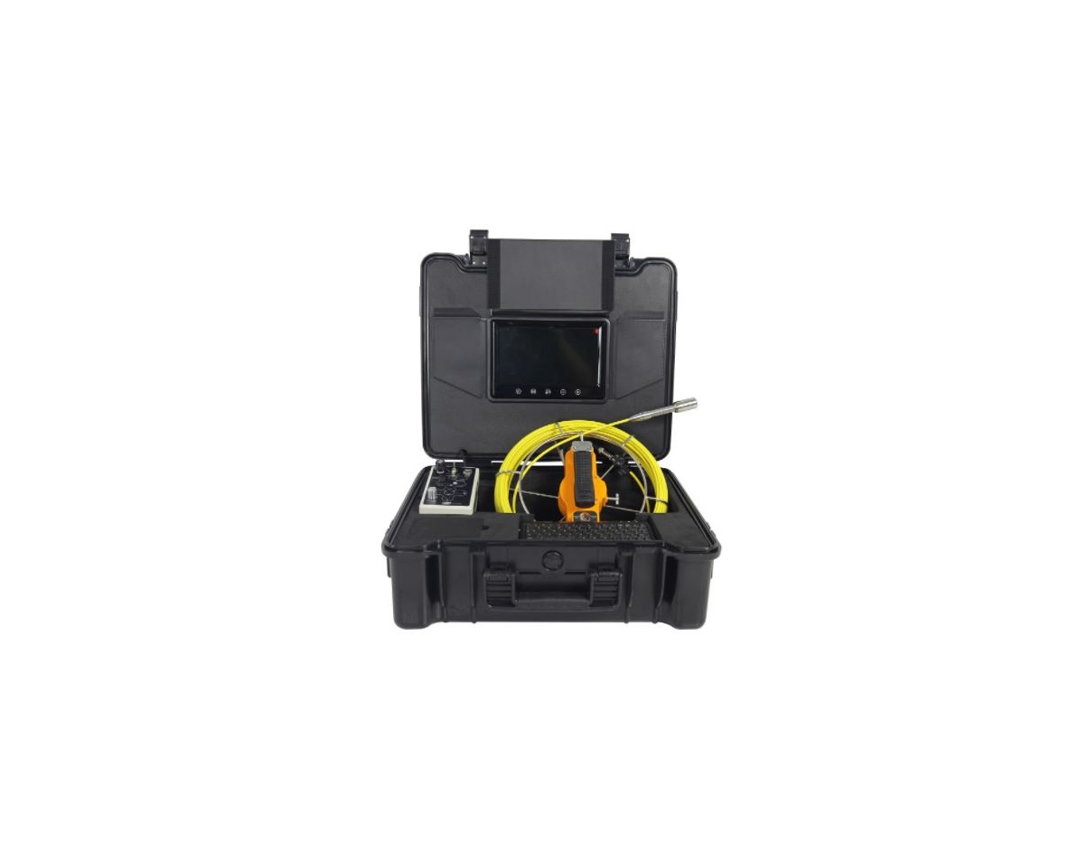
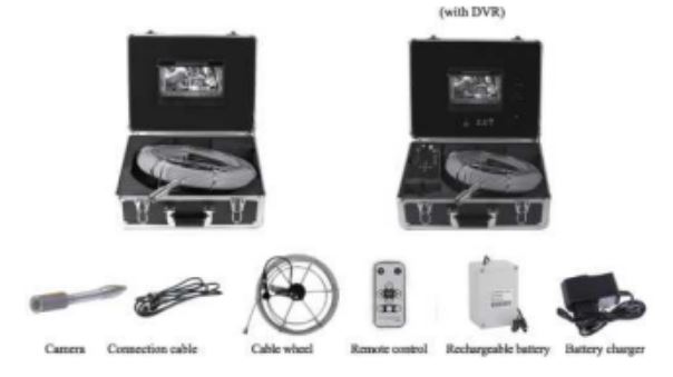
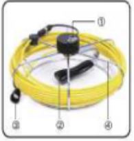
COMPONENTS
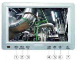
KEY DIAGRAM
7″ TFT LCD Monitor
- AV selector
- Image Flip
- LED ON/ OFF
- Menu
- Menu Up
- Menu Down
- Power Switch
Camera Head
- LED Lights
- Lens
- Spring
- Gold-tip Connector

Push Rod
- Male Plug
- Handle
- Data Connector
- Push Rod Reel
Remote
- Mute
- Power
- AV1/AV2 Switch
- Adjustment –
- Adjustment +
- Menu
- Mode Switch
- Time
- P.P Mode

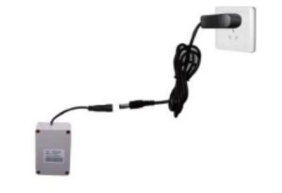
Set-Up
Connection Set-up

Charge Set-up
DVR Diagram
- This DVR unit support SD card up to 16GB.
- Photo Format: JPEG, Resolute ion 720×576
- Video Format: AVI, QVGA {320×240), or Dl{720×480)
Operation

DVR Function
- This DVR function supports up to 16GB.
- Photo Format: JPEG; Resolute ion 720×576
- Video Format; AVI, QVGA {320×240), or Di {720×480)
How to use DVR
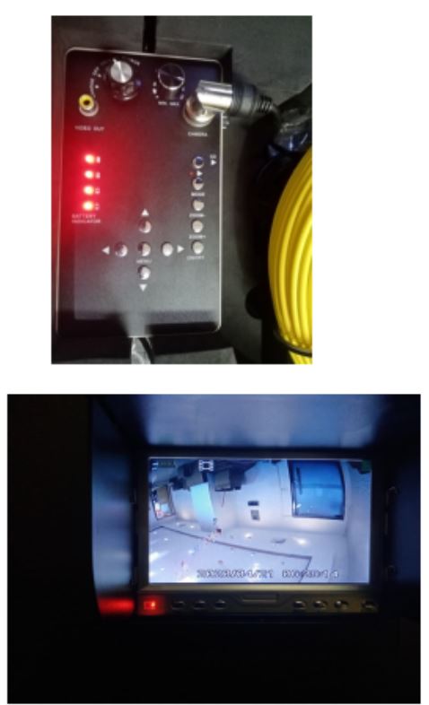
Step 1: Ensure all data cables are properly connected then turn knob to the right to “ON”
Step 2: To record press “SD” and it will st art recording {As shown in picture 1) and to stop recording press “SD” and it will save the recordings {As shown in picture 2)

Questions & Answer
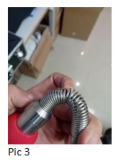
How to resolve the issue where the screen turns completely blue?
- Check to ensure that all data cables are connected correctly and make sure that the camera head is securely tighten.
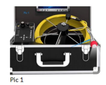
- Check where the cable is broken from inside the spring {Look at picture 3 for guidance)
- Unscrew camera head (pie. 1) and use a microfiber cloth to clean the copper coil (pie. 2); After cleaning, connect data cable then turn on control box afterwards connect the camera head.

How to Release & Coiled Cable
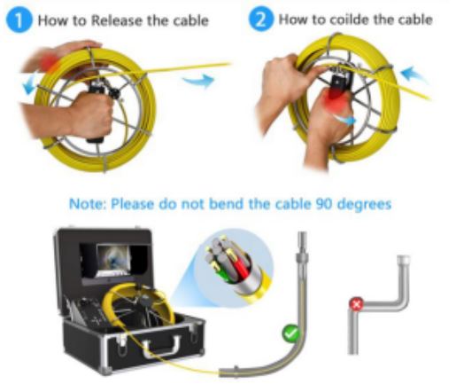
(Note : Keep the cable inside the hook of the pushrod while operating)
Specifications
Image Sensor — CMOSLCD Screen Type — 7″ TFT LCDPixels — l 000TVLHorizontal Viewing Angle — 92 degreesVertical Viewing Angle — 92 degreesCamera Head Diameter— 23mmWaterproof Rating — IP68Power Supply — 12V DCConsumption Current {Max.) — l000mASystem Operating Temp. — -20°C ~ 120°cOperating Humidity {Disp.) — 15 ~85%RHCertification — CE FCC RoHS
For any assistance, please feel free tocontact us at:[email protected]
We also sell replacement parts for any issues with the inspection camera. We will do our best to help solve any issue .Thank you !
[xyz-ips snippet=”download-snippet”]