TEVO Tarantula 3D printer Installation Guide
READ ME FIRST
READ THIS MANUAL COMPLETELY BEFORE ASSEMBLING AND POWERING UP YOUR PRINTER!
Hazards and Warnings
The TEVO Tarantula 3D printer has motorized and heated parts. When the printer is in operation always be aware of possible hazards.
Electric Shock Hazard
Never open the electronics bay of the printer while the printer is powered on. Before removing the access door, always power down the printer and unplug the AC line cord.
Burn Hazard
Never touch the extruder nozzle, heater block, or the heated bed without first turnnig off the hotend (or heated bed) and allowing it to completely cool down. The hotend (or heated bed) can take up to twenty minutes to completely cool down. Also, never touch recently extruded filaments. The filament can stick to your skin and causes burn.
Fire Hazard
Never place flammable materials or liquids on or near the printer when powered on or in operation. Liquid acetone and vapours are extremely flammable.
Pinch Hazard
When the printer is in operation, be careful never to put your fingers in the moving parts, including the belts, pulleys, gears, wheels or leadscrews.
Static Charge
Make sure to ground yourself before touching the printer, especially the electronics Electrostatic charges can damage electronic components. To ground yourself, touch a grounded source.
Age Warning
For user under the ages of 18, adult supervision is recommended. Beware of choking hazards around children.
Letter from TEVO
Dear Customer,Thank you for purchasing the TEVO Tarantula 3D printer.This guide will step you through the assembly and the first run of the printer. If you have any problems during assembly, please go to our Facebook group:https://www.facebook.com/groups/TEVO.3dprinter.owners/If you cannot resolve your problem there, do not hesitate to contact us through the websitehttp://support.tevoprinter.com/Please make sure that the frame is completely square and tight in every angle by using a gemmetrical triangle or any other more sophisticated square tools (not supplied with the printer kit.)Regards,TEVO Team
Assembly
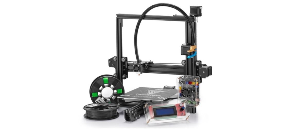
- Remove the parts from the box and remove any tape and padding from the parts. Inspect the parts to make sure they were not damaged in shipment.
- Install the gantry frame (A) to the base frame (B).• On the gantry frame, make sure the nozzle assembly is to the front. On the base frame, make sure the steppeer motor is on the back.• Use the M5x25 screws (4 pcs) and lock washers (4 pcs). Raise the base frame above the table. Install the screws through the base frame into the threaded holes in the gantry frame (as shown in picture below). Tighten with M5 hex key (Allen) wrench.

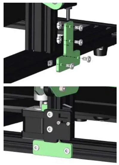
3. Install the two T-shaped frame reinforcement plates. The plate with the limit switch goes on the Z stepper motor side.• Loosen the T-nuts by hand and turn them so they will fit inside the grooves on the frames. Keep the nuts loose so that when you tighten the bolts, the nuts will rotate 90 degress and grab onto the inside of the groove.• Tighten all eight bolts using the M5 hex key (Allen) wrench.
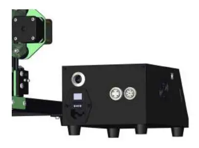
4. Connect all electrical cables.• Put the control box on the lead screw side of the printer with the screen facing forward.• Connect the heater cables to the control box.The cable for the build pates has four pins. The cable for the nozzle heater has eight pins. Rotate the connector until the pins slide easily into the socket. DO NOT force them.After the pins are fully inserted, hand-tighten the knurled nuts so they don’t become unplugged.• Connect the stepper motor and limit switch cables.The Y cables go to the stepper motor and limit switch at the back of the base frame.The Z cables go to the stepper motor and limit switch on the lead screw side of the base frame. The X and E (extruder) cables go to the gantry frame. The X cables go to the stepper motor and limit switch that runs the belt and the E cables go to the stepper motor that drives the extruder.• Connect the power cord to the back of the control box and to a standard 220v/110v electrical outlet.• Turn the power on using the switch on the back of the control box.
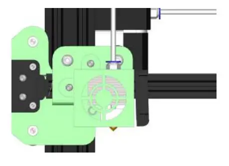
5. Make sure the PTFE tube is all the way down in the hot end, it may come loose during transportation. Push it down all the way into the hotend. Gaps between PTFE tube and nozzle will cause clogging.
Fine-Tuning
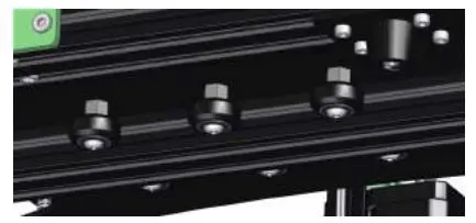
1. Adjust the tension of the build plate wheels on the Y-axis on the base frame.• Check the tension of the build plate wheels. Try to turn the wheels under the build plate without forcing it. If the wheel turns freely or without much effort, then it is too loose.• To tighten the wheels, rotate the eccentric nut that connect to the wheel. Use the open end wrench to rotate the nuts slightly until the wheels is snug against the Y-axis frame.• The build plate assembly and the belt should move forward and backward without much effort, and there should have no side-to-side wiggle or play.
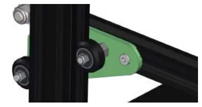
2. Adjust the tension of the gantry wheels on the right pillar of the gantry frame.• Check the tension of the gantry plate wheels. Try to turn the wheels behind the plate without forcing it. If the wheel turns freely or without much effort, it is too loose.• To tighten the wheels, rotate the eccentric nut that connect to the wheel. Use the openend wrench to rotate the nut slightly until the wheel is snug against the Z-axis.
3. Adjust the tension of the X-carriage wheels on the X-axis on the gantry frame.• Check the tension of the X-carriage wheels. Try to turn the wheels under the build plate without forcing it. If the wheel turns freely or without much effort, then it is too loose.• To tighten the wheels, rotate the eccentric nut that connect to the wheel. Use the open end wrench to rotate the nuts slightly until the wheels is snug against the X-axis frame.• The hotend assembly and the belt should move left and right without much effort, and there should have no front-and-back wiggle or play
4. Check the tension of the belt driving the Y-axis (under the build plate). The belt should be taut, with no slack or slop.• If the belt is loose:• Loosen the four bolts at the front of the base frame holding the belt pulley.• Pull the pulley to tighten the belt. Holding the belt taut, tighten the four bolts.
5. Check the tension of the belt driving the X-carriage. The belt should be taut, with no slack or slop.
- If the belt is loose:
- Loosen the two bolts at the right side of the gantry holding the belt pulley.
- Pull the pulley to tighten the belt. Holding the belt taut, tighten the two bolts.
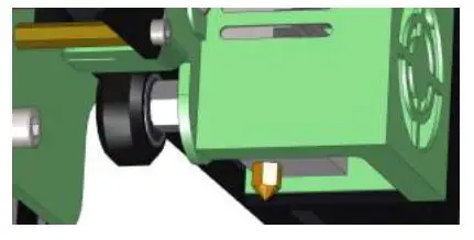
6. Adjust the tension on the Titan Extruder with the screw shown in the picture below if the filament doesn’t come out smoothly during print.
Leveling the Build Plate
To build good parts, the build plate needs to be level, and the nozzle needs to be about 0.1mm from the build plate in all locations. This is about the thickness of a single piece of A4 paper. You want to adjust the height of the build plate so thate you can barely slide the paper between the nozzle and the build plate with only a little resistance.
- Select Prepare -> Preheat PLA. This will heat up the bed and the nozzle to actual printing conditions, making the leveling more accurate.
- Select Prepare -> Auto home. This will move the nozzle to the home position at the front left corner of the build plate.
- Select Prepare -> Disable steppers. This will allow you to move the X-carriage and build plate by hand.
- Tips: The Z-axis stepper motor is also disabled, and you don’t want it to move at all. So you should handle the printer gently during the leveling process. Keep it flat and move the X-carriage carefully.
- Wait for the print bed and nozzle temperature to reach the target temperature. The info screen displays this information below the nozzle and bed icons.
- Slide a piece of paper between the nozzle and the build plate.
- Adust each of the four thumbscrews under the bed until the piece of paper slides, with just a bit of drag, in all locations on the build plate.
- You may need to make fine adjustments to the bed level when you start printing. The first layer of the print will show whether the distance between the nozzle and the build plate is correct. You want it to be pushed into the build surface slightly to maximize surface area contact while still allowing good extrusion flow.• You can try to carefully adjust the thumbscrews during the first layer of the print while the plate is moving until the distance between the nozzle and the build plate is producing smooth extruded lines.• After you have fine-tuned the bed level during the first layer, you may want to stop the print, clear the build plate, and restart the print.
Preparaing Slicing Software
This printer works with most slicing/printing software like Simplify3D, Cura, Repetier-Host, etc. But we will go in details for Repetier-Host software and tell you how to set it up so that you can make your first print. First we recommend you to download the software from the official website: https://www.repetier.com
After installation is done and you start the software, you should get the following screen:
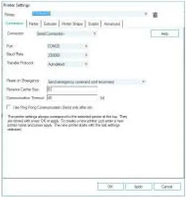
Now we have to set up our printer in the settings so that Repetier-Host can connect to it and will know what size of build area our printer use. Open the Printer Settings window (click Config -> Printer Settings).
First set Port to whatever port your mainboard uses (when you have connected your printer to PC it should show up in here). Set Baud Rate to 250000 and DO NOT touch any other settings in this tab (see picture in next page.)
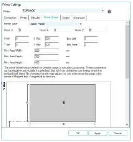
Click on Printer Shape tab, change the following values:X Max – 320Y Max – 320Print Area Width – 300Print Area Depth – 300Print Area Height – 400
Go to Printer tab, change the value according to the picture on the left.

Go to Slicer tab, select Slic3r as slicer and click on Configuration.
On Slic3r window, go to File -> Load Config. (Loaded setting is for general PLA filament printing).Select and load Tornado.ini from SD card.Rename print setting, filament, printer to Tornado and save.
How to Slice 3D Object for SD Print
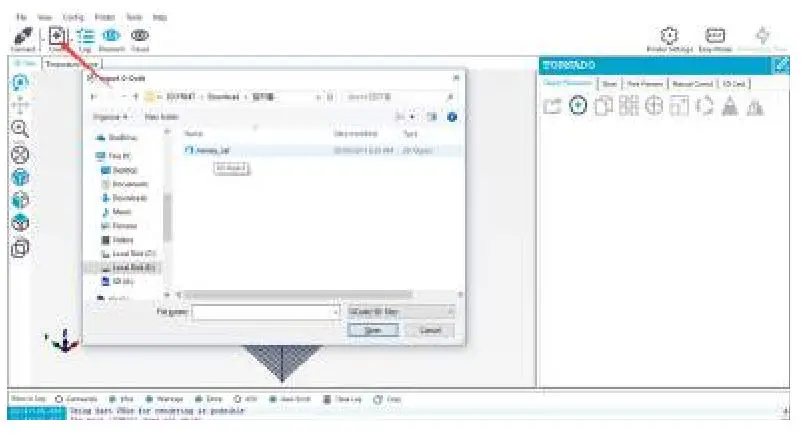
Click on Load, browse to location of the file, then choose Open.
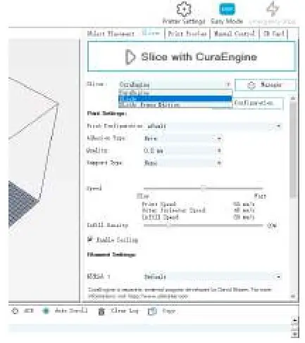
After the file is open up in 3D view, click on Slicer tab to go into slicing page.
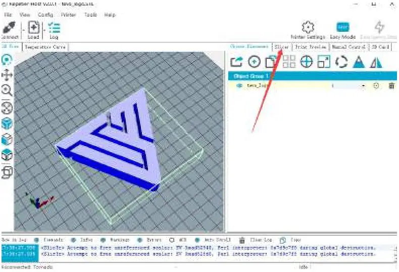 Select the correct Print Setting, Printer Settings, and Extruder type, then click on Slice with Slic3r.
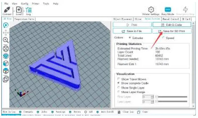
After slicing, click on Save for SD Print to save the G-code file to the SD card with file name of your choice. Then you can insert the card to your printer and choose Print from SD to start printing.
How to Flash Firmware
To install firmware on your printer, you’ll need to download the following:
- Arduino IDE (http://www.arduino.cc)
- Firmware Source Code (You can get it from many ways, e.g. our Facebook Page Files section, our Customer Service, or from Marlin and Repetier directly.)
In this chapter, we’re going to use Marlin for demonstration.
ConfigurationFirmware downloaded from our Facebook page or from our customer service are pre-configured, you can use it without any modification.To configure, you’ll need to edit two files: configuration.h and configuration_adv.h. You can visit their website for explanations of the configuration file format and a synopsis of most of the options in these files.
Verify / CompileTo start the process, do the following steps:
- Double-click Marlin.ino file to open it in Arduino IDE.
- Select Arduino/Genuino Mega or Mega 2560 from Tools -> Boards menu.
- Select the serial (USB) port that your board is connected to in Tools -> Serial Port menu.
- Click the Verify/Compile button at the top of the window to make sure there are no configuration errors. (Or you can click on Upload button next to Verify/Compile if you’re using Marlin from our Facebook page or our customer service).
- Once all errors are fixed, proceed with the upload by clicking Upload button. A blue or green LED on the board will flash rapidly during this process.
Flash Your BoardTo flash your board, do the following steps:
- Ensure Marlin.ino is open in the Arduino IDE.
- Select Arduino/Genuino Mega or Mega 2560 from Tools -> Boards menu.
- Select the serial (USB) port that your board is connected to in Tools -> Serial Port menu.
- Click on Upload button to begin flashing your controller board. A blue or green LED on the board will flash rapidly during this process.
That’s it! Now you’ve flashed firmware to your board, enjoy printing!
TEVO After-Sales
Dear Customer,Thank you for purchasing TEVO 3D printer. We are dedicated to producing low price, high quality 3D printers and hope you have as much fun using it as we did creating it!If you have any issue/questions regarding the contents in the kit, please fill out a Service Ticket on our Support page. http://support.tevoprinter.com
Creating a Service Ticket will serve as your official request for TEVO support. Our Customer Support Team will contact you within 48 hours.
SERVICE INFORMATION:
1. REPLACEMENT PARTS
1.1. TEVO products are covered under a Replacement Part Program for a period of 12 months from the date of purchase.1.2. Missing/Damaged/Defective Parts1.2.1. Within 7 days of the delivery date, TEVO will replace any parts free of charge including shipping fees.1.2.2. After 7 days of the delivery date, TEVO will replace any parts free of charge BUT the customer will be responsible for shipping fees.1.3. Customer Damaged Parts1.3.1. The customer shall pay for the cost of the parts AND the shipping fees.
2. CARRIER LOSS, MIISSING, DAMAGED, AND DEFECTIVE PARTS
2.1. Claims for lost or damaged shipments must be reported to the carrier within the carrier’s claim window, the customer needs to inform TEVO within 7 days of the delivery date.2.1.1. For any parts lost or damaged during shipping, the customer shall take photos or video and submit them when filling out a Service Ticket. If a claim number was issued by the carrier, please include the claim number when creating your Service Ticket (Report a Problem / Carrier Lost Parts.)2.1.2. Once the Carrier dispute is resolved, please provide TEVO with all communications with the carrier. It is the customer’s responsibility to keep TEVO up to date with ALL communications with the carrier.2.1.3. TEVO will work with the customer on replacing the parts in the claim.
2.2. For Missing Parts, refer to section 1.2, the customer shall fill out a Service Ticket (Report a Problem / Missing Parts.)2.3. For Damaged Hardware Parts, refer to section 1.2, the customer shall take photos or video and submit them when filling out a Service Ticket (Report a Problem / Damaged Hardware Parts.)2.4. For Defective Electronic Parts, refer to section 1.2, the customer shall take photos or video and submit them when filling out a Service Ticket (Report a Problem / Defective Electronic Parts.)
2.4.1. If the part is the LCD Panel, Power Supply or Mainboard, the customer shall ship the part back to TEVO and TEVO will send a new part.
2.5. For parts damaged by the customer, refer to section 1.3, submit a Service Ticket (Report a Problem / Customer Damaged Parts.)
3. GENERAL SUPPORT
For information and support on building and operating your TEVO Tornado 3D printer, please visit the TEVO Tornado Owners Group. https://www.facebook.com/groups/TEVO.Tornado.Owners/

 report this ad
![]()
References
[xyz-ips snippet=”download-snippet”]