GWART36S Air Conditioner
Owner’s ManualOriginal Instructions Split Air ConditionerThank you for choosing our product. Please read this Owner’s Manual carefully before operation and retain it for future reference.
GWART36SGWART36S2 GWHART36S2
ContentOperation NoticesPrecautions……………………………………………………………………………………………… 1 Parts name ……………………………………………………………………………………………… 6Screen Operation GuideButtons on remote controller ……………………………………………………………………… 8 Introduction for icons on display screen ……………………………………………………….8 Introduction for buttons on remote controller………………………………………………… 9 Function introduction for combination buttons…………………………………………….. 14 Operation guide ……………………………………………………………………………………… 16 Replacement of batteries in remote controller…………………………………………….. 16 Emergency operation ……………………………………………………………………………… 17MaintenanceClean and maintenance…………………………………………………………………………… 17MalfunctionMalfunction analysis ……………………………………………………………………………….. 20Installation NoticeInstallation dimension diagram ………………………………………………………………….24Safety precautions for installing and relocating the unit …………………………….. 25 Tools for installation………………………………………………………………………………… 26 Selection of installation location ……………………………………………………………….. 26 Requirements for electric connection ………………………………………………………… 27InstallationInstallation of indoor unit………………………………………………………………………….. 28 Installation of outdoor unit ……………………………………………………………………….. 33 Vacuum pumping……………………………………………………………………………………. 36 Leakage detection ………………………………………………………………………………….. 36 Check after installation ……………………………………………………………………………. 37Test and operationTest operation………………………………………………………………………………………… 37AttachmentConfiguration of connection pipe ………………………………………………………………. 38 Pipe expanding method…………………………………………………………………………… 40 Wired Controller(Optional) ………………………………………………………………………..41This appliance is not intended for use by persons (including children) with reduced physical, sensory or mental capabilities or lack of experience and knowledge, unless they have been given supervision or instruction concerning use of the appliance by a person responsible for their safety. Children should be supervised to ensure that they do not play with the appliance. If it needs to install, move or maintain the air conditioner, please contact dealer or local service center to conduct it at first. Air conditioner must be installed, moved or maintained by appointed unit. Otherwise, it may cause serious damage or personal injury or death.
Explanation of Symbols
DANGER
Indicates a hazardous situation that, if not avoided, will result in death or serious injury.
Indicates a hazardous situation that, if not avoided, couldWARNING result in death or serious injury.
CAUTIONNOTICE
Indicates a hazardous situation that, if not avoided, may result in minor or moderate injury.Indicates important but not hazard-related information, used to indicate risk of property damage.
Indicates a hazard that would be assigned a signal word WARNING or CAUTION.
Exception ClausesManufacturer will bear no responsibilities when personal injury or property loss is caused by the following reasons.1.Damage the product due to improper use or misuse of the product; 2.Alter, change, maintain or use the product with other equipment without abidingby the instruction manual of manufacturer; 3.After verification, the defect of product is directly caused by corrosive gas; 4.After verification, defects are due to improper operation during transportation ofproduct;5.Operate, repair, maintain the unit without abiding by instruction manual or related regulations;6.After verification, the problem or dispute is caused by the quality specification or performance of parts and components that produced by other manufacturers;7.The damage is caused by natural calamities, bad using environment or force majeure.
Precautions
WARNING
Operation and MaintenanceThis appliance can be used by children aged from 8 years and above and persons with reduced physical, sensory or mental capabilities or lack of experience and knowledge if they have been given supervision or instruction concerning use of the appliance in a safe way and understand the hazards involved.Children shall not play with the appliance. Cleaning and user maintenance shall not be made by children without supervision. Do not connect air conditioner to multi-purpose socket. Otherwise, it may cause fire hazard. Do disconnect power supply when cleaning air conditioner. Otherwise, it may cause electric shock. If the supply cord is damaged, it must be replaced by the manufacturer, its service agent or similarly qualified persons in order to avoid a hazard.Do not wash the air conditioner with water to avoid electric shock. Do not spray water on indoor unit. It may cause electric shock or malfunction.After removing the filter, do not touch fins to avoid injury.Do not use fire or hair dryer to dry the filter to avoid deformation or fire hazard.
1
Precautions
WARNING
Maintenance must be performed by qualified professionals. Otherwise, it may cause personal injury or damage.Do not repair air conditioner by yourself. It may cause electric shock or damage. Please contact dealer when you need to repair air conditioner.Do not extend fingers or objects into air inlet or air outlet. It may cause personal injury or damage.Do not block air outlet or air inlet. It may cause malfunction.Do not spill water on the remote controller, otherwise the remote controller may be broken. When below phenomenon occurs, please turn off air conditioner and disconnect power immediately, and then contact the dealer or qualified professionals for service.Power cord is overheating or damaged. There’s abnormal sound during operation. Circuit break trips off frequently. Air conditioner gives off burning smell. Indoor unit is leaking.If the air conditioner operates under abnormal conditions, it may cause malfunction, electric shock or fire hazard.When turning on or turning off the unit by emergency operation switch, please press this switch with an insulating object other than metal.Do not step on top panel of outdoor unit, or put heavy objects. It may cause damage or personal injury.
2
PrecautionsWARNINGAttachment Installation must be performed by qualified professionals. Otherwise, it may cause personal injury or damage. Must follow the electric safety regulations when installing the unit. According to the local safety regulations, use qualified power supply circuit and circuit break. Do install the circuit break. If not, it may cause malfunction. An all-pole disconnection switch having a contact separation of at least 3mm in all poles should be connected in fixed wiring. Including an circuit break with suitable capacity, please note the following table. Air switch should be included magnet buckle and heating buckle function, it can protect the circuit-short and overload. Air Conditioner should be properly grounded. Incorrect grounding may cause electric shock. Don’t use unqualified power cord. Make sure the power supply matches with the requirement of air conditioner. Unstable power supply or incorrect wiring may result in electric shock, fire hazard or malfunction. Please install proper power supply cables before using the air conditioner. Properly connect the live wire, neutral wire and grounding wire of power socket. Be sure to cut off the power supply before proceeding any work related to electricity and safety.3
PrecautionsWARNINGDo not put through the power before finishing installation. If the supply cord is damaged, it must be replaced by the manufacturer, its service agent or similarly qualified persons in order to avoid a hazard. The temperature of refrigerant circuit will be high, please keep the interconnection cable away from the copper tube. The appliance shall be installed in accordance with national wiring regulations. Installation must be performed in accordance with the requirement of NEC and CEC by authorized personnel only. The air conditioner is the first class electric appliance. It must be properly grounding with specialized grounding device by a professional. Please make sure it is always grounded effectively, otherwise it may cause electric shock.The yellow-green wire in air conditioner is grounding wire, which can’t be used for other purposes.The grounding resistance should comply with national electric safety regulations.The appliance must be positioned so that the plug is accessible. All wires of indoor unit and outdoor unit should be connected by a professional. If the length of power connection wire is insufficient, please contact the supplier for a new one. Avoid extending the wire by yourself.4
Precautions
WARNING
For the air conditioner with plug, the plug should be reachable after finishing installation.For the air conditioner without plug, an circuit break must be installed in the line.If you need to relocate the air conditioner to another place, only the qualified person can perform the work. Otherwise, it may cause personal injury or damage.Select a location which is out of reach for children and far away from animals or plants. If it is unavoidable, please add the fence for safety purpose.The indoor unit should be installed close to the wall.Instructions for installation and use of this product are provided by the manufacturer.
Working temperature range
Maximum cooling Maximum heating
Indoor side DB/WB(/°F) Outdoor side DB/WB(/°F)
27/19(81/66)
46/24(115/75)
27/-(81/-)
24/18(75/64)
NOTICE:
The operating temperature range (outdoor temperature) for cooling only unit is -15 ~ 46(5 ~ 115°F) ; for heat pump unit is -20~ 46(-4 ~ 115°F).
5
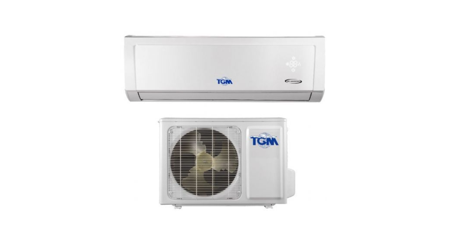
Parts nameIndoor Unit
air inlet panelaux.buttonhorizontal louver air outlet
(Display content or position may be different from above graphics, please refer to actual products)
remote controller
Outdoor Unit
air inlet
Connection wire
air outletNOTICE:Actual product may be different from above graphics, please refer to actual products.6
Parts name
DisplayFor some models:cooling power indicator indicator
receiver window
heating indicator
temp. indicator
drying indicator
display
For some models: temp.indicator heating indicatorcooling indicatorpower indicatordrying indicator
displayreceiver window
For some models:heating indicatorcooling indicator
drying indicatortemp. indicator power indicatorreceiver window
For some models:Power indicator
temp. indicator
display
For some models: display
receiver window
temp. indicator receiver windowWRGFor some models: display
Power LED color indicator: Green-status-ON. Red -status-OFF.Mode LED color indicator: White-W-Cool Mode-WRed-R-Heat Mode- (only for heating model) RGreen-G-Dry Mode- G
temp. indicatorreceiver window
Power LED color indicator: Green-status-ON. Red -status-OFF.
Mode LED color indicator:
WRO
White-W-Cool ModeWRed-R-Heat Mode- (only for heating model) ROrange-O-Dry Mode- O
Display content or position may be different from above graphics, please refer to actual products.
7
Buttons on remote controller
1 ON/OFF button
2 MODE button
3 FAN button
4 TURBO button
5 / button
6 button
1
7 button
8 T-ON / T-OFF button
2
9 I FEEL button
4
3
10 CLOCK button
5
11 SLEEP button
7
6
12 X-FAN button (Note: X-FAN is the same with BLOW.)
9
8
13
button
13
10
14 LIGHT button
14
11 15 TEMP button
15
12
Introduction for icons on display screen
Operation modeAuto mode Cool modeDry mode Fan mode Heat modeClock T-ON /T-OFFSet time Quiet
{ Set fan speed
(No
a
fan speed. It’s displayed
only after turning it on.)
Send signal
{ WiFi
This is a general remote controller.Some models have this function while some
do not. Please refer to the actual models.
Switch temperature displaying type on
the unit’s display
8 heating function
I feel Child lock Sleep mode Turbo modeLeft & right swing Up & down swingHealthy mode Scavenging function X-FAN function
8
Introduction for buttons on remote controllerNote:This is a general use remote controller, it could be used for the air conditioners with multifunction; For some function, which the model doesn’t have, if press the corresponding button on the remote controller that the unit will keep the original running status.After putting through the power, the air conditioner will give out a sound. Operation indicator ” ” is ON (red indicator, the colour is different for different models). After that, you can operate the air conditioner by using remote controller.Under on status, pressing the button on the remote controller, the signal icon ” ” on the display of remote controller will blink once and the air conditioner will give out a “di” sound, which means the signal has been sent to the air conditioner.1 ON/OFF buttonPress this button to turn on the unit. Press this button again to turn off the unit.2 MODE buttonPress this button to select your required operation mode.AUTO COOL DRY FAN HEATWhen selecting auto mode, air conditioner will operate automatically according to ex-factory setting. Set temperature can’t be adjusted and will not be displayed as well. Press “FAN” button can adjust fan speed. Press ” ” / ” ” button can adjust fan blowing angle.After selecting cool mode, air conditioner will operate under cool mode. Cool indicator ” ” on indoor unit is ON. (This indicator is not available for some models.) Press “” or ” ” button to adjust set temperature. Press “FAN” button to adjust fan speeFd. Press ” ” / ” ” button to adjust fan blowing angle.When selecting dry mode, the air conditioner operates at low speed under dry mode. Dry indicator ” ” on indoor unit is ON. (This indicator is not available for some models.) Under dry mode, fan speed can’t be adjusted. Press ” ” / ” ” button to adjust fan blowing angle.When selecting fan mode, the air conditioner will only blow fan, no cooling and no heating. All indicators are OFF. Press “FAN” button to adjust fan speed. Press ” ” / ” ” button to adjust fan blowing angle.When selecting heating mode, the air conditioner operates under heat mode. Heat indicator ” ” on indoor unit is ON. (This indicator is not available for some models.) Press “” or ” ” button to adjust set temperature. Press “FAN” button to adjust fan speed. Press ” ” / ” ” button to adjust fan blowing angle. (Cooling only unit won’t receive heating mode signal. If setting heat mode with remote controller, press ON/OFF button can’t start up the unit).9
Introduction for buttons on remote controllerNote:For preventing cold air, after starting up heating mode, indoor unit will delay 1~5 minutes to blow air (actual delay time is depend on indoor ambient temperature).Set temperature range from remote controller: 16~30 (61-86°F); Fan speed: auto, low speed, low-medium speed,medium speed, medium-high speed,high speed.3 FAN buttonPressing this button can set fan speed circularly as: auto (AUTO), low( ), medium ( ), high( ).AutoNote:Under AUTO speed, air conditioner will select proper fan speed automatically according to ex-factory setting.It’s Low fan speed under Dry mode.4 TURBO buttonUnder COOL or HEAT mode, press this button to turn to quick COOL or quick HEAT mode. ” ” icon is displayed on remote controller. Press this button again to exit turbo function and ” ” icon will disappear. If start this function, the unit will run at super-high fan speed to cool or heat quickly so that the ambient temp. approachs the preset temp. as soon as possible.5 / buttonPress “” or ” ” button once increase or decrease set temperature 1 (°F). Holding “” or ” ” button, 2s later, set temperature on remote controller will change quickly. On releasing button after setting is finished, temperature indicator on indoor unit will change accordingly. (Temperature can’t be adjusted under auto mode)When setting T-ON, T-OFF or CLOCK, press “” or ” ” button to adjust time. (Refer to CLOCK, T-ON, T-OFF buttons)10
Introduction for buttons on remote controller
6
button
Press this button can select left & right swing angle. Fan blow angle can be selected
circularly as below:
Note:
no display (stops at current position)
Press this button continuously more than 2s, the main unit will swing back and
forth from left to right, and then loosen the button, the unit will stop swinging and
present position of guide louver will be kept immediately.
Under swing left and right mode, when the status is switched from off to , if
press this button again 2s later, status will switch to off status directly; if press
this button again within 2s, the change of swing status will also depend on the
circulation sequence stated above.
7
button
Press this button can select up & down swing angle. Fan blow angle can be selected circularly as below:
no display (horizontal louvers stops at current position)When selecting ” “, air conditioner is blowing fan automatically. Horizontal louver will automatically swing up & down at maximum angle.When selecting ” “, air conditioner is blowing fan at fixed position. Horizontal louver will stop at the fixed position.When selecting ” “, air conditioner is blowing fan at fixed angle. Horizontal louver will send air at the fixed angle.Hold ” ” button above 2s to set your required swing angle. When reaching your required angle, release the button.Note:” ” may not be available. When air conditioner receives this signal, the air conditioner will blow fan automatically.Press this button continuously more than 2s, the main unit will swing back and forth from up to down, and then loosen the button, the unit will stop swinging and present position of guide louver will be kept immediately.Under swing up and down mode, when the status is switched from off to , if press this button again 2s later, status will switch to off status directly; if pressthis button again within 2s, the change of swing status will also depend on the circulation sequence stated above.
11
Introduction for buttons on remote controller8 T-ON / T-OFF buttonT-ON button “T-ON” button can set the time for timer on. After pressing this button, ” ” icon disappears and the word “ON” on remote controller blinks. Press “” or ” ” button to adjust T-ON setting. After each pressing “” or ” ” button, T-ON setting will increase or decrease 1min. Hold “” or ” ” button, 2s later, the time will change quickly until reaching your required time. Press “T-ON” to confirm it. The word “ON” will stop blinking. ” ” icon resumes displaying. Cancel T-ON: Under the condition that T-ON is started up, press “T-ON” button to cancel it.T-OFF button “T-OFF” button can set the time for timer off. After pressing this button,” ” icon disappears and the word “OFF” on remote controller blinks. Press “” or ” ” button to adjust T-OFF setting. After each pressing “” or ” ” button, T-OFF setting will increase or decrease 1min. Hold “” or ” ” button, 2s later, the time will change quickly until reaching your required time. Press “T-OFF” word “OFF” will stop blinking. ” ” icon resumes displaying. Cancel T-OFF. Under the condition that T-OFF is started up, press “T-OFF” button to cancel it.Note:Under on and off status, you can set T-OFF or T-ON simultaneously. Before setting T-ON or T-OFF, please adjust the clock time. After starting up T-ON or T-OFF, set the constant circulating valid.After that, air conditioner will be turned on or turned off according to setting time. ON/OFF button has no effect on setting. If you don’t need this function, please use remote controller to cancel it.9 I FEEL buttonPress this button to start I FEEL function and ” ” will be displayed on the remote controller. After this function is set, the remote controller will send the detected ambient temperature to the controller and the unit will automatically adjust the indoor temperature according to the detected temperature. Press this button again to close I FEEL function and ” ” will disappear. Please put the remote controller near user when this function is set. Do not putthe remote controller near the object of high temperature or low temperature in order to avoid detecting inaccurate ambient temperature.12
Introduction for buttons on remote controller10 CLOCK buttonPress this button to set clock time. ” ” icon on remote controller will blink. Press “” or ” ” button within 5s to set clock time. Each pressing of “” or ” ” button, clock time will increase or decrease 1 minute. If hold “” or ” ” button, 2s later, time will change quickly. Release this button when reaching your required time.
Note:Clock time adopts 24-hour mode. The interval between two operations can’t exceeds 5s. Otherwise, remote contro-ller will quit setting status. Operation for T-ON/T-OFF is the same.
11 SLEEP buttonUnder COOL, or HEAT mode, press this button to start up sleep function. ” ” icon is displayed on remote controller. Press this button again to cancel sleep function and ” ” icon will disappear.After powered on, Sleep Off is defaulted. After the unit is turned off, the Sleep function is canceled. In this mode, the time of time can be adjusted. Under FanaDRY and Auto modes, this function is not available.
12 X-FAN buttonPressing this button in COOL or DRY mode, the icon ” ” is displayed and the indoor fan will continue operation for a few minutes in order to dry the indoor unit even though you have turned off the unit. After energization, X-FAN OFF is defaulted.X-FAN is not available in AUTO, FAN or HEAT mode. This function indicates that moisture on evaporator of indoor unit will be blowed after the unit is stopped to avoid mould. Having set X-FAN function on: After turning off the unit by pressing ON/OFFbutton indoor fan will continue running for about a few minutes. at low speed. In this period, press X-FAN button to stop indoor fan directly. Having set X-FAN function off: After turning off the unit by pressing ON/OFF button, the complete unit will be off directly.
13
button
Press this button to achieve the on and off of healthy and scavenging functions in
LCD displays ” “. Press the button for the second time to start healthy and scavenging functions simultaneously; LCD displays ” ” and ” “. Press this button for the third time to quit healthy and scavenging functions simultaneously. Press the button for the fourth t ime to start healthy function; LCD display ” “. Press this button again to repeat the operation above.This function is applicable to partial of models.13
Introduction for buttons on remote controller14 LIGHT buttonPress this button to turn off display light on indoor unit. ” ” icon on remote controller disappears. Press this button again to turn on display light. ” ” icon is displayed.15 TEMP buttonBy pressing this button, you can see indoor set temperature, indoor ambient temperature or outdoor ambient temperature on indoor unit’s display. The setting on remote controlleris selected circularly as below:no displayWhen selecting ” ” or no display with remote controller, temperature indicator on indoor unit displays set temperature.When selecting ” ” with remote controller, temperature indicator on indoor unit displays indoor ambient temperature.When selecting ” ” with remote controller, temperature indicator on indoor unit displays outdoor ambient temperature.Note:Outdoor temperature display is not available for some models. At that time, indoor unit receives ” ” signal, while it displays indoor set temperature.It’s defaulted to display set temperature when turning on the unit.There is no display in the remote controller.Only for the models whose indoor unit has dual-8 display. When selecting displaying of indoor or outdoor ambient temperature, indoortemperature indicator displays corresponding temperature and automatically turnFunction introduction for combination buttonsEnergy-saving functionUnder cooling mode, press “TEMP” and ” CLOCK” buttons simultaneously to start up or turn off energy-saving function. When energy-saving function is started up, “SE” will be shown on remote controller, and air conditioner will adjust the set temperature automatically according to ex-factory setting to reach to the best energy-saving effect. Press “TEMP” and “CLOCK” buttons simultaneously again to exit energy-saving function.Note:Under energy-saving function, fan speed is defaulted at auto speed and it can’t14
Function introduction for combination buttonsbe adjusted. Under energy-saving function, set temperature can’t be adjusted. Press “TURBO”button and the remote controller won’t send signal. Sleep function and energy-saving function can’t operate at the same time. Ifenergy-saving function has been set under cooling mode, press sleep button will cancel energy-saving function. If sleep function has been set under cooling mode, start up the energy-saving function will cancel sleep function.8 heating functionUnder heating mode, press “TEMP” and “CLOCK” buttons simultaneously to start up or turn off 8 heating function. When this function is started up, ” ” and “8 ” will be shown on remote controller, and the air conditioner keep the heating status at 8 . Press “TEMP” and “CLOCK” buttons simultaneously again to exit 8 heating function.Note:Under 8 heating function, fan speed is defaulted at auto speed and it can’t be adjusted.Under 8 heating function, set temperature can’t be adjusted. Press “TURBO” button and the remote controller won’t send signal.Sleep function and 8 heating function can’t operate at the same time. If 8 heating function has been set under heating mode, press sleep button will cancel 8 heating function. If sleep function has been set under heating mode, start up the 8 heating function will cancel sleep function.Under temperature display, the remote controller will display 46 heating.Child lock functionPress “” and ” ” simultaneously to turn on or turn off child lock function. When child lock function is on, ” ” icon is displayed on remote controller. If you operate the remote controller, the ” ” icon will blink three times without sending signal to the unit.Temperature display switchover functionUnder OFF status, press ” ” and “MODE” buttons simultaneously to switch temperature display between and .WIFI FunctionPress “MODE” and “TURBO” button simultaneously to turn on or turn off WIFI function. When WIFI function is turned on, the ” ” icon will be displayed on remote controller; Long press “MODE” and “TURBO” buttons simultaneously for 10s, remote controller will send WIFI reset code and then the WIFI function will be turned on. WIFI function is defaulted ON after energization of the remote controller. This function is only available for some models.15
Operation guide1. After putting through the power, press “ON/OFF” button on remote controller toturn on the air conditioner.2. Press “MODE” button to select your required mode: AUTO, COOL, DRY, FAN,HEAT.3. Press “” or ” ” button to set your required temperature. (Temperature can’tbe adjusted under auto mode).4. Press “FAN” button to set your required fan speed: auto, low speed, low-mediumspeed,medium speed, medium-high speed,high speed.5. Press ” ” button to select fan blowing angle.Replacement of batteries in remote controller1. Lift the cover along the direction of arrow (as shown in Fig 1 ). 2. Take out the original batteries (as shown in Fig 1 ). 3. Place two 7# (AAA 1.5V) dry batteries, and make sure the position of “+”polar and “-” polar is correct (as shown in Fig 2). 4. Reinstall the cover (as shown in Fig 2 ).
Fig.1
Fig.2
NOTICEDuring operation, point the remote control signal sender at the receiving window on indoor unit.The distance between signal sender and receiving window should be no more than 8m, and there should be no obstacles between them.Signal may be interfered easily in the room where there is fluorescent lamp or wireless telephone; remote controller should be close to indoor unit during operation.Replace new batteries of the same model when replacement is required. When you don’t use remote controller for a long time, please take out thebatteries. If the display on remote controller is fuzzy or there’s no display, pleasereplace batteries.16
Emergency operation
If remote controller is lost or damaged, please use aux. button to turn on or turn off the air conditioner. The operation in details is as below:
air conditioner. When the air conditioner is turned on, it will operate under auto mode.
panel
aux. button
WARNING:Use insulated object to press the auto buttonClean and MaintenanceWARNINGTurn off the air conditioner and disconnect the power before cleaning the air conditioner to avoid electric shock.Do not wash the air conditioner with water to avoid electric shock. Do not use volatile liquid to clean the air conditioner. Do not use liquid or corrosive detergent clean the appliance and do not splashwater or other liquid onto it, otherwise, it may damage the plastic components, even cause electric shock.Clean surface of indoor unitWhen the surface of indoor unit is dirty, it is recommended to use a soft dry cloth or wet cloth to wipe it.NOTICE:Do not remove the panel when cleaning it.17
Clean and maintenance
1 Open panel Pull out the panel to a certain
3 Use dust catcher or water to
the water (below 45 (113°F)) to clean it, and then put it in a shady and cool place to dry.
24panel cover tightly.
WARNINGoperation environment, clean frequency can be increased.
18
Clean and maintenanceNOTICE: Checking before use-season1. Check whether air inlets and air outlets are blocked. 2. Check whether circuit break, plug and socket are in good condition. 4. Check whether mounting bracket for outdoor unit is damaged or corroded.If yes, please contact dealer. 5. Check whether drainage pipe is damaged.NOTICE: Checking after use-season1. Disconnect power supply. 3. Check whether mounting bracket for outdoor unit is damaged or corroded.If yes, please contact dealer.Notice for recovery1. Many packing materials are recyclable materials. Please dispose them in appropriate recycling unit.2. If you want to dispose the air conditioner, please contact local dealer or consultant service center for the correct disposal method.19
Malfunction analysisGeneral phenomenon analysisPlease check below items before asking for maintenance. If the malfunction still
Phenomenon
Check items
Solution
Whether it’s interfered severely Pull out the plug. Reinsert (such as static electricity,stable the plug after about 3min, and
voltage)?
then turn on the unit again.
Whether remote controller is within the signal receivingrange?
Signal receiving range is 8m.
Indoor unit Whether there are obstacles?
can’t receive Whether remote controller is
remote
pointing at the receiving
controller’s window?
signal or remote controller has no
Is sensitivity of remote controller low; fuzzy display and nodisplay?
action.
No display when operating
remote controller?
Remove obstacles.Select proper angle and point the remote controller at the receiving window on indoor unit.Check the batteries. If the power of batteries is too low, please replace them.Check whether remote controller appears to be damaged. If yes, replace it.
Fluorescent lamp in room?
Take the remote controller close to indoor unit.
Turn off the fluorescent lamp and then try it again.
No air emitted from indoor unit
Air inlet or air outlet of indoor unit is blocked?Under heating mode, indoor temperature is reached to set temperature?
Eliminate obstacles.After reaching to set temperature, indoor unit will stop blowing out air.
Heating mode is turned on just In order to prevent blowing
now?
out cold air, indoor unit will be
started after delaying for sev-
eral minutes, which is a nor-
mal phenomenon.
20
Malfunction analysis
Phenomenon
Check items
Solution
Air conditioner can’t operate
Power failure?
Wait until power recovery.
Is plug loose?
Reinsert the plug.
Circuit break trips off or fuse is burnt out?Wiring has malfunction?
Ask professional to replace circuit break or fuse.Ask professional to replace it.
Unit has restarted immediately after stopping operation?
Wait for 3min, and then turn on the unit again.
Whether the function setting for remote controller is correct?
Reset the function.
Mist is emitted from indoor unit’s air outlet
Indoor temperature and humidity is high?
Because indoor air is cooled rapidly. After a while, indoor temperature and humidity will be decrease and mist will disappear.
Set temperature can’t be adjusted
Unit is operating under auto mode?Your required temperature exceeds the set temperature range?
Temperature can’t be adjusted under auto mode. Please switch the operation mode if you need to adjust temperature.Set temperature range: 16 ~30 .
Cooling (heating) effect is not good.
Voltage is too low?Filter is dirty? Set temperature is in properrange?Door and window are open?
Wait until the voltage resumes normal.Adjust temperature to proper range.Close door and window.
21
Malfunction analysis
Phenomenon
Check items
Solution
Odours are emitted
Whether there’s odour source, Eliminate the odour source. such as furniture and cigarette, etc.
Air conditio- Whether there’s interference, ner operates such as thunder, wirelessabnormally devices, etc.
Disconnect power, put back power, and then turn on theunit again.
Outdoor unit has vapor
Heating mode is turned on?
During defrosting under heating mode, it may generate vapor, which is a normal phenomenon.
“Water noise
Air conditioner is turned on or turned off just now?
The noise is the sound ofthe unit, which is a normal phenomenon.
Cracking noise
Air conditioner is turned on or turned off just now?
This is the sound of friction caused by expansion and/or contraction of panel or other parts due to the change of temperature.
22
Malfunction analysisError CodeWhen air conditioner status is abnormal, temperature indicator on indoor unit will
ation of error code. Error code
Indoor display
Above indicator diagram is only for reference. Please refer to actual product for the actual indicator and position.
Error code
Troubleshooting
H1(HOeNa1tin0gs OinFdFica0t.o5rs) Means defrosting status. It’s the normal phenomenon. It can be eliminated after restarting the unit. If not, pleaseE5
H6
It can be eliminated after restarting the unit. If not, please
C5
F1
F2
E6
It can be eliminated after restarting the unit. If not, please contact qualified professionals for service.
F0
service.WARNINGWhen below phenomenon occurs, please turn off air conditioner and discon-for service. Power cord is overheating or damaged. There’s abnormal sound during operation. Circuit break trips off frequently. Air conditioner gives off burning smell. Indoor unit is leaking.
If the air conditioner operates under abnormal conditions, it may cause
23
Space to the ceiling At least 15cm At least 250cm
Installation dimension diagram
At least 15cm Space to the wall
At Space
tloeathset 3o0b0sctrmuction
Space to the wall At least 15cm
2000cm50cm Above30cm Above
Space to the obstruction
30cm Above
Space to the wall
Above
Air outlet side
24
Air inlet side50cmAboveSpace to the wall Drainage pipe
Safety precautions for installing and relocating the unitTo ensure safety, please be mindful of the following precautions.WarningWhen installing or relocating the unit, be sure to keep the refrigerant circuit free from air or substances other than the specified refrigerant. Any presence of air or other foreign substance in the refrigerant circuit will cause system pressure rise or compressor rupture, resulting in injury.When installing or moving this unit, do not charge the refrigerant which is not comply with that on the nameplate or unqualified refrigerant. Otherwise, it may cause abnormal operation, wrong action, mechanical malfunction or even series safety accident.When refrigerant needs to be recovered during relocating or repairing the unit, be sure that the unit is running in cooling mode.Then, fully close the valve at high pressure side (liquid valve).About 30-40 seconds later, fully close the valve at low pressure side (gas valve), immediately stop the unit and disconnect power. Please note that the time for refrigerant recovery should not exceed 1 minute. If refrigerant recovery takes too much time, air may be sucked in and cause pressure rise or compressor rupture, resulting in injury.During refrigerant recovery, make sure that liquid valve and gas valve are fully closed and power is disconnected before detaching the connection pipe. If compressor starts running when stop valve is open and connection pipe is not yet connected, air will be sucked in and cause pressure rise or compressor rupture, resulting in injury.When installing the unit, make sure that connection pipe is securely connected before the compressor starts running. If compressor starts running when stop valve is open and connection pipe is not yet connected, air will be sucked in and cause pressure rise or compressor rupture, resulting in injury.Prohibit installing the unit at the place where there may be leaked corrosive gas or flammable gas. If there leaked gas around the unit, it may cause explosion and other accidents.Do not use extension cords for electrical connections. If the electric wire is not long enough, please contact a local service center authorized and ask for a proper electric wire. Poor connections may lead to electric shock or fire.Use the specified types of wires for electrical connections between the indoor and outdoor units. Firmly clamp the wires so that their terminals receive no external stresses. Electric wires with insufficient capacity, wrong wire connections and insecure wire terminals may cause electric shock or fire.25
Tools for installation
1 Level meter 4 Drill head
2 Screw driver 5 Pipe expander
3 Impact drill 6 Torque wrench
7 Open-end wrench
8 Pipe cutter
9 Leakage detector
10 Vacuum pump
11 Pressure meter
12 Universal meter
13 Inner hexagon spanner
14 Measuring tape
Note:Please contact the local agent for installation.
Selection of installation location
Basic requirement
Indoor unit
Installing the unit in the following pla- 1. There should be no obstruction near air
ces may cause malfunction. If it is un- inlet and air outlet.
avoidable, please consult the local dealer: 2. Select a location where the condensat-
1.The place with strong heat sources, ion water can be dispersed easily and
, won’t affect other people.
or volatile objects spread in the air. 3. Select a location which is convenient to
2.The place with high-frequency
connect the outdoor unit and near the
devices (such as welding machine, power socket.
medical equipment).
4. Select a location which is out of reach
3.The place near coast area.
for children.
4.The place with oil or fumes in the air. 5. The location should be able to withstand
5.The place with sulfureted gas.
the weight of indoor unit and won’t incr-
6.Other places with special circumstances. ease noise and vibration.
7.The appliance shall not be installed 6. The appliance must be installed 2.5m
in the laundry.
8.It’s not allowed to be installed on the 7. Don’t install the indoor unit right above
unstable or motive base structure (such the electric appliance.
as truck) or in the corrosive environ- 8. Please try your best to keep way from
ment (such as chemical factory).
Outdoor unit1. Select a location where the noise and outflow air emitted by the outdoor unit will not affect neighborhood.2. The location should be well ventilated and dry, in which the outdoor unit won’t be exposed directly to sunlight or strong wind.3. The location should be able to withstand the weight of outdoor unit.4. Make sure that the installation follows the requirement of installation dimension diagram.5. Select a location which is out of reach for children and far away from animals or plants. If it is unavoidable, please add the fence for safety purpose.
26
Requirements for electric connectionSafety precaution1. Must follow the electric safety regulations when installing the unit. circuit break.3. Make sure the power supply matches with the requirement of air conditioner. Unstable power supply or incorrect wiring or malfunction. Please install proper power supply cables before using the air conditioner.4. Properly connect the live wire, neutral wire and grounding wire of power socket. 5. Be sure to cut off the power supply before proceeding any work related toelectricity and safety. 7. If the supply cord is damaged, it must be replaced by the manufacturer, its 8. The temperature of refrigerant circuit will be high, please keep the interconnec-tion cable away from the copper tube. 9. The appliance shall be installed in accordance with national wiring regulations. 10.Installation must be performed in accordance with the requirement of NECand CEC by authorized personnel onlyGrounding requirementgrounding with specialized grounding device by a professional. Please make sure it is always grounded effectively, otherwise it may cause electric shock. 2. The yellow-green wire in air conditioner is grounding wire, which can’t be used for other purposes. 3. The grounding resistance should comply with national electric safety regulations. 4. The appliance must be positioned so that the plug is accessible. 5. An all-pole disconnection switch having a contact separation of at least 3mm in27
Installation of indoor unitStep one: choosing installation location
rm it with the client.
Step two: install wall-mounting frame1. Hang the wall-mounting frame on the wall; adjust it in horizontal position with the
plastic expansion particles in the holes. 3. Fix the wall-mounting frame on the wall with tapping screws (ST4.2X25TA) and.
Step three: open piping hole1. Choose the position of piping hole according to the direction of outlet pipe. The position of piping hole should be a little lower than the wall-mounted frame, shown as below.
WallSpace to the wall above 150mm
Mark in the middle of it
Left 70mmRear piping hole
Level meter
WallSpace to the wall above 150mm
Right 70mm Rear piping hole
2. Open a piping hole with the diameter of 70 on the selected outlet pipe position. In order to drain smoothly, slant the piping hole on the wall slightly downward tothe outdoor side with the gradient of 5-10°.
28
Installation of indoor unit
Note:Pay attention to dust prevention and take relevant safety measures when opening the hole.The plastic expansion particles are not provided and should be bought locally.
Indoor 5-10
outdoor70
Step four: outlet pipe1. The pipe can be led out in the direction of right, rear right, left or rear left.
2. When select leading out the pipe from left or right, please cut off the corresponding hole on the bottom case.
left
right
right
left rear right
rear left
cut off the hole
1. Aim the pipe joint at the corresponding bellmouth.2. Pretighten the union nut with hand.
pipe joint union nut pipe
3. Adjust the torque force by referring to the following sheet. Place the open-end wrench on the pipe joint and place the torque wrench on the union nut. Tighten the union nut with torque wrench.29
Installation of indoor unit
torque wrench indoor pipe
open-end wrench union nutpipe
Hex nut diameter Tightening torque (N.m)
6
15~20
9.52
30~40
12
45~55
16
60~65
19
70~75
4. Wrap the indoor pipe and joint of connection pipe with insulating pipe, and then wrap it with tape.
insulating pipe
Step six: install drain hose1. Connect the drain hose to the outlet pipe of indoor unit. drain hose outlet pipe2. Bind the joint with tape.tapeNote: Add insulating pipe in the indoordrain hose in order to prevent condensation. The plastic expansion particles are not provided.
outlet drain hose pipe drain hoseinsulating pipe
Step seven: connect wire of indoor unitpane1. Open the panel, remove the screw on the wiring cover and then take down the cover.30
screw wiring cover
Installation of indoor unit
2. Make the power connection wire go through the cable-cross hole at the back of indoor unit and then pull it out from the front side.
cable-cross holepower connection wire
3. Remove the wire clip; connect the power connection wire to the wiring terminal
with wire clip.
N(1) 2 3
white black red green
(blue)
(brown) (yellow-
green)
Outdoor unit connection4. Put wiring cover back and then tighten the screw. 5. Close the panel. 6. Install the Conduit assy. 1) Fix the conduit assy on the conduit board and then let the connection wirebetween indoor unit and outdoor unit go through the conduit. 2) Fix the conduit assy on the chassis with 3 screws. Conduit assy consists of conduit, conduit connector and lock nut.(Not thestandard part, which should be purchased by customer.) The length of conduit can be calculated according to the length of connection wire.
connection wire sleeve
Lock nut
Conduit connector
Note:
Cable Cross Plate Conduit
All wires of indoor unit and outdoor unit should be connected by a professional.
for a new one. Avoid extending the wire by yourself.
installation. For the air conditioner without plug, an circuit break must be installed in the line.The circuit break should be all-pole parting and the contact parting distance should be more than 3mm.31
Installation of indoor unit
Step eight: bind up pipe
1. Bind up the connection pipe, power cord and drain hose with the band.
indoor unit
indoor and outdoor power cordgas pipe
connection pipe
drain hose band
band
liquid pipe drain hose
2. Reserve a certain length of drain hose and power cord for installation when binding them. When binding to a certain degree, separate the indoor power and then separate the drain hose.
indoor power cord3. Bind them evenly. 4. The liquid pipe and gas pipe shouldbe bound separately at the end.Note: The power cord and control wirecan’t be crossed or winding. The drain hose should be boundat the bottom.
Step nine: hang the indoor unit1. Put the bound pipes in the wall pipe and then make them pass through the wall hole.2. Hang the indoor unit on the wall-mounting frame. 3. Stuff the gap between pipes and wall hole with sealing gum. 4. Fix the wall pipe.
indoor wall pipe
outdoor sealing gum
upper hook
lower hook of wall-mounting frameNote: Do not bend the drain hose too excessively in order to prevent blocking.32
Installation of outdoor unit
(select it according to the actual installation situation)1. Select installation location according to the house structure. 2. Fix the support of outdoor unit on the selected location with expansion screws.Note:
installing the outdoor unit. Make sure the support can withstand at least four times of the unit weight. The outdoor unit should be installed at least
joint. (for the model with heating tube, the installation height should be no less than 20cm.) For the unit with cooling capacity of 2300W ~5000W, 6 expansion screws are needed; for the unit with cooling capacity of 6000W ~8000W, 8 expansion screws are needed; for the unit with cooling capacity of 10000W ~16000W, 10 expansion screws are needed.
at least 3cm above the floor
Step two: install drain joint (Only for some models)1. Connect the outdoor drain joint into the hole on the chassis, as shown in the picture below.2. Connect the drain hose into the drain vent.NOTE: As for the shape of drainage joint, please refer to the current product. Do not install the drainage joint in the severe cold area. Otherwise,it will be frosted and then cause malfunction.
1. Place the outdoor unit on the support.2. Fix the foot holes of outdoor unit with bolts.foot holes
drain vent Drain hose
chassis outdoor drain joint33
foot holes
Installation of outdoor unit
Step four: connect indoor and outdoor pipes
1. Remove the screw cap of valve and aim the pipe joint at the bellmouth of pipe.
3. Tighten the union nut with torque wrench by referring to the sheet below.
liquid valve
liquid pipe gas pipegas valve
Hex nut diameter
Tightening torque (N.m)
6
15~20
9.52 12
30~40 45~55
16
60~65
19
70~75
2. Pretighten the union nut with hand.
pipe joint
union nut
1. Remove the handle from the outdoor unit. 2. Fasten the power supply cord and the connection cord to the retaining plate usingthe lock nut.(open the knock out holes if necessary) 3. Connect the power supply cord and the connection cord to terminal. 4. Fasten the power supply cord and connection cord with cord clamp. 5. Install the handle.The screws are packed with the terminal board.
lock nut conduit
Finish
N(1) 2 3
green white
red
(yellow- (blue) black (brown)
green)
L1 L2 Gblack white green (brown) (blue) (yellow-green)
L1
L2
Indoor unit connection POWER
34
Installation of outdoor unit2. Fix the power connection wire and signal control wire with wire clip (only for cooling and heating unit). Note:Never cut the power connection wire to prolong or shorten the distance.
Step six: neaten the pipes1. The pipes should be placed along the wall, bent reasonably and hidden possibly. Min. semidiameter of bending the pipe is 10cm.2. If the outdoor unit is higher than the wall hole, you must set a U-shaped curve in the pipe before pipe goes into the room, in order to prevent rain from getting into the room.
wallU-shaped curve drain hose
Note:The through-wall height of drain hose shouldn’t be higher than the outlet pipe hole of indoor unit.the drain hose can’t raise upwards.
Slant the drain hose slightly downwards. The drain hose can’t be
The water outlet can’t be placed in water in order to drain smoothly.The water outlet can’t be placed in water
The drain hose can’t be fluctuant
The drain hose can’t be fluctuant
The water outlet can’t be fluctuant
35
Vacuum pumpingUse vacuum pump
1. Remove the valve caps on
the liquid valve and gas valve and the nut of refrigerant charging vent. 2. Connect the charging hose of piezometer to the refri-
liquid valvegas valve refrigerant charging vent
piezometer Lo Hivalve cap
gerant charging vent of gas nut of refrigerant valve and then connect the charging vent
other charging hose to the vacuum pump.
vacuum pump
3. Open the piezometer completely and operate for 10-15min to check if the
inner hexagon spanner
pressure of piezometer re-
mains in -0.1MPa.
close
4. Close the vacuum pump
open
and maintain this status for
1-2min to check if the pres-
sure of piezometer remains
in -0.1MPa. If the pressure decreases, there may be leakage.
5. Remove the piezometer, open the valve core of liquid valve and gas valve
completely with inner hexagon spanner.
6. Tighten the screw caps of valves and refrigerant charging vent.
7. Reinstall the handle.
Leakage detection1. With leakage detector: Check if there is leakage with leakage detector.2. With soap water: If leakage detector is not available, please use soap water for leakage detection. Apply soap water at the suspected position and keep the soap water for more than 3min. If there are air bubbles coming out of this position, there’s a leakage.
36
Check after installation
Items to be checked
Possible malfunction
Have you done the refrigerant leakage test?
The unit may drop, shake or emit noise.(heating) capacity. It may cause condensation and water dripping.
Is water drained well?
It may cause condensation and water dripping.
Is the voltage of power supply accord-
ing to the voltage marked on the
It may cause malfunction or damaging
nameplate?
the parts.
Is electric wiring and pipeline installed It may cause malfunction or damaging
correctly?
the parts.
Is the unit grounded securely?
It may cause electric leakage.
Does the power cord follow the speci- It may cause malfunction or damaging the parts.
Is there any obstruction in the air inlet
and outlet?
(heating) capacity.
The dust and sundries caused during It may cause malfunction or damaging
installation are removed?
the parts.
The gas valve and liquid valve of connection pipe are open completely?Is the inlet and outlet of piping hole been covered?
(heating) capacity.It may cause insufficient cooling (heating) capacity or waster eletricity.
Test operation1. Preparation of test operationThe client approves the air conditioner. Specify the important notes for air conditioner to the client.2. Method of test operationPut through the power, press ON/OFF button on the remote controller to start operation.Press MODE button to select AUTO, COOL, DRY, FAN and HEAT to check whether the operation is normal or not.If the ambient temperature is lower than 16(61°F) , the air conditioner can’t start cooling.37
Configuration of connection pipe
1. Standard length of connection pipe 5m, 7.5m, 8m.2.Min. length of connection pipe is 3m.
3.Max. length of connection pipe.
Max. length of connection pipe
Unit: m
Cooling capacity
Max. length of connec-tion pipe
Cooling capacity
Max. length of connec-tion pipe
5000Btu/h (1465W)
15
24000Btu/h (7032W)
25
7000Btu/h (2051W)
15
28000Btu/h (8204W)
30
9000Btu/h (2637W)
15
36000Btu/h (10548W)
30
12000Btu/h (3516W)
20
42000Btu/h (12306W)
30
18000Btu/h (5274W)
25
48000Btu/h (14064W)
30
4. The additional refrigerant oil and refrigerant charging required after prolonging connection pipe After the length of connection pipe is prolonged for 10m at the basis of standard length, you should add 5ml of refrigerant oil for each additional 5m of connection pipe. The calculation method of additional refrigerant charging amount (on the basis of liquid pipe):Additional refrigerant charging amount = prolonged length of liquid pipe × additional refrigerant charging amount per meterBasing on the length of standard pipe, add refrigerant according to the requirement as shown in the table. The additional refrigerant charging amount per meter is different according to the diameter of liquid pipe. See the following sheet.
38
Configuration of connection pipe
Additional refrigerant charging amount for R22, R407C, R410A and R134a
Diameter of connection pipe
Outdoor unit throttle
Liquid pipe(mm) Gas pipe(mm) Cooling only(g/m) Cooling and heating(g/m)
6
9.52 or 12
15
20
6 or 9.52
16 or 19
15
50
12
19 or 22.2
30
120
16
25.4 or 31.8
60
120
19
_
250
250
22.2
_
350
350
39
Pipe expanding method
Note:Improper pipe expanding is the main cause of refrigerant leakage. Please expand the pipe according to the following steps:
A: Cut the pipethe distance of indoor unit and outdoor unit. Cut the required pipe with pipe cutter.pipe
E: Expand the port Expand the port with expander.
expander
hard mold
pipe pipe cutter
leaning
uneven burr
B: Remove the burrs Remove the burrs with shaper andprevent the burrs from getting into the pipe.pipe shaperdownwardsC: Put on suitable insulating pipe D: Put on the union nut Remove the union nut on the indoorconnection pipe and outdoor valve; install the union nut on the pipe.union pipe
Note: “A” is different according to thediameter, please refer to the sheet below:
Outer diameter (mm)
A(mm) Max Min
6-6.35(1/4″)
1.3
0.7
9.52(3/8″)
1.6
1.0
12-12.7(1/2″) 1.8
1.0
15.8-16(5/8″) 2.4
2.2
F: Inspection Check the quality of expanding port.If there is any blemish, expand the port again according to the steps above.smooth surface
improper expanding
pipe
leaning damaged surfacethe length is equal
crack
uneven thickness
40
Wired Controller(Optional)If the product you bought is equipped with wired controller, please refer to the following introductions of wired controller. 1 Displaying PartFig1.1.1 Outline of wired controller1.1 LCD Display of Wired ControllerFig.1.1.2 LCD display41
Wired Controller(Optional)
1.2 Instruction to LCD Display
No.
Symbols
1
Swing function
Table 1.1 Description
2
Air exchange function (this function is yet unavailable for this unit).
3
Sleep function (Only sleep 1).
4
Each kind of running mode of indoor unit (auto mode)
5
Cooling mode
6
Dry mode
7
Fan mode
8
Heating mode
9
Defrosting function for the outdoor unit.
10
Gate-control function (this function is yet unavailable for this unit).
11
Lock function.
12
SHIELD
Shield functions (Button operation, temperature setting, On/Off operation, Mode setting are disabled by the remote monitoring system.)
13
Turbo
Turbo function state
14
MEMORY
Memory function (The indoor unit resumes the original setting state after power failure and then power recovery).
15
It blinks under on state of the unit without operation of any button.
16
SAVE
Energy-saving function.
17
Ambient/setting temperature value
18
E-HEATER Electric auxiliary heating function (this function is yet unavailable for this unit).
19
BLOW Blow function.
20
Timing value.
21
QUIET Quiet function (two types: quiet and auto quiet)
42
Wired Controller(Optional)2 Buttons 2.1 Layout of Buttons
2.2 Functions of Buttons
No.
Name
Table 2.1 Function
1 Enter/Cancel Function selection and cancellation.
2
.Running temperature setting of the indoor unit, range:16~30oC.
6
.Timer setting, range:0.5-24 hr.
3
Fan
Setting of the high/middle/low/auto fan speed.
4
Mode
Setting of the Cooling/Heating/Fan/Dry/Auto mode of the indoor unit.
5
Function Switchover among the functions of Turbo/Save/E-heater/Blow etc..
7
Timer
Timer setting.
8
On/Off
Turn on/off the indoor unit
Press them for 5s under off state of the unit to enter/cancel the Memory function(If memory is set, indoor unit after power failure and then power 4+2 +Mode recovery will resume the original setting state. If not, the indoor unit is defaulted to be off after power recovery. Memory off is default before delivery.).
By pressing them at the same time under off state of the unit, will be
3+6
Fan+
displayed on the wired controller for the cooling only unit, while will be
displayed on the wired controller for the cooling and heating unit.
Upon startup of the unit without malfunction or under off state of the
2+6
+
unit,press them at the same time for 5s to enter the lock state, in which case,any other buttons won’t respond the press. Repress them for 5s to quit
this state.
43
Wired Controller(Optional)3 Operation Instructions3.1 On/OffPress On/Off to turn on the unit and turn it off by another press. Note: The state shown in Fig.3.1.1 indicates the “Off” state of the unit after power on. The state shown in Fig.3.1.2 indicates the “On” state of the unit after power on.
Fig.3.1.1 “Off” State
Fig.3.1.2 “On” State
3.2 Mode Setting
Under ON state of the unit, press the Mode to switch the operation modes as the following sequence: AutoCoolingDryFanHeating.
3.3 Temperature SettingPress or to increase/decrease the preset temperature. If pressing either of them continuously, the temperature will be increased or decreased by 1°C every 0.5s,as shown in Fig.3.3.1.In the Cooling, Dry, Fan or Heating mode, the temperature setting range is 16°C~30°C. In the Auto mode, the setting temperature is unadjustable.
Fig.3.3.144
Fig.3.4.1
Wired Controller(Optional)
3.4 Fan Setting
Under the “On” state of the unit, press Fan and then fan speed of the indoor unit will change circularly as shown in Fig.3.4.1.
Low
Middle
High
3.5 Timer SettingUnder on-state of the unit, Press Timer button to set timer off of the unit. Under off-state of the unit, press Timer button to set timer on of the unit in the same way.· Timer on setting: Under off-state of the unit without timer setting, if Timer button is pressed, LCD will display xx. Hour,with ON blinking. In this case, press or button to adjust timer on and then press Timer to· Timer off setting: Under on-state of the unit without timer setting, if Timer button is pressed, LCD will display xx. Hour,with OFF blinking. In this case, press or button to adjust timer on and then press Timer to· Cancel timer: After setting of timer, if Timer button is pressed, LCD won’t display xx. Hour so that timer setting is canceled. Timer off setting under the “On” state of the unit is shown as Fig.3.5.1.
Fig.3.5.1 Timer off Setting under the “On” State of the Unit45
Wired Controller(Optional)Timer on setting under the “Off” state of the unit is shown as Fig.3.5.2.Fig.3.5.2 Timer on Setting under the “Off” State of the Unit Timer range: 0.5-24hr. Every press of or will make the set time increased or decreased by 0.5hr. If either of them is pressed continuously, the set time will increase/ decrease by 0.5hr every 0.5s.46
Wired Controller(Optional)3.6 Swing SettingSwing On: Press Function under on state of the unit to activate the swing function. In this case, Swing Off: When the Swing function is on, press Function to enter the Swing setting interface,with blinking. After that, press Enter/Cancel to cancel this function. Swing setting is shown as Fig.3.6.1.Fig.3.6.1 Swing Setting Notes:.Sleep, Turbo or Blow setting is the same as the Swing setting. .After the setting has been done, it has to press the key “Enter/Cancel” to back to the setting47
Wired Controller(Optional)3.7 Sleep SettingSleep on: Press Function under the On state of the unit till the unit enters the Sleep setting Sleep off: When the Sleep function is activated, press Function to enter the Sleep setting status. After that, press Enter/Cancel to cancel this function. In the Cooling or Dry mode, the temperature will increase by 1°C after the unit runs under Sleep1 for 1hr and 1°C after another 1hr.After that, the unit will run at this temperature. In the Heating mode, the temperature will decrease by 1°C after the unit runs under Sleep 1 for 1hr and 1°C after another 1hr. After that, the unit will run at this temperature. Sleep setting is shown as Fig.3.7.1.Fig.3.7.1. Sleep Setting48
Wired Controller(Optional)3.8 Turbo SettingTurbo function: The unit at the high fan speed can realize quick cooling or heating so that the room temperature can quickly approach the setting value.In the Cooling or Heating mode, press Function till the unit enters the Turbo setting status and When the Turbo function is activated, press Function to enter the Turbo setting status and then press Enter/Cancel to cancel this function. Turbo function setting is as shown in Fig.3.8.1.Fig.3.8.1 Turbo Setting49
Wired Controller(Optional)3.9 E-heater SettingE-heater (auxiliary electric heating function): In the Heating mode, E-heater is allowed to be Once the wired controller or the remote controller enters the Heating mode, this function will be turned on automatically. Press Function in the Heating mode to enter the E-heater setting interface and then press Enter/Cancel to cancel this function. Press Function to enter the E-heater setting status, if the E-heater function is not activated, and then press Enter/Cancel to activate it. The setting of this function is shown as Fig.3.9.1 below:Fig.3.9.1 E-heater Setting50
Wired Controller(Optional)3.10 Blow SettingBlow function: After the unit is turned off, the water in evaporator of indoor unit will be automatically evaporated to avoid mildew.In the Cooling or Dry mode, press Function till the unit enters the Blow setting status and then press Enter/Cancel to active this function.When the Blow function is activated, press Function to the Blow setting status and then press Enter/Cancel to cancel this function.Blow function setting is as shown in Fig.3.10.1Fig.3.10.1 Blow Setting Notes:.When the Blow function is activated, if turning off the unit by pressing On/Off or by the remote controller, the indoor fan will run at the low fan speed for 2 min, with “BLOW” displayed on the LCD. While, if the Blow function is deactivated, the indoor fan will be turned off directly..Blow function is unavailable in the Fan or Heating mode.51
Wired Controller(Optional)3.11 Other Functionsa. Lock Upon startup of the unit without malfunction or under the “Off” state of the unit, press and at the same time for 5s till the wired controller enters the Lock function. In this case, LCD displays .After that, repress these two buttons at the same time for 5s to quit this function. Under the Lock state, any other button press won’t get any response. b. Memory Memory switchover: Under the “Off” state of the unit, press Mode and at the same time for 5s to switch memory states between memory on and memory off. When this function is activated, Memory will be displayed. If this function is not set, the unit will be under the “Off” state after power failure and then power recovery. Memory recovery: If this function has been set for the wired controller, the wired controller after power failure will resume its original running state upon power recovery. Memory contents: On/ Off, Mode, set temperature, set fan speed and Lock function.4 Installation and Dismantlement4.1 Connection of the Signal Line of the Wired ControllerOpen the cover of the electric control box of the indoor unit. Let the single line of the wired controller through the rubber ring. Connect the signal line of the wired control to the 4-pin socket of the indoor unit PCB. Tighten the signal wire with ties. The communication distance between the main board and the wired controller can be up to20 meters ( the standard distance is 8 meters)4.2 Installation of the Wired ControllerPVC Pipe
No. Name
1
2
3
4
5
Fig.4.1 Accessories for the Installation of the Wired Controller Table 4.1
1
2
3
4
Socket box embedded in the wall
Soleplate of the Wired Controller
Screw M4X25
Front Panel of the WiredController
5Screw ST 2.9X6
52
Wired Controller(Optional)
1
2
3
4
6
5
7
8
9
10
Fig.4.2
Fig.4.2 shows the installation steps of the wired controller, but there are some issues that need
your attention.
1) Prior to the installation, please firstly cut off the power supply of the wire buried in the
installation hole, that is, no operation is allowed with electricity during the whole installation.
2) Pull out the four-core twisted pair line from the installation holes and then let it go through
the rectangular hole behind the soleplate of the wired controller.
with screws M4X25. 4) Insert the four-core twisted pair line into the slot of the wired controller and then buckle thefront panel and the soleplate of the wired controller together.
CAUTION! Please pay special attention to the followings during the connection to avoid the malfunction of the air conditioning unit due to electromagnetic interference. .Separate the signal and communication lines of the wired controller from the power cord53
Wired Controller(Optional)and connection lines between the indoor and outdoor unit, with a minimum interval of 20cm, otherwise the communication of the unit will probably work abnormally..If the air conditioning unit is installed where is vulnerable to electromagnetic interference,then the signal and communication lines of the wired controller must be the shielding twisted pair lines.4.3 Dismantlement of the Wired Controller
1
2
3
4
5 Errors DisplayIf there is an error occurring during the operation of the system, the error code will be displayed on the LCD, as show in Fig.5.1. If multi errors occur at the same time, their codes will be displayed circularly.Note: In event of any error, please turn off the unit and contact the professionally skilled personnel.
Fig.5.154
Wired Controller(Optional)
Table 5.1 Meaning of Each Error
ErrorReturn air temperature sensor open/ short circuited evaporator temperature sensor open/ short circuited Indoor unit liquid valve temperature sensor open/short circuited Indoor gas valve temperature sensor open/ short circuited IPM temperature sensor open/short circuited Outdoor ambient temperature sensor open/ short circuited Outdoor unit condenser mid-tube temperature sensor open/short circuited Discharge temperature sensor open/ short circuited
Error CodeF1
Error Drive board communication error
F2 Compressor overheating protection
b5 Indoor and outdoor units unmatched
b7
Communication line misconnected or expansion valve error
P7
F3 Pump-down
F4 Jumper error
F5 Forced defrosting
Indoor and outdoor communication error E6 Compressor startup failure
DC bus under-voltage protection
PL High discharge temperature protection
DC bus over-voltage protectionCompressor phase current sensing circuit errorCompressor demagnetization protection
PH Overload protection U1 Whole unit over-current protection HE Over phase current protection
PFC protection
Hc Compressor desynchronizing
IPM Temperature Protection Over-power protection System charge shortage or blockage protection Capacitor charging errorHigh pressure protectionLow pressure protectionCompressor stallingOver-speeding Drive board temperature sensor error
P8 IPM Current protection
L9
Compressor phase loss/reversal protection
F0
Frequency restricted/reduced with whole unit current protection
PU
Frequency restricted/reduced with IPM current protection
E1
Frequency restricted/reduced with high discharge temperature
E3
Frequency restricted/reduced with antifreezing protection
LE
Frequency restricted/reduced with overload protection
LF
Frequency restricted/reduced with IPM temperature protection
PF Indoor unit full water error
AC contactor protection
P9 Anti-freezing protection
Temperature drift protection
PE AC input voltage abnormal
Sensor connection protection
Pd Whole unit current sensing circuit error
DC bus voltage drop error
U3 4-way valve reversing error
Outdoor fan 1 error protection
L3 Motor stalling
Outdoor fan 2 error protection
LA PG motor zero-crossing protection
Error CodeP6 H3 LP dn E7 Fo C5 H1 Lc E4 E8 E5 P5 H7 H5 Ld F8 En F9 FH F6 EU E9 E2 PP U5 U7 H6 U8
55
 report this ad
Refricenter of Miami, Inc.Add:7101 N.W. 43rd Street Miami, Florida 3316666129935478
[xyz-ips snippet=”download-snippet”]