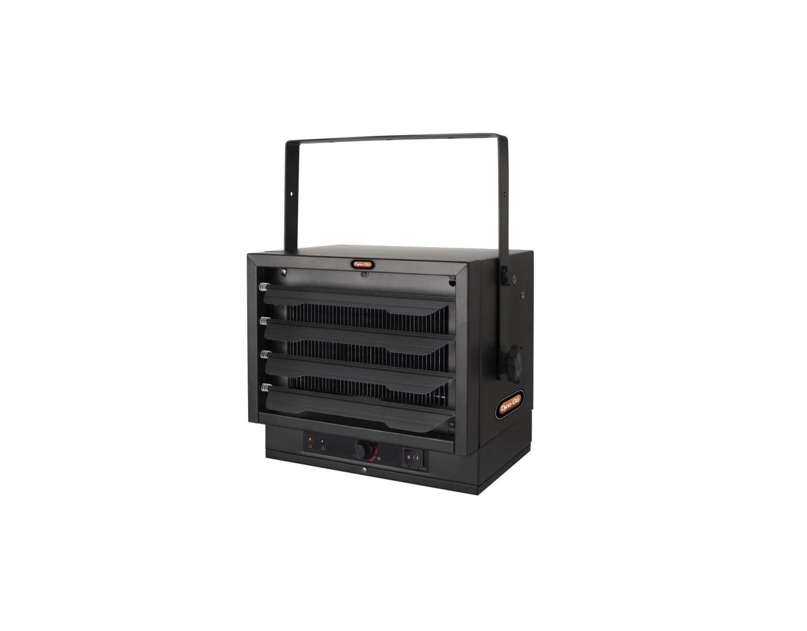
THERMO SPHERE Garage Heater with Remote Control Instruction Manual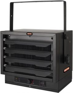 MODEL: HA24-50EB
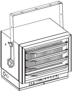 Figure: 1PET OWNERS WARNING: The health of some small pets, including birds, are extremely sensitive to the fumes produced during the initial use of many appliances. These fumes are not harmful to humans but we recommend that you do not use your heater around birds and small pets during its initial use until the manufacturing anti-corrosion coatings burn off.
IMPORTANT INSTRUCTIONS
When using electrical appliances, basic precautions should always be followed to reduce the risk of fire, electric shock, and injury to persons, including the following:
- Read all instructions before installing or using this heater.
- This heater is hot when in use. To avoid burns, do not let bare skin touch hot surfaces.Keep combustible materials, such as furniture, pillows, bedding, papers, clothes and curtains at least 3 feet (0.9 m) from the front of the heater and keep them away from the sides and rear.
- Extreme caution is necessary when any heater is used by or near children or invalids, and whenever the heater is left operating and unattended.
- Always turn off the power when not in use.
- Do not operate any heater after it malfunctions, has been dropped or damaged in any manner. Disconnect power at service panel and have heater inspected by a reputable electrician before reusing.
- Do not use outdoors.
- This heater is not intended for use in bathrooms, laundry areas and similar indoor locations. Never locate heater where it may fall into a bathtub or other water container.
- To disconnect heater, turn controls to off, and turn off power to heater circuit at main electrical panel.
- Do not insert or allow any foreign objects to enter any ventilation or exhaust openings as this may cause an electric shock, fire, or damage to the heater.
- To prevent a possible fire, do not block air intakes or exhaust in any manner. Do not use on soft surfaces, like a bed, where openings may be blocked.
- A heater has hot and arcing or sparking parts inside. Do not use it in areas where gasoline, paint, or flammable liquids are used or stored.
- All wiring must be carried out by a certified electrician and comply with national and local electrical codes in the United States and Canada
- Use this heater only as described in this manual. Any other use not recommended by the manufacturer may cause fire, electric shock, or personal injury.
- This heater may include a visual alarm to warn that parts of the heater are getting excessively hot. If the alarm illuminates, immediately turn the heater off and inspect for any objects on or adjacent to the heater that may have blocked the airflow or otherwise cause high temperatures. DO NOT OPERATE THE HEATER WITH THE ALARM ILLUMINATING.
- This appliance is not intended for use by persons (including children) with reduced physical, sensory or mental capabilities, or lack of experience and knowledge, unless they have been given supervision or instruction concerning use of the appliance by a person responsible for their safety. Children should be supervised to ensure that they do not play with the appliance.
SAVE THESE INSTRUCTIONS
DESCRIPTION
Electric utility heaters are designed to meet a variety of heating requirements by switching a few wires located in the base of the unit. Features horizontal and vertical air flow, built in thermostat and overheating safety thermal cut-out.
SPECIFICATIONS
|
Model |
Rating | Voltage | AMPS |
BTU/hour |
|
HA24-50EB |
5000W | 240V | 20.9 |
17,065 |
|
HEATER RATING&VOLTAGE |
HEATER AMPS | FUSE SIZE |
MIN.WIRE SIZE 60°C COPPER |
| 20.9 | 30 |
#10 |
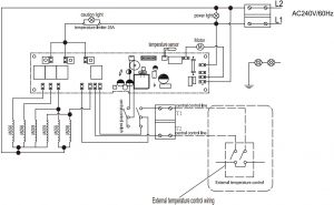
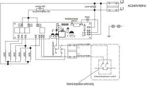 Circuit DiagramFigure: 2
Warning: This appliance must be grounded!Warning: The appliance must be connected to a current protection circuit or device with 30 Amp before being connected to power supply!
GENERAL SAFETY INFORMATION
Warning: This heater requires hardwire installation (no plug). The installation of this product must be carried out by a certified electrician in accordance with all applicable local and national electrical codes.
NOTE: Compatible with a 240V line voltage single pole wall thermostat. This thermostat must be installed by a certified electrician.
Warning: Read and understand all installation and operation instructions prior to operating this unit. Observe all safety instructions.
- Use only copper wires rated for at least 60ºC.
- Heater air flow must be directed parallel to or away from adjacent wall.
- Observe wall, floor and ceiling clearance requirements.
- All wiring must be done according to applicable national and local electrical codes in the United States and Canada. The heater must be grounded as a precaution against possible electrical shock. Heater circuit must be protected with proper fuses.
- The mounting and anchoring hardware must be capable of reliably supporting the weight of the heater and its mounting bracket.
- All electrical power must be disconnected and the main service box must be locked before inspecting cleaning or servicing the hater. This precaution must be followed to prevent serious electric shock.
- This heater is not suitable for use in hazardous locations as defined by the national fire protection association (NFPA) in the United States. This heater has hot and arcing sparking parts inside. Do not use it in areas where gasoline paint or flammable liquids are used or stored.
- This heater is not suitable for use in corrosive atmospheres such as marine greenhouses or chemical storage areas.
- This heater must be mounted at least 8 feet (2.44 m) above the floor.
Warning: Improper installation or failure to follow the procedures outlined in this instruction manual can result in serious electrical shock.
LOCATING HEATER
Install heater out of traffic areas, maintaining clearances stated in figure 3. The direction of air flow should not be restricted is by columns or machinery and the air flow should wipe exposed walls rather than blowing directly on them. When more than one heater is used in an area, the heaters should be arranged so that the air discharge of each heater supports the air flow of the others to provide best circulation of warm air as indicated in figure 4.
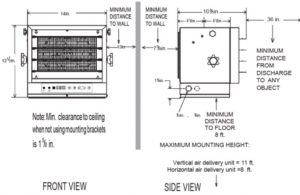 Figure: 3
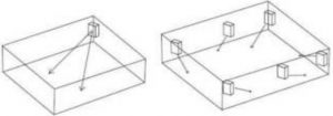 Figure: 4
INSTALLATION
Hardware neededYou will also need the following hardware, which can be purchased from your local hardware store or electrical supply store:
- Electric wire in the adequate gauge and length for your application.
- Proper size fuse or breaker for your heater’s amperage.
- Proper wire connectors for your application.
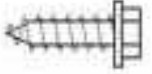
- Fasteners appropriate for your application that are strong enough to hold the unit.
MOUNTING THE HEATER ON THE CEILINGRefer to Figures 5a and 5b.
- Locate a wood stud in the wood ceiling joist. If you cannot locate a wood stud, you have to install a wood piece on the ceiling as this heater must be securely fastened.
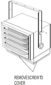
- Remove the mounting bracket from the heating unit by loosening bracket screws with a wrench and slipping the handle off over the screw heads.
- Place a washer on screws before inserting through the holes in the mounting bracket and screw them securely into a ceiling joist.
NOTE: If you want to swivel the heater either to the right or left adding a washer to both sides of the bracket is recommended. A longer lag bolt may be required to properly secure the unit. See Figure 5a.
 Figure 5a-single-Screw Mounting
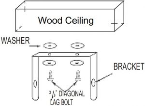 Figure 5b-Double-Screw Mounting
HANGING THE HEATER
- Lift the heater up and into the mounting bracket.
- Align the bracket screws with the keyhole slots in the mounting bracket.
- If the heater is to be tilted it must be positioned in the keyhole slots – see figure 6.
- Tighten the bracket screws with a wrench so the unit is securely suspended at horizontal or vertical level.
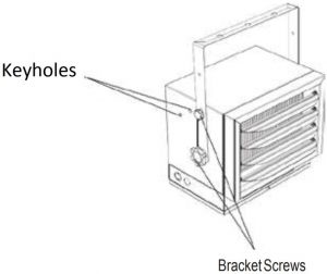
 USE BOTTOM KEYHOLE SLOTS IF HEATER IS TO BE TILTED DOWNFigure: 6
ADJUSTING AIR FLOW DIRECTION
- To turn the unit when it has been installed with a single lag bolt (as shown in figure 5a), simply turn the entire heater as needed(as shown in figure 7). The unit cannot be turned horizontally if it has been installed with 2 lag bolts.
- To tilt the unit vertically, loosen the bracket screws (see figure 6).
- Adjust louvers to the desired position.
NOTE: To prevent possible overheating, please maintain adequate clearance as shown in figure 3
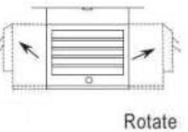 Figure: 7
NOTE: The louvers are designed so they cannot be completely closed. Do not attempt to defeat this feature; damage to the unit can result.
MULTIPLE VERTICAL ANGLES
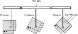 Figure: 8
MOUNTING THE HEATER ON THE WALL’S WOOD STUD ONLY
|
|
 |
 |
 |
 |
||
|
Tripod |
Support plate | M^*16 | M4*12 | ST10*30 | ST10*20 | Washer |
| 1 | 1 | 2 | 1 | 2 | 1 |
5 |
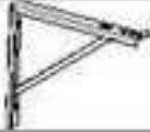
Refer to Figures 9A to 9E.
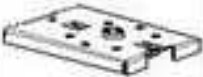
- Slide the support plate into the tripod; align both square holes and tighten with screws. (Figure 9A).
- Install the tripod on the wall with two screws. (Figure 9B).
- Attach the bracket on the heater, making sure it is securely fastened. (Figure 9C).
- Place the heater (with its bracket) on the support plate. The heater can be tilted at 3 different angles. Use two screws to secure the unit in the desired angle. (Figure 9D).
- Adjust the horizontal angle (Figure 9E).
Wall Hanging Installation (wood stud only)
- Slide the support plate into the tripod.
 Figure: 9A
 - Install the bracket on the wall with two screws (ST10*30*2)Figure: 9B
- Use the keyholes to lock different angles.Figure: 9C
- Attach the heater to the brackets with washer & screw (M10*20*1)Figure: 9D
- The heater can be fixed at 3 different angles. Use two screws (M6*16*2) to secure the unit in each angle.Figure: 9E
 Figure: 9A
 Figure: 9B
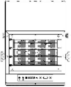 Figure: 9C
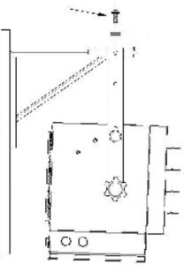 Figure: 9D
 Figure: 9E
NOTE: The louvers are designed so they cannot be completely closed. Do not attempt to defeat this feature; damage to the unit can result.
CONNECTING THE POWER
 External thermostat wiring diagram
NOTE: If you will use an external temperature control (external thermostat) with this heater, please follow instructions below:
NOTE: Turn off the power to the supply line for the heater before you select the build-in / external thermostat.
- Please find the rocker switch on the back of the heater as shown below and shift the switch to“ II”position to allow the heater to be controlled by an external thermostat.Figure: 10
- The external thermostat should comply with UL or ETL standard requirements.
- The lead wire of the external thermostat must have a minimum gauge of 16 AWG.
 Figure: 10
External thermostat installation
- Open the holes on the side.Figure: 11A
- Remove both screws.Figure: 11B
- Strip away the wire cover by 50mm From the external control box.Figure: 11C
- Twist the wire through the end.Figure: 11D
- Bend it into a circle.Figure: 11E
- Pass in the wires through the hole.Figure: 11F
- Connect the wires to the appliance and secure them.Figure: 11G
- Tighten the screws with a screwdriver.Figure: 11H
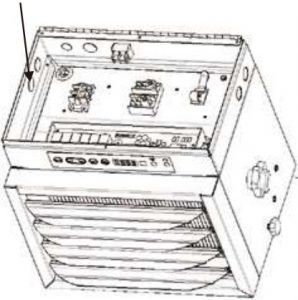 Figure: 11A
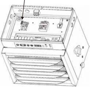 Figure: 11B
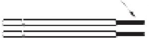 Figure: 11C
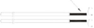 Figure: 11D
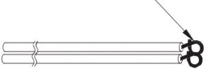 Figure: 11E
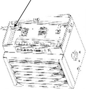 Figure: 11F
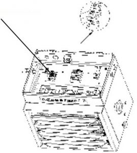 Figure: 11G
 Figure: 11H
CONNECTION OF POWER CABLES
- Remove the screw from the front of the unit to connect the power to the heater.
- Attach the cable connectors to the unit (See Figure 12) and slide the 8-gauge wire through the cable connector.
- Connect the wire to the power block located in the base of the heater – See Figure 13.
- Turn on the power at the main electrical panel.
NOTE: All wiring must be carried out by a certified electrician and must be in accordance to applicable national and local electrical codes. For certain applications, conduit may be required. Check local electrical codes. If you run the wiring in conduit and wish to be able to turn the heater be sure to purchase enough flexible conduits to allow the heater to be turned.
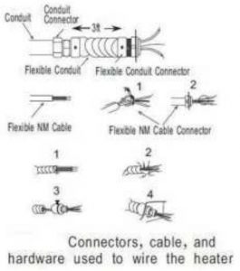 Figure: 12
 Figure: 13
OPERATING INSTRUCTIONS
Note: After setting an external thermostat to control the heater, the power selection & timer switch on the remote will be the only working function on the heater itself.
Control Panel
 Figure: 14
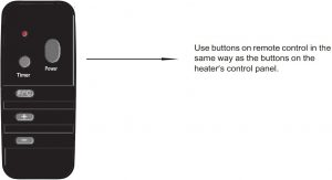 Figure: 15
Once the room temperature reaches the set point, the heater will automatically stop running. After each operation for 5 seconds, the LED displays the current Timer Power !Power Timer room temperature.
Instructions in Normal mode (temperature controlled by built-in thermostat)
Power buttonYou can use the power button as the Power switch.The power button is also used to change the heating output between low & high (L/H); the LED will display “L” or “H” accordinglyModel HA24-50EB: Low (L) →3000W; High (H) →5000W
Temperature selectionPress the “F/℃” button to change the temperature displayed between Fahrenheit and Celsius.Press the “+” or “-” button to set the desired temperature between 5 ℃ and 35 ℃.Hold down the “+” or “-” button to speed up the selection process.
Timer selec tionUse the “Timer” button to set the operating time of your heater, from 1 hour to 24 hours. With each press of the “Timer” button, the timer will increase by 1 hour on the LED screen.
TO PROTECT THE HEATING ELEMENTThe heater includes a fan delay function to prevent risk of overheating. When turning the heater off, the unit will close the heating element first and then the fan will continue working for 90 seconds to dissipate residual heat.
THERMAL CUT-OUTThe heater will automatically turn off when parts of it overheat. When this happens, the red indicator will turn on. The heater will turn ON again and the red indicator will turn off when the unit cools down back to normal levels, but the reason of the overheating must be determined and corrective action taken before further operation.
THE HEATER MUST STOP WORKING WHEN THE CAUTION INDICATOR IS GLOWING RED.
NOTE: When the thermal cut-out is activated, the caution indicator will turn red. In this case, immediately turn the heater OFF and inspect for any objects on or adjacent to the heater that may cause high temperatures. Let heater cool off completely before turning on again.
MAINTENANCE INSTRUCTIONS
- Before cleaning, make sure the power has been turned off at the circuit breaker panel and the heating element of the heater is completely cool.
- To maintain the appearance of the heater, it need only be wiped over occasionally with a dry duster. During the summer months, or at other times when the appliance is not in use and is completely cold, it can be cleaned by wiping it with a damp cloth. Do not let water drip inside the heater.
- Do not use abrasive clearing powders or furniture polish to clean this appliance. Do not use chemical or abrasive products, metallic scourers and similar items; they may deteriorate the surface.
- All servicing should be performed by qualified service personnel. Do not try to repair the heater yourself.
Technical Support: 1-866-206-0888Service email: [email protected]
[xyz-ips snippet=”download-snippet”]