
Infrared Thermometer Module User Manual V1.4
Features
- With housing, can be used directly, the sensor is factory calibrated, sensor resolution 24*32 dot matrix
- internal lithium battery 1000ma, rechargeable, mciro usb interface, interface voltage does not exceed 5v
- response frequency 8HZ, target temperature measurement range -40—–+300 degrees, use environment 0–50 degrees
- the emissivity can be adjusted from 0.01 to 1.00 range
- sensor probe field angle, default 35 degrees * 55 degrees MLX90640ESF-BAB probe
- screen 2.4 inch lcd 320 * 240 resolution, the screen shows the highest temperature, the lowest temperature, the center point temperature, display each coordinate point.
- Measurement accuracy ±2 degrees (test condition: environment 25 degrees, measurement target: boiling water 100 degrees, distance 30cm, coordinates Guangxi)
- with a screenshot function, you can pause the picture for analysis
- with the screen color corresponding to the temperature adjustment function, you can set the temperature to display different colors
- with USB data transmission interface, later upgradeable system, free update internal system, default system version 1.0
- Dimensions 80*50*26 (length, width, height, mm, excluding the raised part)
- With USB data transmission interface, the new firmware version automatically outputs data to the usb port by default. It can directly connect to the computer software to display images at the same time (computer software baud rate 115200), or use the corresponding serial port assistant to save image data.
Applications
- Human body temperature detection
- PCB component heating temperature detection
- Floor heating temperature detection
- Automotive parts temperature detection
- Electrical switch temperature detection
- Air conditioning, microwave oven testing
Instructions
- ε=0.95 current emissivity (object emissivity)
- T=31.9 master chip temperature
- battery power
- the lowest temperature
- the center of the field of view
- the highest temperature point
- the color shift value/Magnified multiple
- The temperature value corresponding to the leftmost end of the color bar
- the corresponding temperature value in the middle of the color bar
- the temperature value corresponding to the right end of the color bar
- the center of the field of view temperature
- the maximum temperature in the field of view
- the minimum temperature in the field of view
- infrared sensor temperature
- power on / off / menu / OK / stop button
- plus button
- minus button


Power On
Press the power button (15 in Figure 1) for more than 3 seconds to enter the boot screen.
Setting
When the camera is in working condition, press the menu button (15 in Figure 1) for more than half a second, less than 3 seconds, release the button to enter the setting interface.
Then press the plus/minus key to select the item to be set, red represents the currently selected item, press the OK key (15 in Figure 1) to enter the item.
Change the item value by pressing the plus/minus key, and then press OK. Press the key to return to the item selection, press the selection key to “EXIT”, and press the enter key to exit.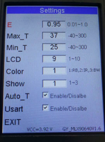
E:
Emissivity (0.01 to 1.00). Press the OK button to enter the item, press the plus/minus key to increase/decrease the value.
Max_T :
When Auto_T is not selected, the temperature value corresponding to the leftmost end of the color bar.Press the OK button to enter the item, press the plus/minus key to increase/decrease the value.
Min_T:
Auto_T The temperature value corresponding to the rightmost end of the color bar when it is not selected. Press OK button to enter the item, press the plus/minus key to increase/decrease the value.
When Auto_T is not selected
- If the maximum temperature in the field of view is greater than Mat_T, pin H will output a high level. When the maximum temperature is less than Mat_T 3 degrees Celsius, the pin outputs a low level.
- When the minimum temperature in the field of view is lower than Min_T, pin L will output a high level. When the minimum value is higher than Min_T 3 degrees Celsius, the pin outputs a low level.
LCD:
Screen brightness adjustment, ranging from 1-10. The larger the value, the higher the brightness.
Color:
Infrared thermal image matching scheme, the range of values is 1-3, 1 is Rainbow color, 2 is iron red, and 3 is black and white.
Figure 3 shows the image taken at a distance of about 20CM, followed by a rainbow—iron red—black and white.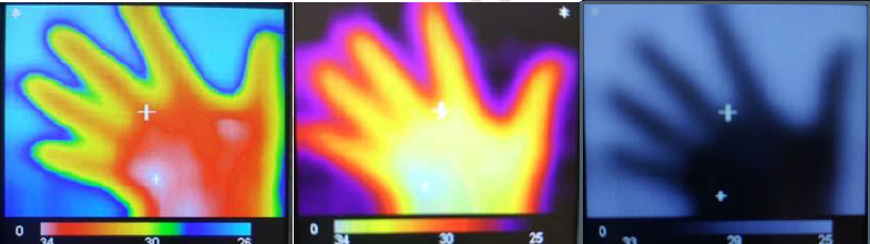
Show: Infrared thermal image temperature zone display level scheme, the value range is 1-3. The larger the value, the more obvious the temperature distinction. Figure 4 shows the values in the order of 1–2–3.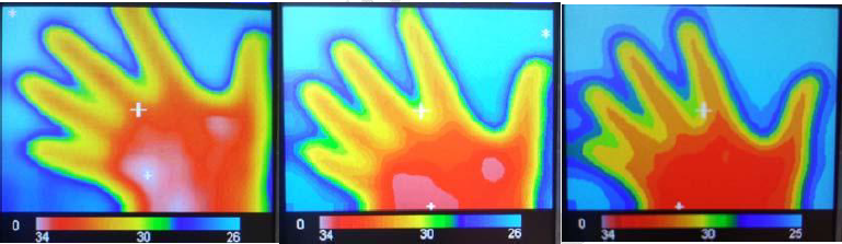
Auto_T:
In the selected state, the maximum temperature value in the field of view corresponds to the leftmost end of the color bar, and the minimum value corresponds to the far right end of the color bar. When unchecked, Max_T corresponds to the leftmost end of the color bar, and Min_T corresponds to the far right end of the color bar. Press the Enter key to enter the item, press the plus/minus key to select whether it is selected.
Usart:
When selected, the USB interface will be enabled to output 32*24 temperature values. Refer to the “GY_MPU90640 User Manual” for specific protocols.
EXIT:
Add/Subtract key After selecting this item, press the enter key to exit the setting interface.
VCC = 3.92V is the current battery voltage. GY_MLX90640V1.6 is the current firmware version.
Change the value of the color translation
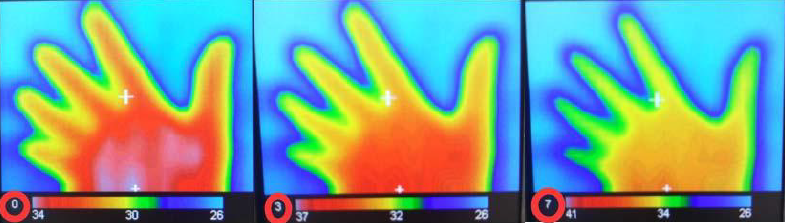
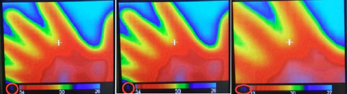
When the camera is in the working state, press the plus button, the color corresponding to the center point temperature of the field of view will approach the left end of the color bar. Press the minus button and it will approach the right end. For example, the translation value (red circled part) of Figure 5 is the effect diagram of 0–3–7. When you press the plus button, the offset value will be decremented by 1, and the minus key will be incremented by 1.
Pause function
When the camera is in operation, press the OK button and the display image will not be updated. The change color shift value function at this time can also be used. After pressing the confirmation button again, the image will continue to update.
Simple zoom function
When the camera is in working condition, press the confirmation button twice to enter the image zoom function. The image at this time is not updated. Press the confirmation button shortly to exit.Press the Add key once to enlarge the image by 0.5 times. The red circle in Figure 6 above shows the stepping value as 0–5–15, and the actual multiple value is 0–2.5–7.5.
Over temperature reminder

In Figure 7, the red circle position is the temperature of the main control chip. If the value exceeds 50 degrees, the color of the value will turn red. At this time, the camera should be turned off and the temperature should be lowered to normal value before use.
Battery display

In Figure 8, the left side shows the battery level in the charging state, and the right side shows the battery level in the power-on state (in 4 segments). When there are only 0 segments left, the battery icon is red. When the battery is too low, the camera will automatically shut down.Note: If the camera is not used for a long time, the battery should be stored at around 3.7V. The storage environment should be in a dry and dark place, and the temperature should not be too high.
Power Off

When long press the OK button for more than 3 seconds, the camera enters the shutdown interface, press the plus/minus button to select whether to shut down,press the Ok button to confirm.The camera will automatically save the parameters in the setup interface before shutting down.
Infrared Thermometer Module V1.4 User Manual – Infrared Thermometer Module V1.4 User Manual –
[xyz-ips snippet=”download-snippet”]