TIME GUARD TRT047N Wireless Digital Room Thermostat with Night Set-Back
General Information
These instructions should be read carefully and retained for further reference and maintenance.
Safety
- Before installation or maintenance, ensure the mains supply to the thermostat is switched off and the circuit supply fuses are removed or the circuit breaker turned off.
- It is recommended that a qualified electrician is consulted or used for the installation of this thermostat and install in accordance with the current IEE wiring and Building Regulations.
- Check that the total load on the circuit including when this thermostat is fitted does not exceed the rating of the circuit cable, fuse or circuit breaker.
- To clean use a clean dry cloth only. Do not use any liquid cleaners.
Technical Specifications
Receiver
|
|
|
|
|
3(1)A |
|
Single pole, voltage free changeover contacts |
|
3 wire |
|
Type 1.B control action |
|
Blue LED illuminated on setting for button surrounds |
|
Red LED |
|
Surface mount with wall plate |
|
|
|
90 x 95 x 30mm |
Transmitter
|
2x 1.5V AA |
|
0°C to +40°C |
|
10°C to 30°C |
|
+/- 0.5°C or 1.0°C set by DIP switch |
|
ON or OFF set by DIP switch |
|
3CYC = Gas, 6CYC = Oil, set by DIP switch |
|
5°C |
|
Lowers set temperature by 4°C for 1-9 hours |
|
868.3MHz |
|
Blue LED illuminated on setting for button surrounds and display |
|
Surface mount with wall plate |
|
|
|
90 x 95 x 30mm |
Transmitter Front View
Receiver Front View
Siting
Receiver
- The TRT047 Receiver should be mounted close to the items it will be controlling i.e. boiler, control valves and pump.
- It should be mounted in a position where its control buttons and indicator lights can be easily accessed.
Transmitter
- The TRT047N Transmitter must be sited where it will not be influenced by heat sources, for example above a radiator or a television or a refrigerator/freezer or in direct sunlight or subjected to draughts.
- The product requires air circulation, so do not position above or below shelving or other wall mounted obstacles.
- It should be mounted approximately 1.5 metres above floor level.
Installation
Receiver
- Ensure the mains supply is switched off and the circuit supply fuses are removed or the circuit breaker turned off. 5.2 Remove the wall plate from the receiver unit, by undoing the retaining screws, and pivoting the bottom of the unit outwards. The TRT047N receiver body can then be lifted off.
- Mark the position of the mounting holes on the wall using the wall plate as a template. Drill out the mounting holes taking care to avoid any joists, electrical cables or water/gas pipes that may be hidden beneath the surface. Insert the rawl plugs into the holes.
- Pass the 230V 50Hz mains supply and load cables through the opening of the wall plate. Allow sufficient excess cable to wire up the unit, but not too much to make it difficult to close the unit to the wall plate.
- Fix the wall plate to the wall using the correct mounting screws for the rawl plugs installed. The retaining screws which secure the unit to the wall plate should be at the bottom.
- Terminate the cables into the terminal block ensuring correct polarity is observed and that all bare conductors are sleeved (See section 6. Receiver Connection Diagram). Make sure that the curved washer grips the conductor.
- To reinstall the unit onto the wall plate, first ensure the wall plate retaining screws are loosened enough to clear the TRT047N receiver body, then engage the top of the TRT047N receiver onto the wall plate retaining tabs, and push firmly downwards and then upwards.There will be some resistance from the terminals.
- Once in place, secure with the retaining screws making sure not to over tighten.
Receiver Wall Plate
Transmitter
- Remove the wall plate from the transmitter unit, by undoing the retaining screws, and pivoting the bottom of the unit outwards. The TRT047N transmitter body can then be lifted off.
- Mark the position of the mounting holes on the wall using the wall plate as a template. Drill out the mounting holes taking care to avoid any joists, electrical cables or water/gas pipes that may be hidden beneath the surface. Insert the rawl plugs into the holes.
- Fix the wall plate to the wall using the correct mounting screws for the rawl plugs installed. The retaining screws which secure the unit to the wall plate should be at the bottom.
- To insert batteries into the unit, first lower hinged flip down cover and carefully lever the battery holder cover off. Insert the 2x AA batteries supplied into the battery holder maintaining the correct polarity, as shown in the base of the battery holder. Re-position the battery holder cover and click into place.
- To reinstall the unit onto the wall plate, first ensure the wall plate retaining screws are loosened enough to clear the TRT047N transmitter body, then engage the top of the TRT047N transmitter onto the wall plate retaining tabs, and push firmly downwards and then upwards.There will be some resistance from the terminals.
- Once in place, secure with the retaining screws making sure not to over tighten.
Transmitter Wall Plate
Connection Diagram
Connect the 230V 50Hz mains supply and load cables to the terminal block which are marked as follows;
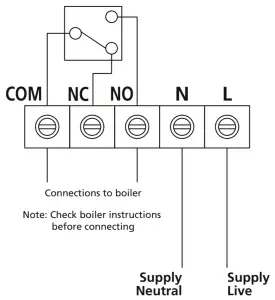
230V 50Hz Mains Supply
| 230V 50Hz Mains SupplyLive Supply (Brown or Red) to LNeutral Supply (Blue or Black) to NA ‘Loop Terminal’ is provided should a 3 core cable be used |
| Load (Boiler)Switch Live (Brown or Red) to NO |
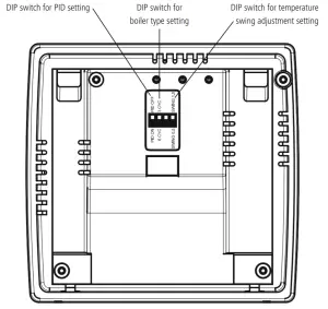
Transmitter DIP Switch Settings
- The temperature swing can be adjusted between 0.5°C and 1.0°C by selecting the desired DIP switch position found on the rear of the unit. We suggest using 0.5°C position unless the boiler turns ON and OFF too rapidly. Press the reset button after changing.
- The PID `Proportional-Integral-Derivative’ can also be selected ON or OFF using the DIP switches on the rear of the unit. We suggest setting this to the ON position. As the room temperature approaches the set temperature, the thermostat will intermittently turn the heating ON and OFF, to help prevent temperature over-shoot. Press the reset button after changing.
- The boiler type can be set to either 3CYC (Gas) or 6CYC (Oil), using the DIP switches on the rear of the unit. Press the reset button after changing.
TRT047N Rear of Transmitter
Pairing the Devices
- Make sure you have selected the desired DIP switch settings located on the back of the transmitter.
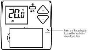
- Press the reset button of on the front of the transmitter, and connect the power to the receiver.

- Both the Learn/Manual light, and the Red output light on the receiver will illuminate for approximately 3 seconds, then go out.
- Press and hold the Learn button on the front of the receiver for 10 seconds until the blue Learn/Manual light starts flashing, the button surrounds will illuminate.
- On the transmitter, press and hold both the + and Frost/Night Set-back buttons at the same time until the flashing blue Learn/Manual light goes off. This should take approximately 3 seconds.
- The transmitter and receiver are now paired.
Operation
- The default set temperature is 22°C.
Adjusting Set Temperature
- Use the +/- setting buttons to change the set temperature.
- The set temperature will flash while the change is being made.
- The set temperature change will be made in 0.5 degree increments, and the +/- button surround and display light will illuminate upon setting.
- The set temperature and illumination will time out 5 seconds after the last button press, saving your settings, and the display will revert to show the current room temperature.
- When the room temperature is below the set temperature, the heating symbol will appear on the display to indicate output.
Frost Protection Mode
- Press the Frost/Night set-back button on the transmitter and hold for 3 seconds, the button surround and display light will illuminate.
- The frost symbol will appear and continuously flash on the screen. The set temperature will change to 5°C. The button surround, and display illumination will time out after 5 seconds.
- To disable the frost protection mode, press and hold the Frost/Night set-back button for 3 seconds. The frost symbol will disappear.
Night Set Back Mode
- The night set back reduces the set temperature by 4°C for a set amount of hours. This can be set between 1 and 9 hours.
- Press the Frost/Night set-back button once on the transmitter to activate, the button surround and display light will illuminate.
- The display will show 1 hour flashing.
- Use the +/- buttons to set the desired hours, the button surround will illuminate.
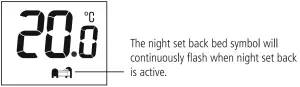
- When the correct number of hours is selected, the display will time out 3 seconds after the last button is pressed. The display will then alternate every 2.5 seconds between the number of hours of night set back remaining, and the current room temperature. The Night set back bed symbol will flash continuously whilst active.
- Press the frost/night set back button once again to cancel.

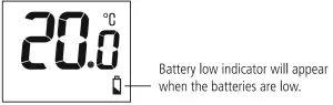
Battery Low Indicator
- When the batteries are low, the battery low indicator comes on.
3 Year Guarantee
In the unlikely event of this product becoming faulty due to defective material or manufacture within 3 years of the date of purchase, please return it to your supplier in the first year with proof of purchase and it will be replaced free of charge. For the second and third years or any difficulty in the first year telephone the helpline on 020 8450 0515.
Note: A proof of purchase is required in all cases. For all eligible replacements (where agreed by Timeguard) the customer is responsible for all shipping/postage charges outside of the UK. All shipping costs are to be paid in advance before a replacement is sent out.
 report this ad
If you experience problems, do not immediately return the unit to the store.Telephone the Timeguard Customer Helpline;
HELPLINE020 8450 0515or email [email protected]Qualified Customer Support Co-ordinators will be on-line to assist in resolving your query.A theben Group Company
For a product brochure please contact:Timeguard Limited.Victory Park, 400 Edgware Road,London NW2 6ND Sales Office: 020 8452 1112 or email [email protected]www.timeguard.com
References
[xyz-ips snippet=”download-snippet”]