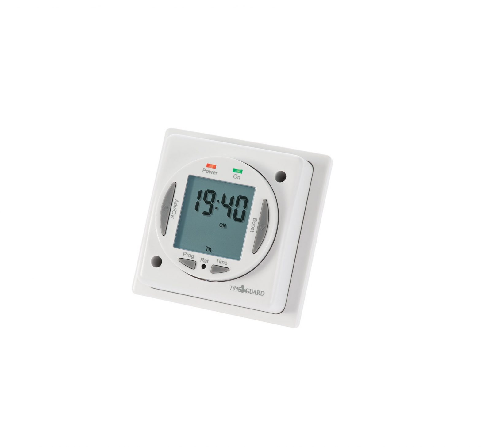
Timeguard 7 Day Digital Time Switch
General Information
These instructions should be read carefully and retained for further reference and maintenance.
Safety
- Before installation or maintenance, ensure the mains supply to the time switch is switched off and the circuit supply fuses are removed or the circuit breaker turned off.
- It is recommended that a qualified electrician is consulted or used for the installation of this time switch and install in accordance with the current IEE wiring and Building Regulations.
- Check that the total load on the circuit including when this time switch is fitted does not exceed the rating of the circuit cable, fuse or circuit breaker.
Technical Specifications
- 230V AC 50 Hz
- Switch Rating:16A Resistive (3.68kW) Immersion Heaters 2400W incandescent and halogen lighting 750W fluorescent lighting 100W Compact fluorescent & LED lighting
The LED switching capabilities of this product can be increased to 200W by the addition of the Timeguard ZV900 Automatic switch load controller – sold separately.
- Switch Type: 16A relay
- Voltage free contact: NTT04 only
- Contact Type: Normally Open
- Minimum Depth of Wall Box: 32mm
- Manual Override: Permanent ON or OFF
- Power Status LED Indicator: Red
- Output LED Indicator: Green
- 7 Day Time Period (7 Day, 5 + 2 Days or Individual Day) – 4 ON/OFF switching programmes per day
- Operating Temperature: 0°C to +40°C
- CE Approved
Note: Not suitable for use with Discharge Lighting.

Installation
- Ensure the mains supply is switched off and the circuit supply fuses are removed or the circuit breaker turned off.
- Remove the two bezel fixing screws, and remove bezel from timer module and wall plate.
- Ease the module forward without disconnecting, so you have access to the wall plate and loosen the screws on the terminal block for both supply and load cables.
- Ensuring that the free terminals on the wall plate are at the top, terminate the 230V 50Hz supply and load cables to the terminal block ensuring correct polarity is observed and that all bare conductors are sleeved. Please note the connections are marked on the rear side of the wall plate (see section 5. Connection Diagram).
- Fit the wall mounting screws through the wall plate and into the wall box threaded holes, and tighten until the wall plate is firmly fastened.
- Re-position the module back into place ensuring the time indicator is on the bottom right hand side, and the locating holes on the timer are set correctly on the pegs on the back plate.
- Re-fit the bezel over the timer module, and secure to the wall plate with the two fixing screws previously removed.
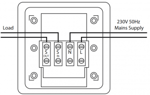
Connection Diagram
- The terminals are marked as follows on the rear of the wall plate;
NTT03 – 230V Mains Voltage Switching
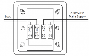
| 230V 50Hz Mains SupplyLive(Brown or Red) to LNeutral (Blue or Black) to N |
| LoadSwitch Live (Brown or Red) to SLNeutral (Blue or Black) to N OUT |
Note: this device needs to be left to charge for a minimum of 15 minutes once powered up, before it will operate
NTT04 – 230V Mains Voltage Switching
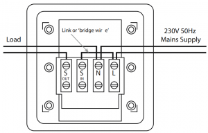
| 230V 50Hz Mains SupplyLive (Brown or Red) to LFit a ‘Link’ or ‘Bridge’ between L & S INNeutral (Blue or Black) to N |
| LoadSwitch Live (Brown or Red) to S OUTNeutral (Blue or Black) to N |
Note: this device needs to be left to charge for a minimum of 15 minutes once powered up, before it will operate.
NTT04 Only – Voltage Free Switching e.g. 24V lighting circuit
| 230V 50Hz Mains SupplyLive (Brown or Red) to LNeutral (Blue or Black) to N |
| LoadLive Input (for voltage free output) S INSwitch Live output (to low voltage appliance) to S OUT |
Note: this device needs to be left to charge for a minimum of 15 minutes once powered up, before it will operate.
Battery
- The time switch has a factory fitted rechargeable battery to give clock operation and programme memory back up during loss of mains supply.
- Before programming for the first time, connect the unit to the mains for at least 15 minutes prior to pressing the Rst button and programming the unit.
- If the display is not visible or very faint, charge for 4 hours prior to pressing Rst and programming.
- Approximately 720 hour battery reserve.
Reset
The time switch must be reset before programming for the first time, or after subsequent discharge for more than 5 days, and following a 4 hour period of charging.
- Press the Rst button once using a pointed object e.g. a pencil or a paper clip.
- The display will show all characters/digits and then will clear to show the following; ASCO = Automatic Summer/ Winter Change Over.

- Use the Adv/Ovr button to change between ON and OFF for the automatic summer time adjustment and proceed to section 8.

Setting the clock
- Press and hold the Time button for 3 seconds, the word Hold will show on the screen.
- After 3 seconds release the Time button and the screen will show the year;Use the Adv/Ovr to increase (or the Boost buttons to decrease) the value and set to the correct year.
- Press the Time button once to save the year, and the screen with show the month;
- Use the Adv/Ovr or boost button to set the correct month.
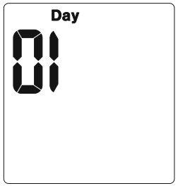
- Press the Time button once to save the month, and the screen will show the day;
- Press the Time button once to save the day, and the screen will show the time – hour first;Note: The hour is in 24 hour format.
- Use the Adv/Ovr or boost button to adjust to the correct hour.
- Press the Time button once to save the hour, and the minutes can be adjusted.
- Use the Adv/Ovr or boost button to adjust to the correct minutes.
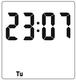
- Press the Time button once to exit the Time/date entry mode.
- The display should now show the correct time/day of the week, for example;
 Use the Adv/Ovr to increase (or the Boost buttons to decrease) the value and set to the correct year.
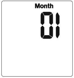

Modifying the date and time of day
Normally the only change required will be to the time of day minutes, in which case;
- Press and hold the Time button for 3 seconds, the word Hold will show on the screen.
- After 3 seconds release the Time button and the screen will show the year;
- Press the Time button repeatedly until the minutes are shown.
- Use Adv/Ovr or Boost to change the minutes to the correct value.
- Press the Time button once to return to operating mode.Note: Other changes can be made the same way, but the Time button must be pressed to return to operating mode after any changes. There is no automatic exit from Time/date entry mode.
Programming ON/OFF times
The NTT03/04 has 4 independent On/Off periods available for programming each day. There is a choice of programming options, including 7 days the same (24 hours), 5 + 2 days (where the weekdays are the same, and the two weekend days are the same), and 7 individual days
- Press and hold the Prg button for 3 seconds, the word Hold will show on the screen.
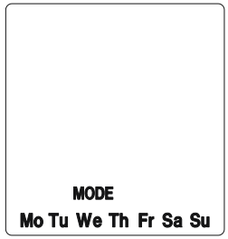
- After 3 seconds release the Prg button and the MODE screen will be displayed;
- Use the Adv/Ovr or Boost to change the day grouping mode. This will step through the following options; 24hour – Mo Tu We Th Fr Sa Su 5 day – Mo TuWe Th Fr (followed automatically in programming by 2 day – Sa Su) Individual day – Mo (followed automatically in programming by each of the other days of the week).
- Once the desired day grouping is selected, press Prg button once to set and move onto programming the ON/OFF times.
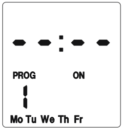
- The display will show Prog 1, with dashes for the hours and minutes;Note: the example shown is for 5 day + 2 day programming.
- Use Adv/Ovr or Boost button to set the hour for the first ON period.
- Press the Prg button once to set and move you to the minutes.
- Use Adv/Ovr or Boost button to set the minutes for the first ON period.
- Press the Prg button once to set and move you to the Programme 1 OFF time.
- Use Adv/Ovr or Boost button to set the hour for the first OFF period.
- Press the Prg button once to set and move you to the minutes.
- Use Adv/Ovr or Boost button to set the minutes for the first OFF period.
- Press the Prg button to scroll through Programme 2 ON, Programme 2 OFF, Programme 3 ON, Programme 3 OFF, Programme 4 ON and programme 4 OFF, adding in times as required. Note: If further times are not required, just eave the dashes in place and scroll past the rest of the programs using the Prg button.
- After Programme 4 has been entered, then next day grouping will follow e.g. In this example the day grouping will change to 2 day – Sa Su Programme 1 ON.
- Programme the ON/OFF times as before.
- After the last OFF time for programme 4 has been set, press the Prg button once to exit the programme mode.Note: At any stage in programming, if the Prg button is pressed and held for 3 seconds, the timer will return to normal operating mode.
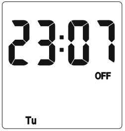
- The display will now show the correct time and day as per this example;
- At this stage the output ON/OFF indicator (as in the above image) may not reflect the current programme status accurately.
- If the time switch should be OFF now, leave as it is.Note: The time switch will automatically turn ON at your desired ON time, and will resume the next programme as normal.
- If the time switch should be ON now, press the Adv button once and set it too ON ADVANCE;Note: The time switch will now automatically turn OFF at your desired OFF time, and will resume the next programme as normal.
- In the same way as for individual programmes, days or groups of days can be omitted either by leaving dashes in all the locations for ON/OFF times for that day or group of days. Alternatively, leaving the programme entry mode before filling in all the ON/OFF times will leave the remaining times blank.

Note: The only way to re-enter a blank times (or dashes) is to reset the unit.
Programming across midnight
- Enter the required programme 1 ON time.
- Set the programme 1 OFF time to 00:00 (i.e. midnight).
- Set the programme 2 ON time to 00:00 as well.
- Enter the required programme 2 OFF time for the next day
Modifying or adding programmes
- Press and hold the Prg button for 3 seconds, the word Hold will show on the screen.
- After 3 seconds release the Prg button and the MODE screen will be displayed. Note: This will automatically display the mode in which it was last programmed.For instance, if it was programmed in 5 + 2, then it will show Mo Tu We Th Fr.
- Either – Accept this by pressing the Prg button once, and review the programmed times for this mode by pressing Prg to move through the times.
- Or – Press the Adv/Over or Boost button to change the mode, and then press the Prg button to review the times.Note: If you wish to change the mode at this stage, doing so will result in programmes being lost and they will need to be re-entered.
- Review times and adjust as necessary as described at the start of section 9.
In normal operating mode the Adv/Ovr button advances the programme to the next time change.
- If the output is currently OFF, it will change the output to ON ADVANCE, until the next programmed OFF time.
- If the output is currently ON, it will change the output to OFF ADVANCE, until the next programmed ON time.
- A second push of the Adv/Ovr button selects a permanent ON mode, ON OVERRIDE, where the output is ON irrespective of the programming.
- A third push of the Adv/Ovr button selects a permanent OFF mode, OFF OVERRIDE, where the output is OFF irrespective of the programming.
- A fourth push of the Adv/Ovr button returns the unit to normal operating mode, where the output will conform to the programming.
- One press of the boost button will provide 1 hour of boost, after which the output will turn OFF.
- Two presses of the boost button will provide 2 hours of boost, after which the output will turn OFF.
- A third press of the boost button will cancel any boost period and return you to normal operating mode.
3 Year Guarantee
In the unlikely event of this product becoming faulty due to defective material or manufacture within 3 years of the date of purchase, please return it to your supplier in the first year with proof of purchase and it will be replaced free of charge. For the second and third years or any difficulty in the first year telephone the helpline on 020 8450 0515.
Note: A proof of purchase is required in all cases. For all eligible replacements (where agreed by Timeguard) the customer is responsible for all shipping/postage charges outside of the UK. All shipping costs are to be paid in advance before a replacement is sent out.

If you experience problems, do not immediately return the unit to the store. Telephone the Timeguard Customer Helpline;
HELPLINE020 8450 0515or email[email protected]Qualified Customer Support Co-ordinators will be on-line to assist in resolving your query
For a product brochure please contact:
Timeguard Limited.Victory Park, 400 Edgware Road,London NW2 6NDSales Office: 020 8452 1112or email [email protected]
References
[xyz-ips snippet=”download-snippet”]