![]()
 MODEL NO: TGBD2, TGBD4
1. General Information
These instructions should be read carefully and retained for further reference and maintenance.
2. Safety
• Before installation or maintenance, ensure the mains supply to the boost timer is switched off and the circuit supply fuses are removed or the circuit breaker turned off. It is recommended that a qualified electrician is consulted or used for the installation of this time switch and installed in accordance with the current IEE wiring and Building Regulations.• Check that the total load on the circuit including when this boost timer is fitted does not exceed the rating of the circuit cable, fuse or circuit breaker.
3. Technical Specifications 230V AC 50 Hz . Class II
- 230VAC 50 Hz
- Class II
- Unfused
- Switch Rating; 13A Resistive (3kW) 1000W filament or halogen lighting 500W Fluorescent lighting 200W LED lighting
- Contract Type: Normally Open
- Minimum Depth of Wall Box: 25mm
- Boost Times: l5minutes – 2 hours (TGBD2) 15minutes – 4 hours (TGBD4)
- Power Status: LED indicator
- Operating Temperature: 0°C to +45°C
- CE Compliant
- Dimensions (H x W x D): 85 x 85mm x 35mm
- Front projection: 24mmNote: Not suitable for use with Discharge Lighting
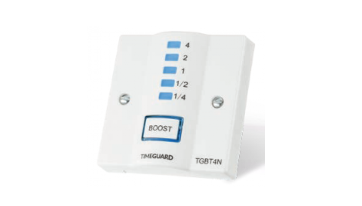
Also available in the Boost timer range:
- TGBT6 2 hour plug-in boost timer.
- FBT4N 4 hours fused spur boost timer.
Example
4. Installation
Note: The installation of this electronic time delay switch should be protected by a suitable fuse or breaker of up to 13A rating.
- Ensure the mains supply is switched off and the circuit supply fuses are removed or the circuit breaker turned off.
- Connect the incoming 230V 50Hz supply and outgoing load cables to the relevant terminals ensuring correct polarity is observed and that all bare conductors are sleeved (see section 5. Connection Diagram).
- A front cable exit cut-out is provided with a pre-installed removable cover.
- If the front exiting cable cut-out is required:
1. Undo the 2 fixing screws and remove the blanking plate (you can discard the blanking plate at this stage but keep the 2 fixing screws).2. Remove the cable grip from the accessory pack.3. Using the 2 fixing screws previously removed from the blanking plate, secure the load cable to the unit. Select ON/OFF for the boost button backlight:ON – Always ONOFF- Always OFF
- Finally secure the unit to the backbox with the fixing screws provided, forming the cables during installation to avoid any entrapment and cable damage.
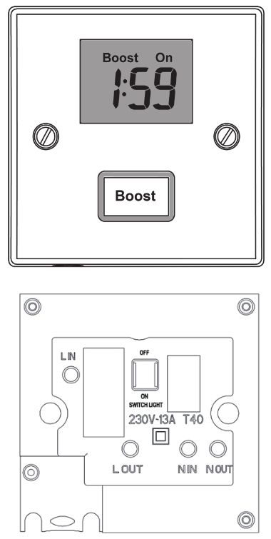
Connecting Diagram
The terminal are marked as follows on the rear of the boost timer:
Example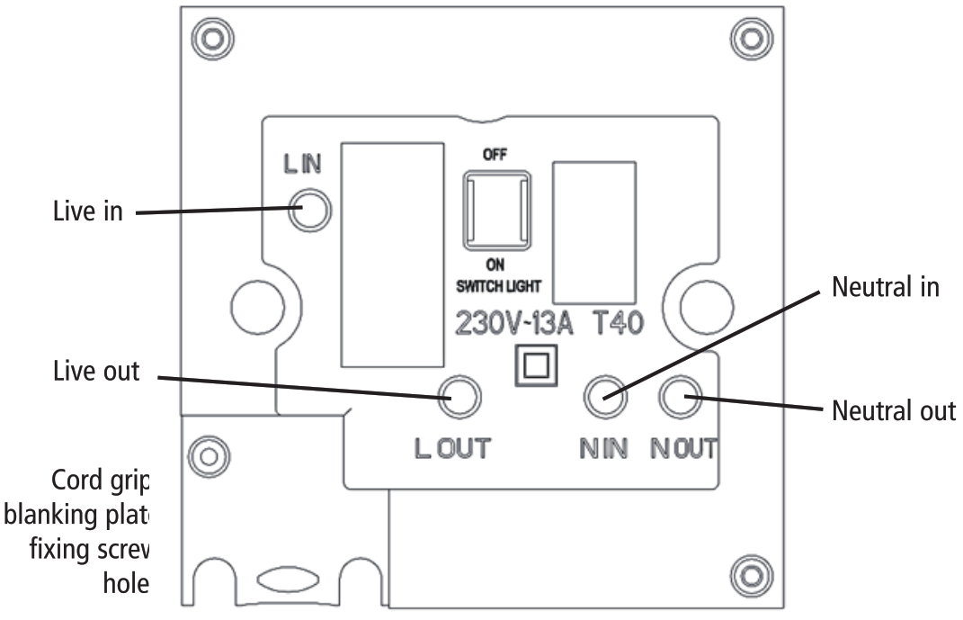
| Main SupplyLive (Brown of Red) to L INNeutral (Blue Black) to NIN |
| LoadSwitch (Brown of Red) to LOUTNeutral (Blue Black) to OUT |
Operation
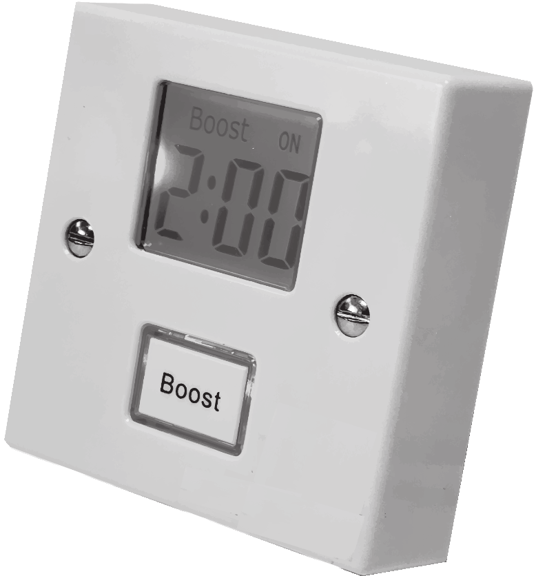
- The required boost time is selected by pressing the button marked boost, repeatedly. The digital display will show the selected boost period in 15-minute increments.
- The digital display (above the Boost button) will light up and display the time selected:The first push gives 15 minutes boostThe second push gives 30 minutes boostThe third push gives 45 minutes boostThe fourth push gives 1-hour boostSubsequent pushes of the boost button will increase the time in 15-minute increments.Pressing and holding the boost button will increase the time in 1-hour increments.Once the maximum rated time of the timer is reached (2 or 4 hours) pushing the boost button again will revert the timer to OFF with the display showing “Boost OFF”.
- Once the desired boost time is showing in the display and after approximately 4 seconds of the boost button not being pressed again the connected device to the timer will be switched ON and the display will change to show “Boost ON” and the time remaining.
Note: The TGBD2 (2 Hour Version) gives 15-minute increments and the TGBD4 (4 Hour Version) gives 30-minute increments
Stopping or Increasing Boost
- Once the boost timer is ON and has started to count down it can be stopped at any time by pressing the boost button once. The connected device will be switched OFF immediately.
- The Boost period cannot be increased once the count downtime has started and the display is showing “Boost ON”
- The boost button backlight can be changed to – Permanently ON or Permanently OFF. (Please see section 4)
- The Display backlight will only illuminate once the boost button has been pressed and during the boost ON period.
3 Year Guarantee
In the unlikely event of this product becoming faulty due to defective material or manufacture within 3 years of the date of purchase, please return it to the vendor where the product was purchased from.
Note: A proof of purchase is required in all cases. For all eligible replacements (where agreed by Timeguard) the customer is responsible for all shipping/postage charges outside of the UK. All shipping costs are to be paid in advance before a replacement is sent out.

Note: If you have any concerns that the intended application of this product does not meet your requirements, please contact Timeguard directly prior to installation.
If you experience problems, do not immediately return the unit to the store. Email the Timeguard Customer Helpline:HELPLINEemail: [email protected] or telephone 0208 450 0515Customer Support Co-ordinators will be online to assist in resolving your query.![]() A been Group CompanyFor a product brochure please contact:Timeguard Limited.Victory Park, 400 Edgware Road, London NW2 6ND Sales Office: 020 8452 1112 or email [email protected]www.timeguard.com67.058.479 (Issue 1)
A been Group CompanyFor a product brochure please contact:Timeguard Limited.Victory Park, 400 Edgware Road, London NW2 6ND Sales Office: 020 8452 1112 or email [email protected]www.timeguard.com67.058.479 (Issue 1)
[xyz-ips snippet=”download-snippet”]