Timken Ball Bearing Housed Unit
Installation Guide
UC 200 AND UC 300 SERIES
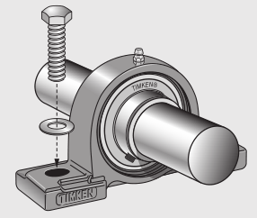
SET SCREW STYLE UNITS
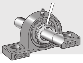
Set screw style units are mounted on the shaft with the help of two set screws in the inner ring located at 120 degrees to each other. The set screw locking mechanism provides ease in mounting and is suitable for applications where the shaft rotation is bidirectional.
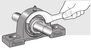
Installation procedures for set screw style units are shown below.
- Ensure that the shaft is clean, free from burrs, straight and of proper diameter. The bearing should not be mounted on a worn section of the shaft. Using shafts with hardness greater than HRC 45 will reduce effectiveness of locking devices. See table 2 for suggested shaft tolerances.
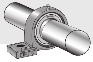
- Install the supplied grease fitting into the threaded lubrication hole on the housing. Align the bearing in its housing and slide the unit into position on the shaft.

- Bolt the housing tightly to its mounting supports using an appropriately sized fastener and suggested bolt torque (table 4). Flat washers should be used when installing any kind of housed unit. Washers should be properly sized to bolt diameter.
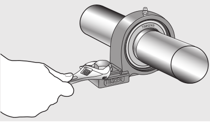
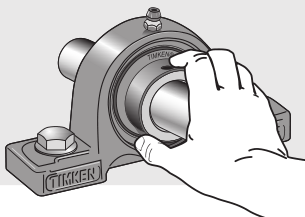
- Lock the bearing to the shaft by tightening each inner ring set screw incrementally to suggested torque levels (see table 3).


UK SERIES
ADAPTER STYLE UNITS
Adapter style units have a tapered bore bearing mounted to the shaft with adapter sleeve assembly, comprised of an adapter sleeve, locknut and lockwasher. This design offers the best shaft concentricity and highest capacity while having the ability to accommodate undersized shafting. These units are most suitable where they are exposed to excessive vibration and impact.
Installation procedures for adapter style units are shown below.
- Ensure that the shaft is clean, free from burrs, straight and of proper diameter. The bearing should not be mounted on a worn section of the shaft. See table 5 for suggested shaft tolerances.
- Slide the adapter sleeve into position on the shaft. If the sleeve is too tight, expand the slot by using a screwdriver as required.
- Slide the bearing unit over the adapter sleeve and loosely install the housed unit to its mounting supports using an appropriately sized fastener. Flat washers should be used when installing any kind of housed unit. Washers should be properly sized to bolt diameter.
- Assemble the lockwasher on the sleeve and thread the locknut onto the adapter sleeve leaving approximately 6.35 mm (1/4 in.) between the lockwasher and the inner ring of the bearing.
- Use a large screwdriver or pry bar to lever the sleeve into position until there is no relative movement between the shaft, adapter sleeve and the bearing’s inner ring.
- Rotate the locknut until hand-tight. Use a spanner wrench to tighten the locknut to the suggested torque (see table 6).
- Bend a tang on the lockwasher into a slot on the locknut to prevent the locknut from loosening.
- Rotate the shaft by hand while tightening the mounting bolts to make sure the shaft rotates freely. Tighten the housed unit mounting bolts to the recommended bolt tightening torque given in table 4.
UEL SERIES
ECCENTRIC LOCKING COLLAR UNITS
The self-locking collar eliminates the need for locknuts, lockwashers, shoulders, sleeves and adapters. For many agricultural and industrial applications, self-locking collars are the easiest housed units to install. The locking collar has a recessed cam made eccentric to the collar bore. When assembled on the shaft, the locking collar engages or mates with the eccentric cam end of a bearing’s inner ring. This assembly grips the shaft tightly with a positive binding action that increases with use. No adjustments of any kind are necessary. The collar set screw provides supplementary locking.
Installation procedures for eccentric locking collar style units are shown below.
- Ensure that the shaft is clean, free from burrs, straight and of proper diameter. The bearing should not be mounted on a worn section of the shaft. Using shafts with hardness greater than HRC 45 will reduce effectiveness of locking devices. See table 2 for suggested shaft tolerances.
- Install the supplied grease fitting into the threaded lubrication hole on the housing. Align the bearing in its housing and slide the unit into position on the shaft.
- Bolt the housing tightly to its mounting supports using an appropriately sized fastener and suggested bolt torque (see table 4). Flat washers should be used when installing any kind of housed unit. Washers should be properly sized to bolt diameter.
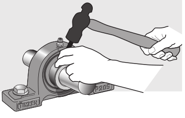
- Place the eccentric locking collar on the shaft with its cam adjacent to the cam on the end of the bearing inner ring. The eccentric collar’s recessed cam will engage the corresponding cam on the bearing inner ring. Turn the collar in the direction of shaft rotation.
- Using a light weight hammer and a drift pin inserted in the blind hole, tap lightly in the direction of shaft rotation to positively engage the collar. The insert is now locked to the shaft.
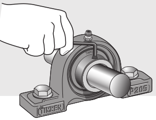
- Tighten the set screw to suggested torque level (see table 3).
RELUBRICATION
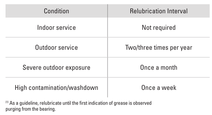
Timken ball bearing housed units are prelubricated. However, periodic relubrication is advisable in some applications for which these units aredesigned. Consult your equipment manufacturer’s operating manual for the specific relubrication cycle. General guidelines are found in table 1 below.
TABLE 1. GENERAL RELUBRICATION SUGGESTIONS FOR GREASED BEARINGS (1)
TECHNICAL DATA
The following tables provide useful installation details related to shaft tolerance, recommended torque for set screws and mounting bolts and bearing internal clearances.
TABLE 2. SUGGESTED SHAFT TOLERANCE (1)
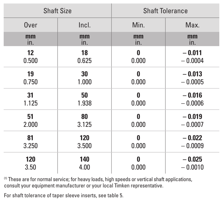
TABLE 3. SUGGESTED SET SCREW TIGHTENING TORQUE
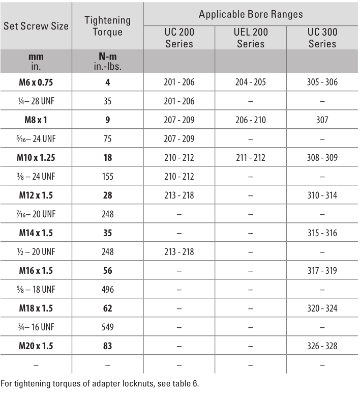
TABLE 4. SUGGESTED MOUNTING BOLT TORQUE

Since tapered bore bearings are fixed to the shaft with an adapter, a looser fit is allowable since the adapter sleeve provides excellent concentricity. This makes mounting of the bearing to the shaft much easier. Table 5 shows the dimensional tolerance of the shaft used with tapered bore bearings (with adapters).
TABLE 5. DIMENSIONAL TOLERANCE OF SHAFT USED FOR TAPERED BORE BEARINGS (WITH ADAPTERS)

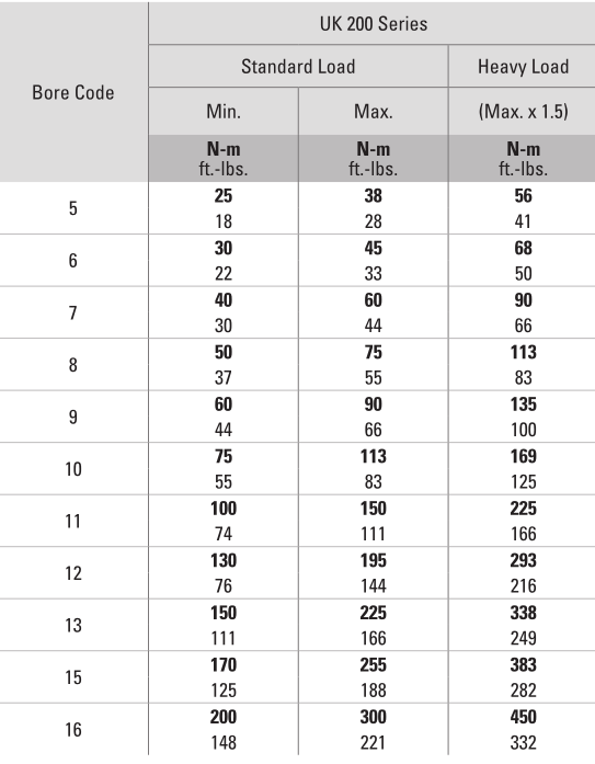
TABLE 6. TIGHTENING TORQUES OF ADAPTER LOCKNUTS (REFERENCE)
RADIAL INTERNAL CLEARANCE
In the manufacture of ball bearings, it is standard practice to assemble rings and rolling elements with a specified internal clearance. This characteristic is necessary to absorb the loss of clearance due to press fitting the bearing rings at mounting or due to expansion of bearings, shafts and housings. Internal clearance in an application is an important factor that has a significant influence on bearing performance as wellas characteristics of heat, noise and vibration.
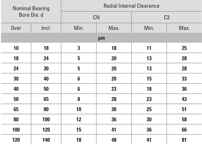
Table 7 shows the applicable internal clearance for different series bearings and Table 8 shows the available options for internal clearance.
TABLE 7. INTERNAL CLEARANCES – DIFFERENT SERIES
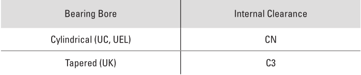
TABLE 8. INTERNAL CLEARANCE
Remarks
- Radial internal clearance given in the above table comply with JIS B 1558.
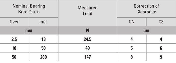
- Increase in the internal clearance caused due to the applied measured load is given in the Table 9 below. The correction is applicable to the maximum clearance.
TABLE 9. CORRECTION OF CLEARANCE

Proper maintenance and handling practices are critical. Always follow installation instructions and maintain proper lubrication.Overheated bearings can ignite explosive atmospheres. Special care must be taken to properly select, install, maintain and lubricate housed unit bearings that are used in or near atmospheres that may contain explosive levels of combustible gases or accumulations of dust such as grain, coal, or other combustible materials. Consult your equipment designer or supplier for installation and maintenance instructions.If hammer and bar are used for installation or removal of a part, use a mild steel bar (e.g., 1010 or 1020 grade). Mils steel bars are less likely to cause release of high speed fragments from the hammer or bar or the part being installed or removed.
NOTE:Do not use excessive force when mounting or dismounting the unit.Follow all tolerance, fit and torque recommendations.Always follow the Original Equipment Manufacturer’s installation and maintenance guidelines.Ensure proper alignment.Never weld housed units.Do not heat components with an open flame.Do not operate at bearing temperatures above 250° F (121° C).
For additional Timken product warnings, visit www.timken.com/warnings.

The Timken team applies their know-how to improve the reliability and performance of machinery in diverse markets worldwide. The company designs, makes and markets high-performance mechanical components, including bearings, belts, brakes, clutches, chain, couplings, gears and related mechanical power transmission products and services.
05-18 Form No. T00612 | Timken ® is a registered trademark of The Timken Company. | © 2018 The Timken Company
Timken Ball Bearing Housed Unit Installation Guide – Timken Ball Bearing Housed Unit Installation Guide –