
Tire Linc® Tire Pressure & Temperature Monitoring System 2.0 Installation and Owner’s Manual
(For Aftermarket Applications)
| Tire Linc Aftermarket Kit | |
| Part # | Description |
| 2020106863 | Tire Linc® 4-stem sensor kit |
| 2020106299 | Tire Linc® stem sensor 2-pack; for spare sensors or triple axle trailer |
Introduction
Tire Linc® is a tire pressure and temperature monitoring system (TPMS). The TPMS issues an alert via the OneControl® app when a trailer’s tire(s) pressure or temperature falls out of the programmable range.
Key System Components
- Sensors – Stem mount, 188 psi maximum pressure reading, -58 to 401 °F (-50 to 205 °C) temperature measurement range.
- Repeater – Receives sensor data, communicates with Phone App via Bluetooth Low Energy (BLE).
- Repeater Dock – Provides power to repeater, which “docks” to this base.
- OneControl App – Displays real-time tire pressures, temperatures and visual alerts for faults.
NOTE: Images used in this document are for reference only when assembling, installing and/or operating this product. Actual appearance of provided and/or purchased parts and assemblies may differ.
Parts List Additional information about this product can be obtained from lci1.com/support or by using the myLCI app.
Replacement kits can be ordered from https://store.lci1.com/ or by using the myLCI app.
The myLCI app is available for free on iTunes® for iPhone® and iPad® and also on Google Play™ for Android™ users.
iTunes®, iPhone®, and iPad® are registered trademarks of Apple Inc.
Google Play™ and Android™ are trademarks of Google Inc.
Safety
Read and fully understand all instructions before installing or operating this product. Adhere to all safety labels. This manual provides general instructions. Many variables can change the circumstances of the instructions, e.g., the degree of difficulty, operation and ability of the individual performing the instructions. This manual cannot begin to plot out instructions for every possibility, but provides the general instructions, as necessary, for effectively interfacing with the device, product or system. Failure to correctly follow the provided instructions may result in death, serious personal injury, severe product and/or property damage, including voiding of the LCI limited warranty.
![]()
THE “WARNING” SYMBOL ABOVE IS A SIGN AN INSTALLATION PROCEDURE HAS A SAFETY RISK AND MAY CAUSE DEATH OR SERIOUS PERSONAL INJURY, SEVERE PRODUCT AND/OR PROPERTY DAMAGE IF NOT PERFORMED SAFELY AND WITHIN PARAMETERS SET FORTH IN THIS MANUAL.
![]()
THE “CAUTION” SYMBOL ABOVE IS A SIGN AN INSTALLATION PROCEDURE HAS A SAFETY RISK INVOLVED AND MAY CAUSE PERSONAL INJURY, PRODUCT AND/OR PROPERTY DAMAGE IF NOT PERFORMED SAFELY AND WITHIN THE PARAMETERS SET FORTH IN THIS MANUAL.
Parts List
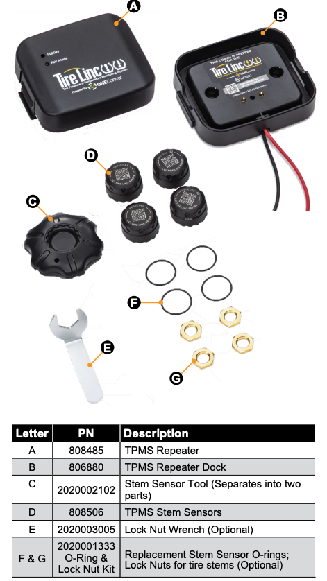
NOTE: Part numbers are shown for identification purposes only. Not all parts are available for individual sale. All parts with a link to the Lippert Store can be purchased.
Resources Required
- OneControl® app
- Cordless or electric drill or screw gun
- Appropriate drive bits
- #8 x 3/4″ self-tapping pan head screws
- Wire strippers
- Appropriate electrical connectors
Installation of Repeater Dock
Install Tire Linc on a non-prepped trailer as follows:
NOTE: Non-prepped trailers do not have a repeater dock installed; prepped trailers do. If a repeater dock is installed, go to Installation and Setup section.
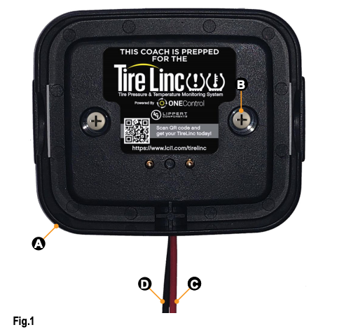
- Locate a mounting area inside the trailer that allows connection of the Tire Linc repeater dock (Fig.1A) to the unit’s power source without creating a strain on the completed connection.
- Vertically orient the repeater dock and secure it to the wall with two #8 x 3/4″ self-tapping pan head screws (Fig.1B) (not supplied).
- Make sure power to the trailer is off, then connect the repeater dock’s red power wire (Fig.1C) and black ground wire (Fig.1D) to system power and ground as follows:
A. If necessary, use wire strippers to expose enough bare wire to make a good connection.B. Use appropriate electrical connectors to create good connections.C. Make sure there is a 15A maximum circuit protection placed in-line between the power supply and the repeater dock.
Installation and Setup
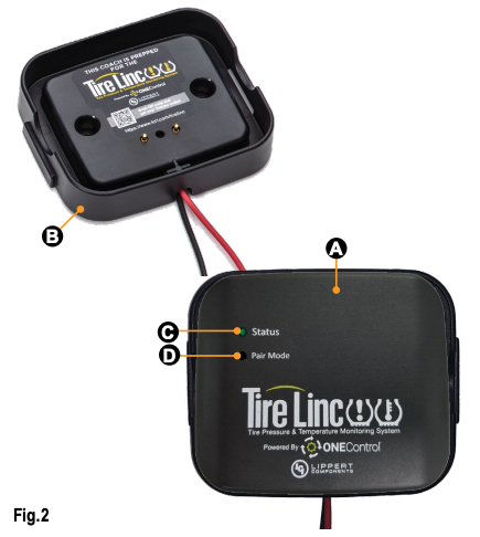
Snap the repeater (Fig.2A) into the dock (Fig.2B).
NOTE: The dock is keyed and the repeater can only be snapped in one way.
- The repeater will power on, lighting up the Status LED (Fig.2C), blinking to indicate the repeater has power.

- If the Status LED does not light up, check the in-line fuse to the dock to ensure the dock has power.
- Use the small tip of a tool or tip of a pen and push and hold for five seconds, then release the Pair Mode button (Fig.2D). The Status LED will turn on solid for one second, then blink twice to indicate it’s in pairing mode.
Connect One Control App to Repeater
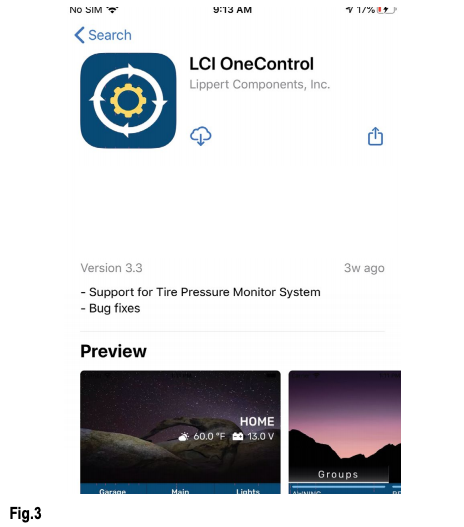
- Download the LCI OneControl app (Fig.3) for either an iOS or Android smart phone.
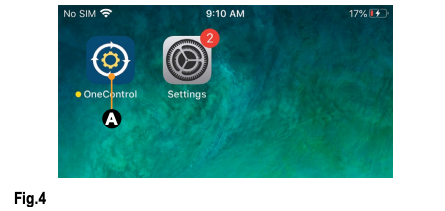
- After the LCI OneControl app has been downloaded, tap the OneControl icon (Fig.4A) to launch the app.
- Follow the app’s installation prompts to configure the OneControl app.NOTE: Optionally, press the Pair Mode button (Fig.2D) on the Repeater and look for TireLinc in the app’s listing.
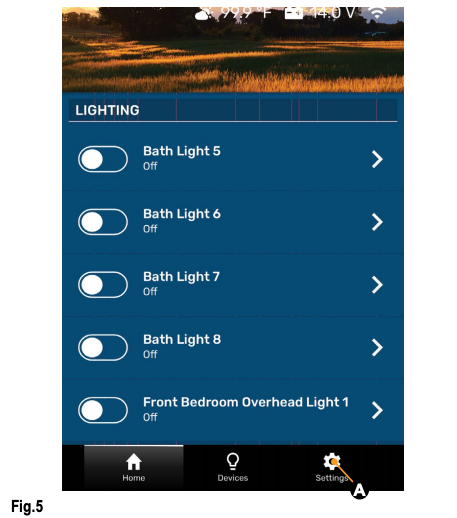
- Press the Settings button (Fig.5A) at the bottom of the OneControl page.
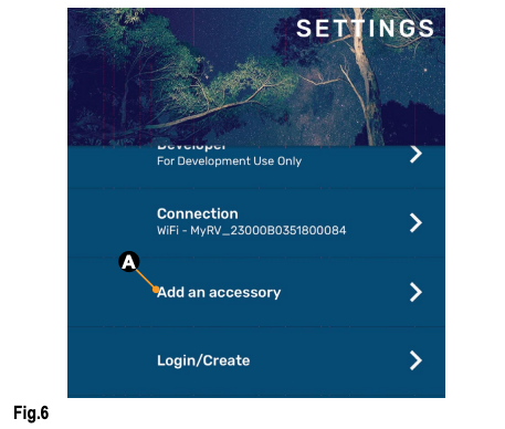
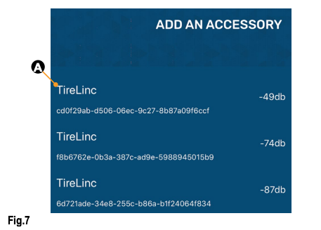
- Select the “Add an accessory” button (Fig.6A).
- When the “scan for devices” window appears, look for TireLinc in the list. Select the one with the strongest RSSI value (Fig.7A). For instance:A. -60 is greater than -70; select -60 because it is the stronger number.B. 20 is greater than 10; select 20 because it is the stronger number.
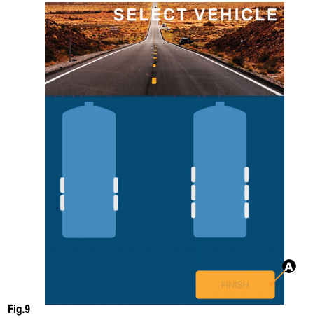
- Select a vehicle class (Fig.8) and press continue.
- Select a vehicle and press finish (Fig.9A).

Stem Sensor Pairing Sequence
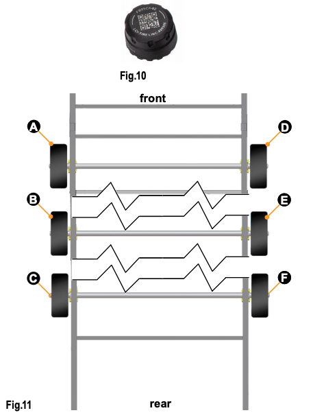
The pairing sequence for Stem Sensors (Fig.10) is as follows:
- SINGLE AXLE: Stem Sensors for a single axle trailer MUST be paired in the following order: Left front (Fig.11A), right front (Fig.11D).
- DOUBLE AXLE: Stem Sensors for a double axle trailer MUST be paired in the following order: Left front (Fig.11A), left rear (Fig.11B), right front (Fig.11D), right rear (Fig.11E).
- TRIPLE AXLE: Stem Sensors for a triple axle trailer MUST be paired in the following order: Left front (Fig.11A), left middle (Fig.11B), left rear (Fig.11C), right front (Fig.11D), right middle (Fig.11E), right rear (Fig.11F).
Use Smart Phone to Pair Sensors to Repeater
NOTE: If a wrong trailer type is chosen or there is a new trailer configuration, see Troubleshooting section for factory reset.
The OneControl app on the smart phone will indicate in specific order which tire the stem sensor cap should be installed: Front Left, Rear Left, Front Right, Rear Right, etc.
- Have Stem Sensors (Fig.10) available to install on the tire stems and remove any existing stem caps from the tires.NOTE: If using the lock nuts as a theft deterrent, add the lock nuts to the tire stems but make sure there is room to add the sensors. Lock nuts will be tightened later. The lock nuts are optional and are not required to be installed.
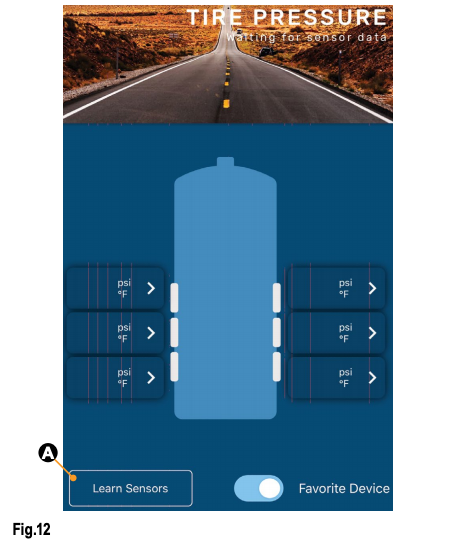
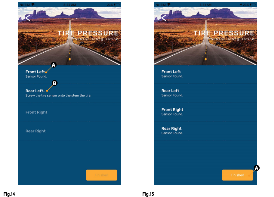
- Pair stem sensors to the repeater as follows:A. Select the Learn Sensors button (Fig.12A) in the TIRE PRESSURE app screen. The app will display a list of tires with instructions to screw the first stem sensor onto the Front Left tire stem (Fig.13).B. Install a stem sensor onto the tire stem in the proper sequence (Fig.11) and wait for the smart phone to indicate the sensor was found (Fig.14A).NOTE: It may take up to 30 seconds for the sensor to awake and be found.C. If the sensor is not seen within 30 seconds, unscrew the sensor from the tire stem, wait approximately 10 seconds and then reinstall the sensor. Do not proceed to install any other sensors until the app shows the sensor found.D. After the sensor has been found, the app will indicate the next tire sensor to be paired (Fig.14B).
- Repeat steps 2B, 2C and 2D until all sensors are learned (Fig.15).
- Press the Finished button (Fig.15A) to exit TIRE PRESSURE Sensor Configuration mode.Pressing Finished exits configuration mode and redisplays the TIRE PRESSURE screen. DO NOT press the LEARN SENSORS button again. Doing so resets Tire Linc into configuration mode, which requires uninstalling the Stem Sensors.NOTE: To exit learn mode, press the back arrow and the sensors will not be forgotten.NOTE: When learning has been completed, the low and high pressure limits of the tires are estimated at +/- 20% of the last received sensor data. Make sure sensors are not removed during the learning process or the pressure limit values will be incorrectly estimated. Pressure and temperature limits can be set through the app after learning has been completed.NOTE: If installing the optional lock nut as a theft deterrent, loosen stem sensor slightly and hand tighten lock nut against the sensor. Using wrench provided in kit, hold lock nut in position and hand tighten stem sensor against lock nut.
 B. Install a stem sensor onto the tire stem in the proper sequence (Fig.11) and wait for the smart phone to indicate the sensor was found (Fig.14A).NOTE: It may take up to 30 seconds for the sensor to awake and be found.C. If the sensor is not seen within 30 seconds, unscrew the sensor from the tire stem, wait approximately 10 seconds and then reinstall the sensor. Do not proceed to install any other sensors until the app shows the sensor found.D. After the sensor has been found, the app will indicate the next tire sensor to be paired (Fig.14B).
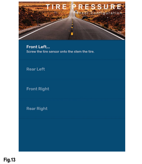
Operation
When Stem Sensors are under pressure, data is transmitted to the repeater, when tires are:
- moving/rotating, every one minute;
- not moving/not rotating, every 15 minutes.
- If using the LCI OneControl app (Fig.4), for either an iOS or Android smart phone (Fig.5), do as follows:A. Tap the OneControl icon (Fig.5A) to launch the app.B. The app will automatically detect the Tire Linc system.NOTE: If necessary, follow the online prompts to set up Tire Linc within the OneControl app.
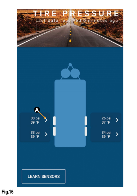
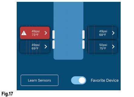
- The smart phone will connect to the repeater and the app will display a trailer image with tire pressures and temperatures (Fig.16).NOTE: Figure 16 shows tire pressures and temperatures within the specification ranges for the left front tire while figure 17 shows the tire is outside specification ranges.
- With the OneControl app running, real-time tire event notifications will be sent to the smart phone.
- Tap the notification to be taken to the TPMS screen in OneControl to visually see which tire(s) is/are experiencing an event.
- Tap the readout button (Fig.16A) of a tire to launch its properties window (Fig.18). Within the selected tire’s properties window, various tire and sensor specifications can be observed and altered.A. Last data received — posts the date and time the app last received tire monitoring system information.B. Pressure — posts the currently sensed pressure of the selected tire.C. Temperature — posts the currently sensed temperature of the selected tire.D. Battery Level — posts the current battery voltage of the sensor’s battery.E. Low/High Pressure Threshold — posts the currently programmed low and high pressure limit for the selected tire.F. High Temperature Threshold — posts the currently programmed high temperature limit for the selected tire.G. Maximum Temperature Change Limit — posts the currently programmed maximum +/- temperature change limit for the selected tire.
 F. High Temperature Threshold — posts the currently programmed high temperature limit for the selected tire.G. Maximum Temperature Change Limit — posts the currently programmed maximum +/- temperature change limit for the selected tire.
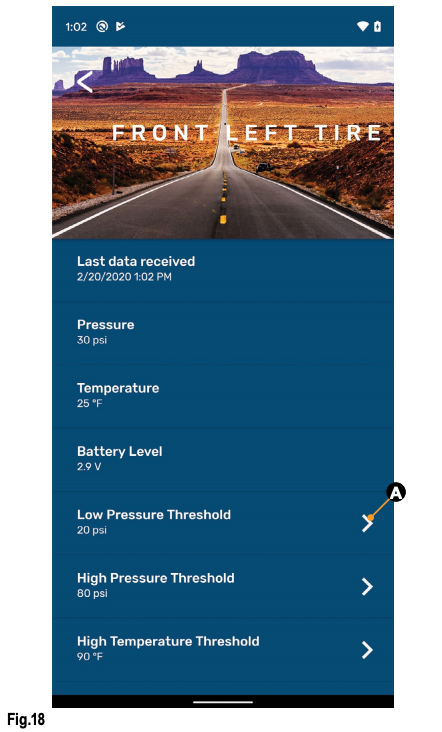
![]()
UNDER OR OVER PRESSURIZED TIRES CAN CAUSE UNFORESEEN, DETRIMENTAL EFFECTS ON TIRES AND UNIT, INCLUDING UNDESIRABLE TREAD WEAR. TIRES SHOULD ALWAYS BE PRESSURIZED TO WITHIN THE MANUFACTURER’S RECOMMENDATIONS.
Tire Limits Example
Programmable tire limits have a “next” arrow (>) (Fig.16A) that, when tapped, opens that feature’s scrollable window of available settings. Scroll through the limits window to find the desired setting, select it, then tap the “back” arrow (<) (Fig.18) located above the tire’s name at the top of the window’s heading.
The following example illustrates the interaction between the various tire settings and how the resulting information is relayed by the monitoring system for display in the app.
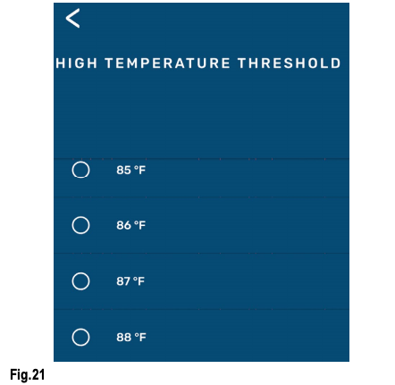
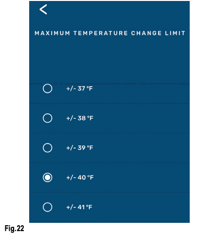
- Select a tire by tapping its information button (Fig.16A) to launch its settings window — FRONT LEFT TIRE.A. In this example, the reported current tire Pressure is listed as “30 psi” (Fig.18).B. Compare the tire’s low/high pressure range (20 – 80 psi) against the reported tire pressure (30 psi). Always make sure tire pressures are within recommended limits.C. If the High Pressure Threshold requires adjusting, tap the next arrow to launch its settings window (Fig.19). Scroll through the window until the current setting is found, then scroll to a desired, higher limit and select it.D. If the Low Pressure Threshold requires adjusting, tap the next arrow to launch its settings window (Fig.20). Scroll through the window until the current setting is found, then scroll to a desired limit and select it.E. The High Temperature Threshold (Fig.21) and the Maximum Temperature Change Limit (Fig.22) can also be adjusted.


Troubleshooting
Remove Stem Sensor to Change Battery
Removal of the Stem Sensor battery can be completed with the included Stem Sensor tool. The Stem Sensor tool, which is taken apart to utilize, is comprised of two pieces molded to match the tops and bottoms of the Stem Sensors. Slightly rotate the pieces opposite of each other and then carefully pry them apart to separate. One piece is used on top of the Stem Sensor and one piece of the tool is used on the bottom.
If the Stem Sensor batteries fail, replace them as follows:
- Remove Stem Sensor from tire stem.NOTE: If using the optional lock nuts as a theft deterrent, use the supplied wrench to hold the lock nut while unscrewing the sensor from the tire stem.
- Using the Stem Sensor tool with a piece on top and a piece on the bottom of the Stem Sensor, unscrew the top cap of the Stem Sensor to expose the battery.
- Replace battery with CR1632 3V lithium coin battery.NOTE: Replacement batteries are not included.
- Replace supplied Stem Sensor O-ring when replacing battery.
No Power
If system is not working, check the in-line fuse to the dock to ensure the dock has power.
Learn Sensors Procedure Resets System
DO NOT press the LEARN SENSORS button. Doing so resets Tire Linc into configuration mode, which requires uninstalling the stem sensors.
Factory Reset
In the event a wrong trailer type is chosen or if there is a new trailer configuration, the settings can be reset.
- Press and hold the pair button on the repeater for approximately 10 seconds.
- Continue holding the button until there is one long red blink followed by four red blinks.
- Release button.
Notes
Manual information may be distributed as a complete document only, unless Lippert Components provides explicit consent to distribute individual parts.
All manual information is subject to change without notice. Revised editions will be available for free download at lci1.com. Manual information is considered factual until made obsolete by a revised version.
Please recycle all obsolete materials and contact Lippert Components with concerns or questions.
References
[xyz-ips snippet=”download-snippet”]