![]()
![]() OWNER’S MANUAL
OWNER’S MANUAL
MPN(s): UPHDPWRv2-24HDPWR, UPHDPWRv2-36HDPWR, BENCH,UPHDPWRv2-24HDPWR-INBENCH, UPHDPWRv2-36HDPWR-BENCH
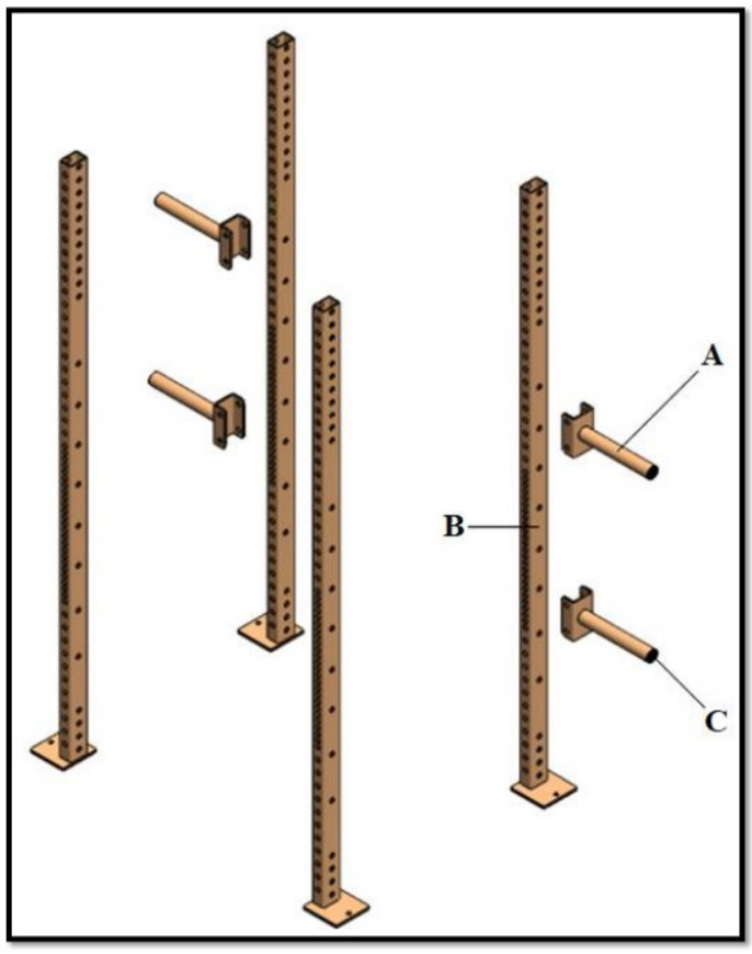
UPHDPWRV2 PARTS DIAGRAM
| KEY | DESCRIPTION | QTY |
| (A) | WEIGHT HOLDER | x4 |
| (B) | UPRIGHT | x4 |
| (C) | TUBE END CAP | x4 |
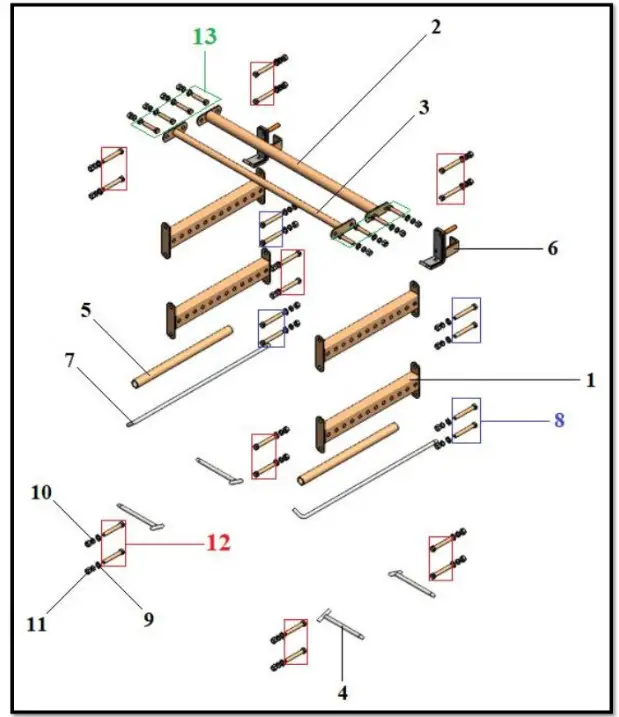
24HDPWR/36HDPWR PARTS DIAGRAM
| KEY | DESCRIPTION | QTY |
| (1) | SIDE BRACE | x4 |
| (2) | 2″ PULL-UP BAR | xl |
| (3) | 1.25″ PULL-UP BAR | xl |
| (4) | BAND PEG | x4 |
| (5) | SPOTTING BAR SLEEVE | x2 |
| (6) | HDJ-HOOK | x2 |
| (7) | SPOTTING BAR | x2 |
| (8) | HEX BOLT M16x120 | x8 |
| (9) | FLAT WASHER M16 | x32 |
| (10) | SPRING WASHER M16 | x32 |
| (11) | HEX NUT M16 | x32 |
| (12) | HEX BOLT M16x110 | x16 |
| (13) | HEX BOLT M16x80 | x8 |
UPHDPWRV2-24HDPWR/36HDPWR ASSEMBLY INSTRUCTIONS
STEP 1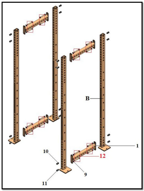 STEP 2Use hardware that is identified below for both sides of a part’s installation.
 —– THIS CONCLUDES THE ASSEMBLY OF THE UPHDPWRV2-24HDPWR/36HDPWR. —–
IN THE BENCH PARTS DIAGRAM
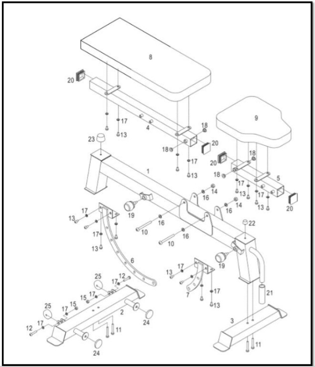
| KEY # | DESCRIPTION | QTY |
| (1) | FRAME | xl |
| (2) | REAR STABILIZER | xl |
| (3) | FRONT STABILIZER | x1 |
| (4) | BACKREST FRAME | xl |
| (5) | SEAT FRAME | xl |
| (6) | BACKREST PIVOT BRACKET | xl |
| (7) | SEAT PIVOT BRACKET | xl |
| (8) | BACKREST | xl |
| (9) | SEAT | x1 |
| (10) | M10x100 BOLT | x2 |
| (11) | M8x60 BOLT | x4 |
| (12) | M8x40 BOLT | x2 |
| (13) | M8x15 BOLT | x16 |
| (14) | M10 NYLON LOCKNUT | a |
| (15) | M8 NYLON LOCKNUT | a |
| (16) | 6410 WASHER | x4 |
| (17) | M8 WASHER | x20 |
| (18) | INNER WASHER #10.5 | x4 |
| (19) | POP PIN | a |
| (20) | SQUARE INNER CAP | x4 |
| (21) | HANDLE | xl |
| (22) | RING | x2 |
| (23) | CUSHION | xl |
| (24) | ROUND DOME | a |
| (25) | WHEEL | x2 |
IN BENCH ASSEMBLY INSTRUCTIONS
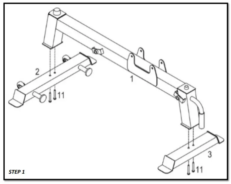
- SECURE THE FRAME (1) TO THE REAR STABILIZER (2) AND THE FRONT STABILIZER (3)a. Align the holes at the base of the FRAME (1) to those drilled through the REAR STABILIZER (2).b. Insert an M8x60 BOLT (11) through one hole and partially tighten the M8x60 BOLT (11).c. Insert an M8x60 BOLT (11) through the remaining hole and partially tighten the M8x60 BOLT (11).d. When both M8x60 BOLTS (11) are in place and partially tightened, tighten the M8x60 BOLTS (11) until the FRAME (1) is securely attached to the REARSTABILIZER (2).e. Repeat the above order for attaching the FRAME (1) to the FRONT STABILIZER (3).

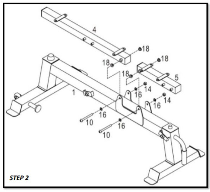
- ATTACH THE BACKREST FRAME (4) AND SEAT FRAME (5) TO THE FRAME (1):a. Align the topmost hole of the BACKREST FRAME (4), which is located within the bracket on the FRAME (1), with the hole through the bracket located closest to the REAR STABILIZER (2).b. Attach the BACKREST FRAME (4) to the FRAME (1) using M10x100 BOLT (10), M10 WASHER (16), M10 NYLON LOCKNUT (14), and INNER WASHER #10.5 (18). The order for assembly is as follows: M10x100 BOLT (10), M10 WASHER (16), FRAME (1), INNER WASHER #10.5 (18), BACKREST FRAME (4), INNER WASHER #10.5 (18), FRAME (1), M10 WASHER (16), and M10 NYLON LOCKNUT (14).c. Once each piece is in place, tighten down the M10 NYLON LOCKNUT (14).d. Align the bottommost hole of the SEAT FRAME (5), which is located within the bracket on the FRAME (1), with the hole through the bracket located closest to the FRONT STABILIZER (3).e. Repeat the above order for assembly.f. Once each piece is in place, tighten down the M10 NYLON LOCKNUT (14).
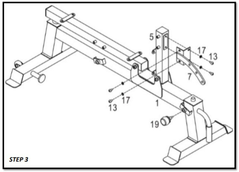
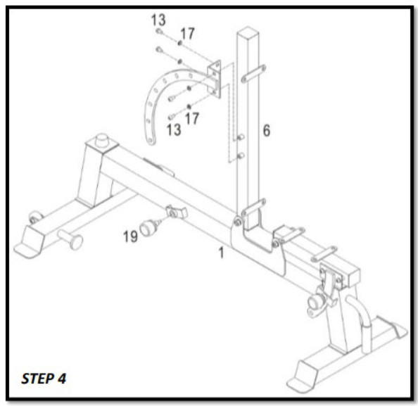
- ATTACH THE SEAT FRAME (5) TO THE SEAT PIVOT BRACKET (7) AND THE POP-PIN (19) TO THE FRAME (1):a. Align the holes of the SEAT PIVOT BRACKET (7) with those on the SEAT FRAME (5).b. Attach the SEAT PIVOT BRACKET (7) to the SEAT FRAME (5) using an M8x15 BOLT (13) and an M8 WASHER (17). The order for assembly is as follows: M8x15 BOLT (13), M8 WASHER (17), SEAT PIVOT BRACKET (7), and SEAT FRAME (5).c. Lightly tighten down the M8x15 BOLT (13) and repeat the process for the remaining SEAT PIVOT BRACKET (7) placement points.d. Tighten down each M8x15 BOLT (13) when all are in place.e. Insert the SEAT PIVOT BRACKET (7) into the bracket located on the side of the FRAME (1) and insert the POP PIN (19) through the bracket and the SEAT PIVOT BRACKET (7).f. Screw the POP PIN (19) into position. (This will lock the SEAT PIVOT BRACKET (7) in place and be how the height of the seat is adjusted.)
- ATTACH THE BACKREST FRAME (4) TO THE BACKREST PIVOT BRACKET (6) AND THE POP-PIN (19) TO THE FRAME (1):a. Align the holes of the BACKREST PIVOT BRACKET (6) with those on the BACKREST FRAME (4).b. Attach the BACKREST PIVOT BRACKET (6) to the BACKREST FRAME (4) using M8x15 BOLT (13) and M8 WASHER (17). The order for assembly is as follows: M8x15 BOLT (13), M8 WASHER (17), BACKREST PIVOT BRACKET (6), and BACKREST FRAME (4).c. Lightly tighten down the M8x15 BOLT (13) and repeat the process for the remaining BACKREST PIVOT BRACKET (6) placement points.d. Tighten down each M8x15 BOLT (13) when all are in place.e. Insert the BACKREST PIVOT BRACKET (6) into the bracket located on the side of the FRAME (1) and insert the POP PIN (19) through the bracket and the BACKREST PIVOT BRACKET (6).f. Screw the POP PIN (19) into position. (This will lock the BACKREST PIVOT BRACKET (6) in place and be how the height of the backrest is adjusted.)
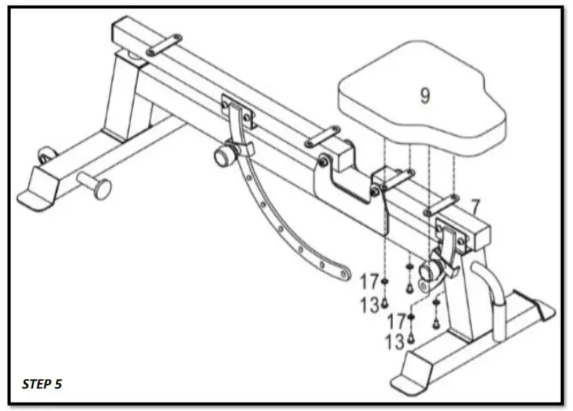
- SECURE THE SEAT (9) TO THE SEAT FRAME (5):a. Align the holes on the base of the SEAT (9) to the holes drilled in the brackets located on top of the SEAT FRAME (5).b. Secure the SEAT (9) to the SEAT FRAME (5) using an M8x15 BOLT (13) and an M8 WASHER (17). The order for assembly is as follows: M8x15 BOLT (13), M8 WASHER (17), SEAT FRAME (5), and then SEAT (9).c. Lightly tighten down the M8x15 BOLT (13) and repeat the above process for securing the remaining side of the SEAT (9).d. Once all pieces are in place, completely tighten down the M8x15 BOLTS (13). 9
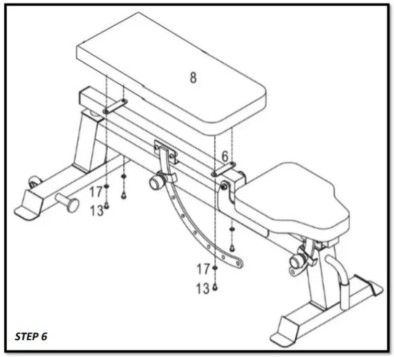
- SECURE THE BACKREST (8) TO THE BACKREST FRAME (4):a. Align the holes on the base of the BACKREST (8) to the holes drilled in the brackets located on top of the BACKREST FRAME (4).b. Secure the BACKREST (8) to the BACKREST FRAME (4) using an M8x15 BOLT (13) and an M8 WASHER (17). The order for assembly is as follows: M8x15 BOLT (13), M8 WASHER (17), BACKREST FRAME (4), and then BACKREST (8).c. Lightly tighten down the M8x15 BOLT (13) and repeat the above process for securing the remaining side of the BACKREST (8).d. Once all pieces are in place, completely tighten down the M8x15 BOLTS (13).
| This concludes the UPHDPWRv2Owner’s Manual.If applicable to your product, make sure to tightenall nut-and-bolt combinations before use.Enjoy! |
|
DISCLAIMER
This equipment must be used with care by capable and competent individuals under supervision, if necessary.
The use of any fitness equipment, including this one, involves the potential risk of injury. You accept and assume full responsibility for any and all injuries, damages (both economic and non-economic), and losses of any type, which may occur, and you fully and forever release and discharge Titan, its insurers, employees, officers, directors, associates, and agents from any and all claims, demands, damages, rights of action, or causes of action, present or future, whether the same be known or unknown, anticipated, or unanticipated, resulting from or arising out of the use of said equipment.TITAN MAKES NO WARRANTY WHATSOEVER WITH RESPECT TO THE EQUIPMENT, INCLUDING ANY WARRANTY OF MERCHANTABILITY OR WARRANTY OF FITNESS FOR A PARTICULAR PURPOSE, WHETHER EXPRESS OR IMPLIED BY LAW, COURSE OF DEALING, COURSE OF PERFORMANCE, USAGE OF TRADE, OR OTHERWISE. THE BUYER ASSUMES ALL LIABILITY IN THE USE OF THE EQUIPMENT.
NEED HELP?
CONTACT US FIRST.1 (800) 605-8241[email protected] /WWW.titan.fitnessBusiness Hours: Monday–Friday • 8:00 a.m.–5:00 p.m. (CT)
[xyz-ips snippet=”download-snippet”]