
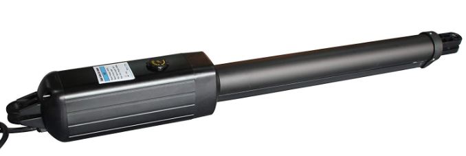
TOPENS Single Swing Gate Opener
Safety Installation Information
- READ and FOLLOW all instruction.
- The gate opener is intended for use with Class I vehicular swing gates. Class I denotes a vehicular gate opener (or system) dwellings, or a garage or parking area associated therewith. Install the gate opener only when the opener is appropriate for the construction and the usage class of the gate.
- Gate opening system designers, installers and users must take into account the possible hazards associated with each individual application. Improperly designed, installed or maintained systems can create risks for the user as well as the bystander. Gate system design and installation must reduce public exposure to potential hazards. All exposed pinch points must be eliminated or guarded.
- A gate opener can create high levels of force during normal operation. Therefore, safety features must be incorporated into every installation. Specific safety features include safety sensors.
- The gate must be properly installed and work freely in both directions prior to the installation of the gate opener.
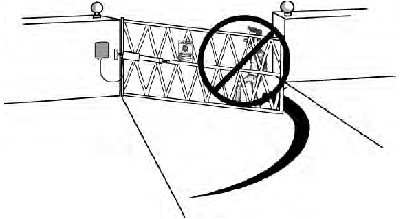
- The gate must be installed in a location so that enough clearance is provided between the gate and adjacent structure when opening and closing to reduce the risk of entrapment. Swinging gates shall not open into public access areas.
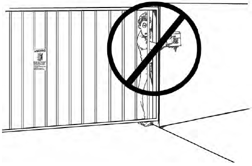
- The opener is intended for use only on gates used for vehicles. Pedestrians must be supplied with a separate access opening. The pedestrian access opening shall be designed to promote pedestrian usage. The pedestrian access shall be located such that persons will not come in contact with the moving vehicular gate.
- Pedestrians should never cross the pathway of a moving gate. The gate opener is not acceptable for use on any pedestrian gate. Pedestrians must be supplied with a separate pedestrian access.
- For an installation utilizing non-contact sensors (safety sensors), see product manual on the placement of non-contact sensors (safety sensors) for each type of application.a. Care shall be exercised to reduce the risk of nuisance tripping, such as when a vehicle trips the safety sensor while the gate is still moving.b. One or more non-contact sensors (safety sensors) shall be located where the risk of entrapment of obstruction exists, such as the perimeter reachable by a moving gate or barrier.
- Never mount any device that operates the gate opener where the user can reach over, under, around or through the gate to operate the controls. Controls are to be placed at least 6’ (1.8m) from any part of the moving gate.
- Controls intended to be used to reset an operator after 2 sequential activations of the entrapment protection device or devices must be located in the line of sight of the gate, or easily accessible controls shall have a security feature to prevent unauthorized use. Never allow anyone to hang on or ride the gate during the entire travel of the gate.
- Each gate opener is provided with two safety warning placards. The placards are to be installed on the front and back of the gate where they are plainly visible. The placards may be mounted using cable ties through the four holes provided on each placard. All warning signs and placards must be installed where visible in the area of the gate.
- To AVOID damaging gas, power, or other underground utility lines, contact underground utility locating companies BEFORE digging. SAVE INSTRUCTION.
- Do not permit children to play on or around the gate and keep all controls out of their react.

Tools Needed:
- Power Drill
- Tape Measure
- Open End Wrenches — 14# &17# or Adjustable Wrenches
- Wire Strippers
- C-Clamps — small, medium, and large
- Level
- Hacksaw or Heavy Duty Bolt Cutters
- Phillips Screwdriver
- An extra person will be helpful
Technical Specifications & Features
| Specifications | |||
| A3(S) | A5(S) | A8(S) | |
| Input: | Adapter Input: 100-240V~ 50/60Hz | ||
| Motor voltage: | 24VDC | ||
| Power: | 30W | 50W | 80W |
| Current: | 1.5A | 2A | 3A |
| Actuator speed: | 16mm/s(0.6 in/s) | ||
| Max. actuator travel: | 385mm(15.2 in) | ||
| Ambient Temperature: | -20℃~ +50℃ (-4°F to 122°F) | ||
| Protection class: | IP44 |
Features:
- Soft start and soft stop
- Emergency release key in case of power failure
- Fast selecting push/pull to open
- Stop in case of obstruction during gate opening.
- Reverse in case of obstruction during gate closing.
- Built in adjustable auto-close (3-120 seconds)
- Built in max. Motor running time (MRT) for multiple safety protection (40 seconds)
- Reliable electromagnetism limit for easy adjustment
- Can be equipped with a wide range of accessories
- Easy to install, and minimum maintenance requirement.
Installation Overview
Preparation for Installation
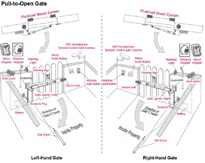
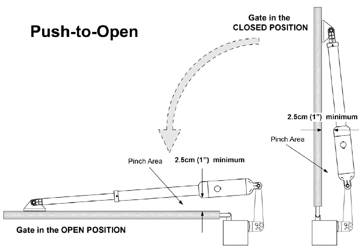
There are two installation types for the gate opener, Pull-to-Open and Push-to-Open. In the Push-to-Open installation, gate opens out from the property. A Push-To-Open Bracket (PSO part) is required to be used
NOTE: Ensure the gate does not open into public areas.
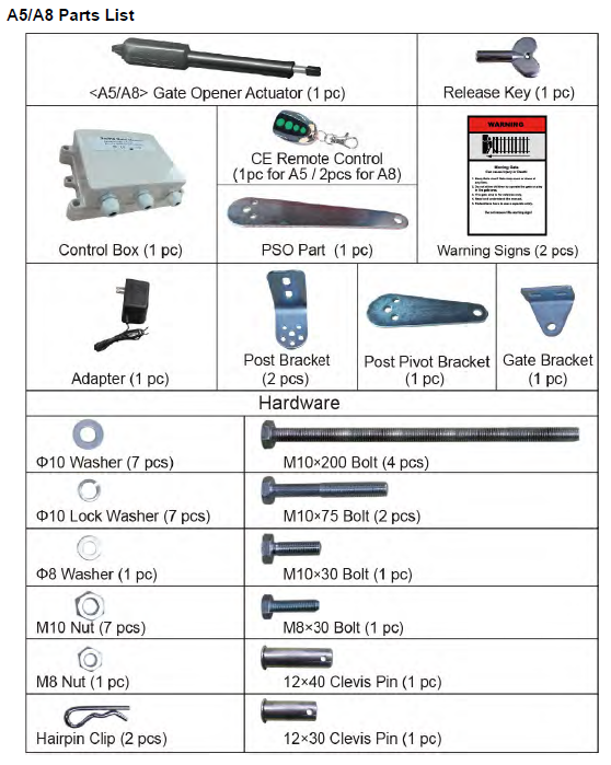
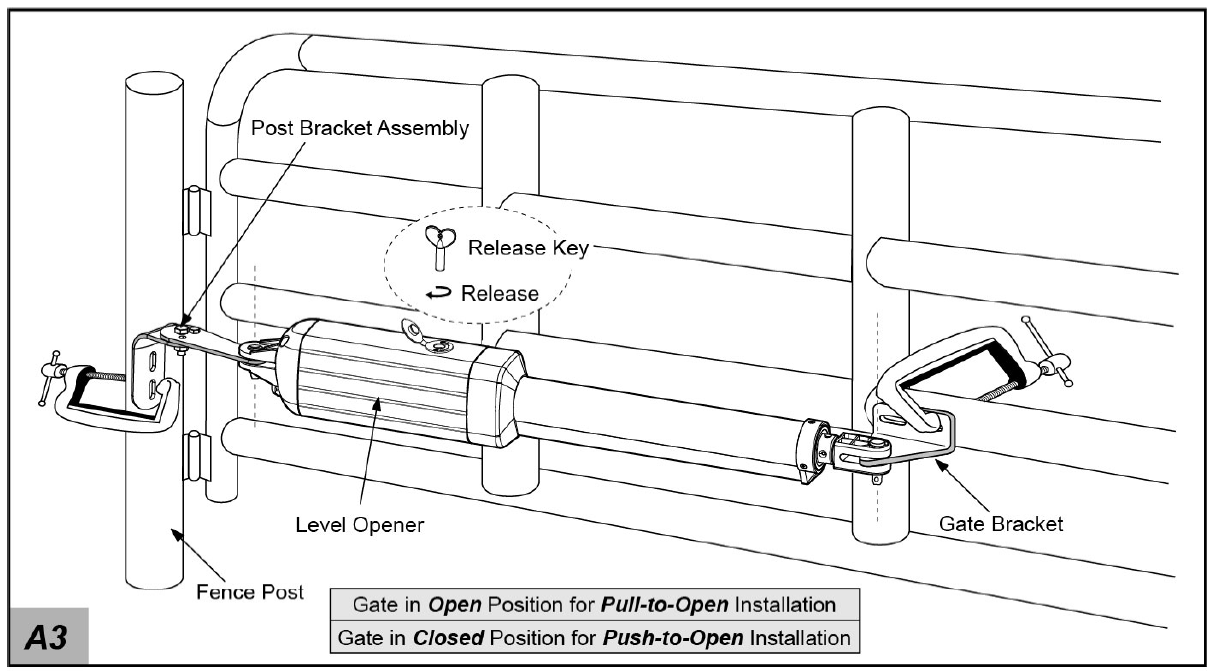
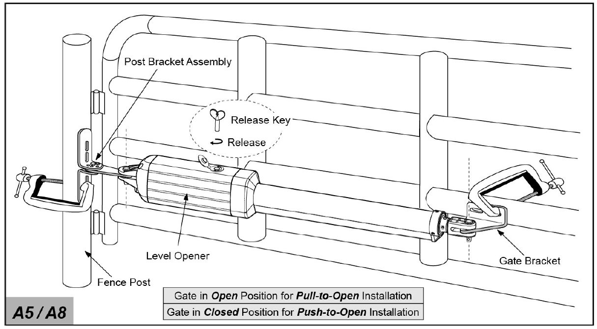
The gate opener is mounted to the gate and to the gate post. Both round and square posts can be used because the Post Brackets are curved. When mounting the Post Brackets, use bolts long enough to pass through the entire post. M10 x 200 bolts are included. Concrete anchors are not provided. When mounting the Post Brackets to wooden posts, a larger-size washer or metal plate should be used between the bolts and the wooden post to ensure the stability of the fastening hardware. If the post is smaller than 6″ diameter or square, it should be made of metal and set in cement to ensure its stability.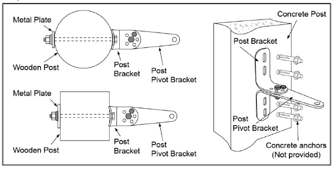
Install the Gate Opener on the Gate
The position of Post Bracket is very important. The following illustrations and tables are required to determine the proper mounting position for the Post Bracket. The tables show the maximum opening angle of the gate for a given A and B. For example, if A is 15cm and B is 20cm, the maximum opening angle of the gate is 110°.Pull-to-Open Installation — Gate in Closed position (Moving-Rod is extended)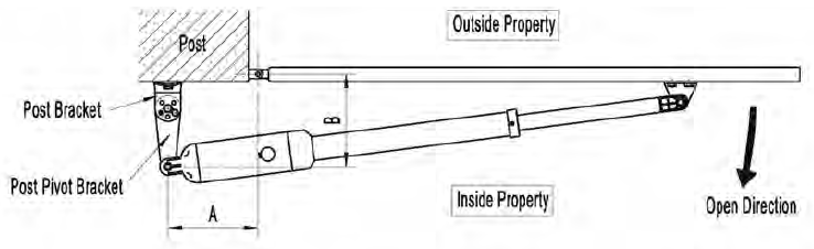
Push-to-Open Installation — Gate in Closed position (Moving-Rod is retracted)
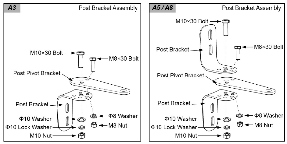
- Insert the M10 x 30 bolt through the center hole of the post bracket and post pivot bracket as shown. Place a ¢10 washer , ¢10 lock washer and M10 nut on the bottom of the bolt and hand tighten.
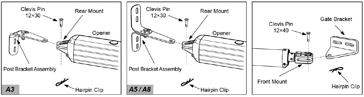
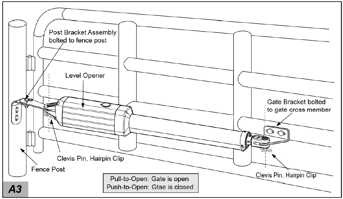
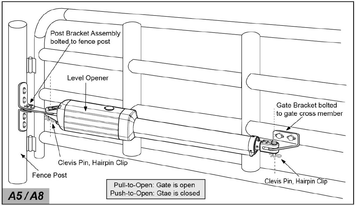
- Attach the gate bracket and post bracket assembly to the opener by inserting a clevis pin. Secure the clevis pins using the hairpin clips.
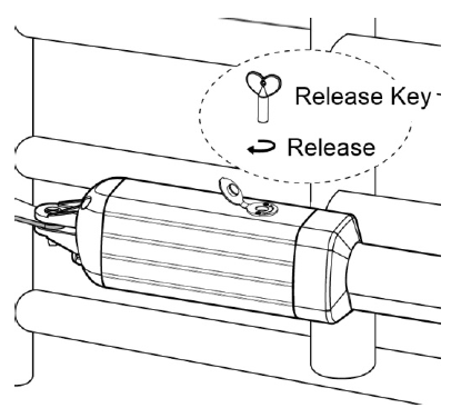
- Open the release hole plug on the top of the gate opener, insert the release key, and turn the key 90° clockwise. This releases the motor and allows the push-pull rod to be manually extended and retracted. To restore normal operation, turn the key 90° counterclockwise.
- With the opener fully retracted and with the gate in the fully open position (for Pull-to-Open installation) or fully closed position (for Push-to-Open installation), place the gate opener with the Post Bracket Assembly and Gate Bracket on the gate post and the gate. Position the Post Bracket Assembly and Gate Bracket so that the gate opener is level. While holding the gate opener in the level position, temporarily secure it with two C-clamps.
- Make sure that there is a minimum clearance of 2.5cm between the gate and the opener and that the opener and the Post Pivot Bracket are not binding in both the gate-open and gate-closed positions. If there is not at least 2.5cm of clearance or if the opener and the Post Pivot Bracket are binding, rotate the Post Pivot Bracket and/or move the Post Bracket Assembly to obtain the minimum clearance and eliminate the binding. When the minimum clearance has been obtained and any binding has been eliminated, place the M8 x 30 bolt through the aligned holes in the Post Bracket and the Post Pivot Bracket.
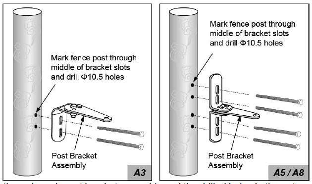
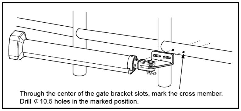
- Sign the bolt-hole point on the gate bracket and gate. Do this by placing a punch or a sign in the middle of each bolt slot on the post bracket assemblies and the gate bracket. It allows slight adjustments to the post bracket. Then remove the post bracket and gate bracket by taking off the C-clamps.
- Drill 10.5 mm diameter holes through the post and the gate at the marked locations.
- 8. Attach the post bracket assemblies to the gate posts by inserting M10 x 200 bolts through each post bracket assembly and the drilled holes in the gate post. Fasten each bolt with one ¢10 washer, one ¢10 lock washer, and one ¢10 nut.
- Attach the gate brackets to each gate by inserting two M10 x 75 bolts through the gate brackets and the drilled holes in the gates. Fasten each bolt with one ¢10 lock washer, and one ¢10 nut.
- Cut off any part of the bolts that extend beyond the tightened nuts.
- With the gate opener fully retracted and with the gate in the fully open position (for Pull-to-Open installation) or fully closed position (for Push-to-Open installation), attach the gate opener to the Post Bracket Assembly and the Gate Bracket by inserting a clevis pin through the gate opener and the Post Pivot Bracket and another clevis pin through the gate opener and the Gate Bracket. Secure each clevis pin with a hairpin clip.
- Open the release hole plug on the top of the gate opener, insert the release key, and turn the key 90° counterclockwise. This restores normal operation.

NOTE: The setting of the PULL/PUSH TO OPEN of the control board should be in accordance with the installation.
Mounting of the Control Box
Use 2 deck screws (not provided) to install the control box. Even though the control box is waterproof designed, for safety reason and a longer service life, it is recommended to install the control box inside a secure surface and at least 100 cm (40 inches) above the ground to avoid being flooded or buried under snow.
Connection of the Power Supply
- The gate opener can be powered by 24V 12Ah battery (NOT INCLUDED) OR DPS180-U AC-DC Power Supply (NOT INCLUDED, available at TOPENS Store). The adapter included in the package is ONLY used to charge the battery.
- Instead of using a battery, the AC-DC Power Supply is highly recommended as the power source to save the cost where AC electricity is accessible and stable.
- If batteries are chosen as the power source, Marine or Automotive Type Battery with capacity greater than 12 Ah is required. The batteries should be waterproof type, or be placed in water proof circumstance.
- 2 PCS 12VDC batteries can be connected in series to function as 24VDC. The following diagram shows on how to connect 2 PCS batteries in series. Charging mode for the battery could be by the adapter, by the solar panel, or both of them at the same time.
- Please note that the wire connection of the power supply system is very important. Incorrect wire connection will damage the control board.
WARNING: NEVER connect the gate opener to the power outlet before all the installations have been done.
Use the batteries as the power source and only use the adapter to charge the batteries
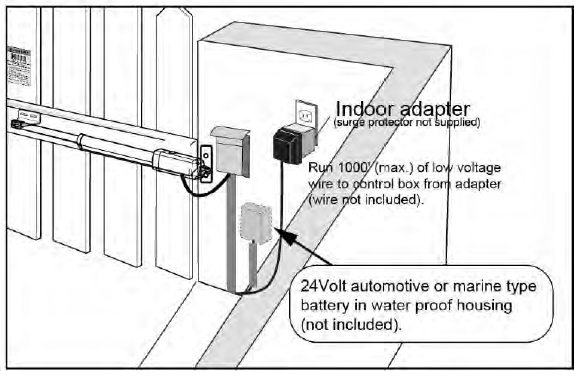
The “24V+” of the battery should be wired to the BAT+ (#11) terminal, “24V-” should be wired to “BAT-” (#12) terminal. The wire [ 2*0.75mm2 (2C*18AWG), 1 meter (3.3 feet) long ] for connecting the battery has been provided and connected to the control board in factory. The adapter should be wired to the “ADAPTER” (#13, #14) terminals of the control board, no matter the polarity. The length of the wire of the adapter is 1.2m (4’). So if the distance between the outlet and the control box is longer than that, you should use an extended wire to connect the adapter to the control board. The wire size should be at least 1.3mm2 (16AWG). If the distance is more than 100m (300’), the wire size should be at least 2mm2 (14AWG). The maximum distance from the adapter to the control box is 300m (1000’).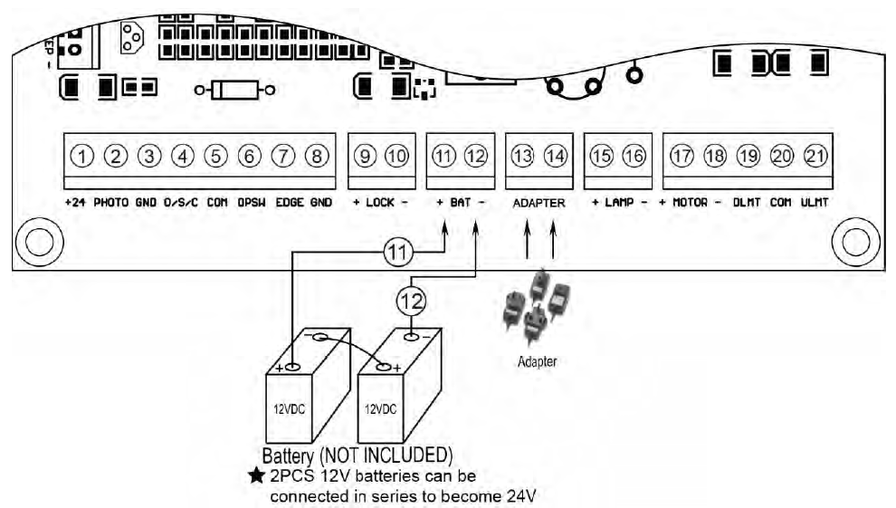
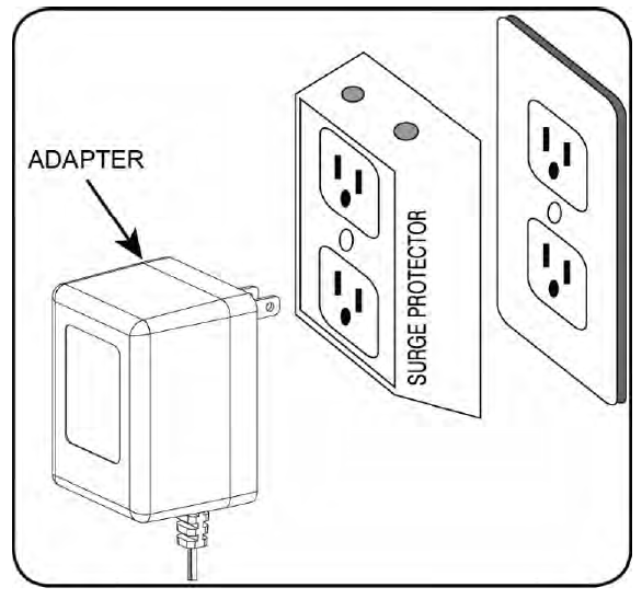
You can plug the adapter into the electrical outlet after all the wire connections are completed. Use a surge protector with the adapter is strongly recommended. If electrical outlet is located outdoors, outlet and adapter should be protected by a weatherproof cover.
Use the batteries as the power source and use the adapter & solar panel to charge the batteries at the same time
If you want to use an optional solar panel to charge the battery with the adapter at the same time, a solar charge controller must be used to control it to charge the battery. You can connect adapter, the solar panel and the solar charge controller refers to the following illustration.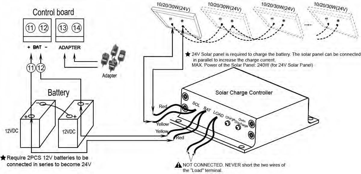
Use the batteries as the power source and only use the solar panel to charge the batteries
If you only use the solar panel to charge the batteries, please note the power of the solar panel should be at least 20W. The gate opener can works for 10 cycles per day if there is no other accessory except photocell & electric lock & push button& alarm lamp connected to the control board. The capacity of the batteries and the power of the solar panel should be enlarged if you want to use more. You can connect the solar panel and the solar charge controller refers to the following illustration.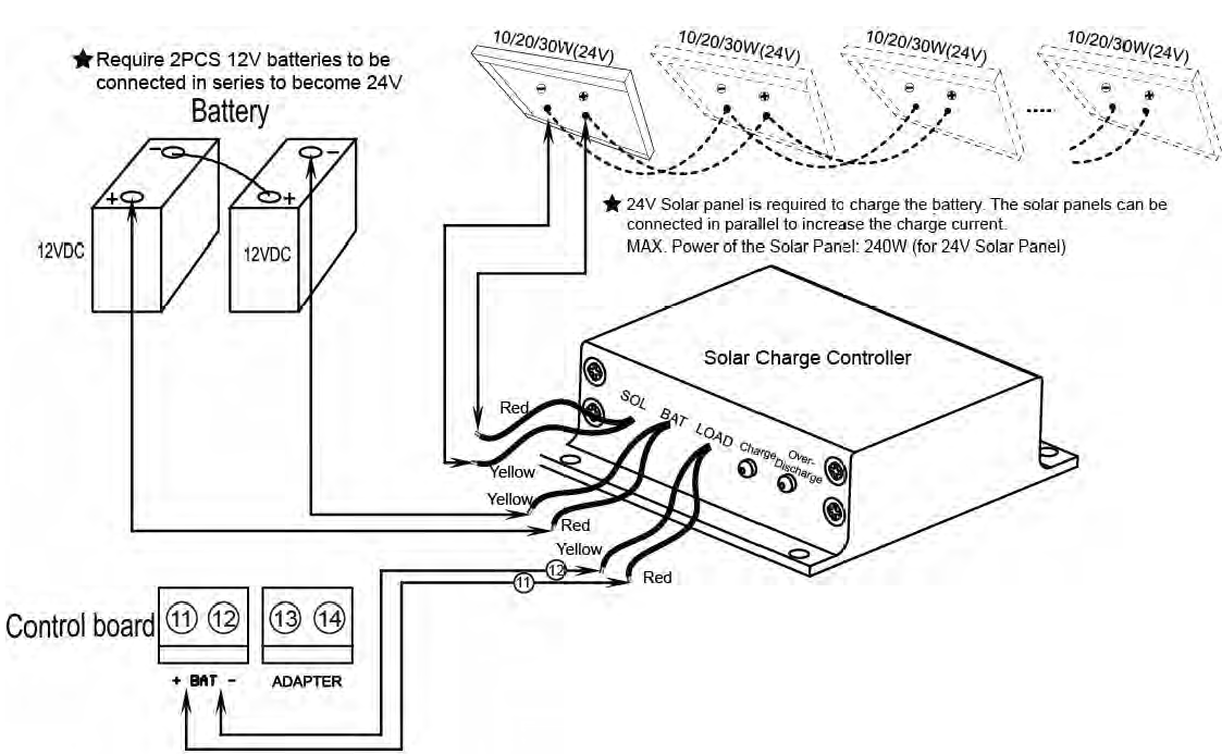
Use the DPS180-U AC-DC power supply as the power source if AC electricity is accessible and stable
The gate opener can be powered by an AC to DC 24V Power Supply (NOT INCLUDED). TOPENS DPS180-U Waterproof AC 110V-240V to DC 24V Power Supply is available at TOPENS Store. Instead of using batteries, this alternative save costs and is strongly recommended. The positive output of the 24VDC power supply should be wired to the BAT+ (#11) terminal, the negative output should be wired to “BAT-” (#12) terminal. There is no need to use the adapter in this situation.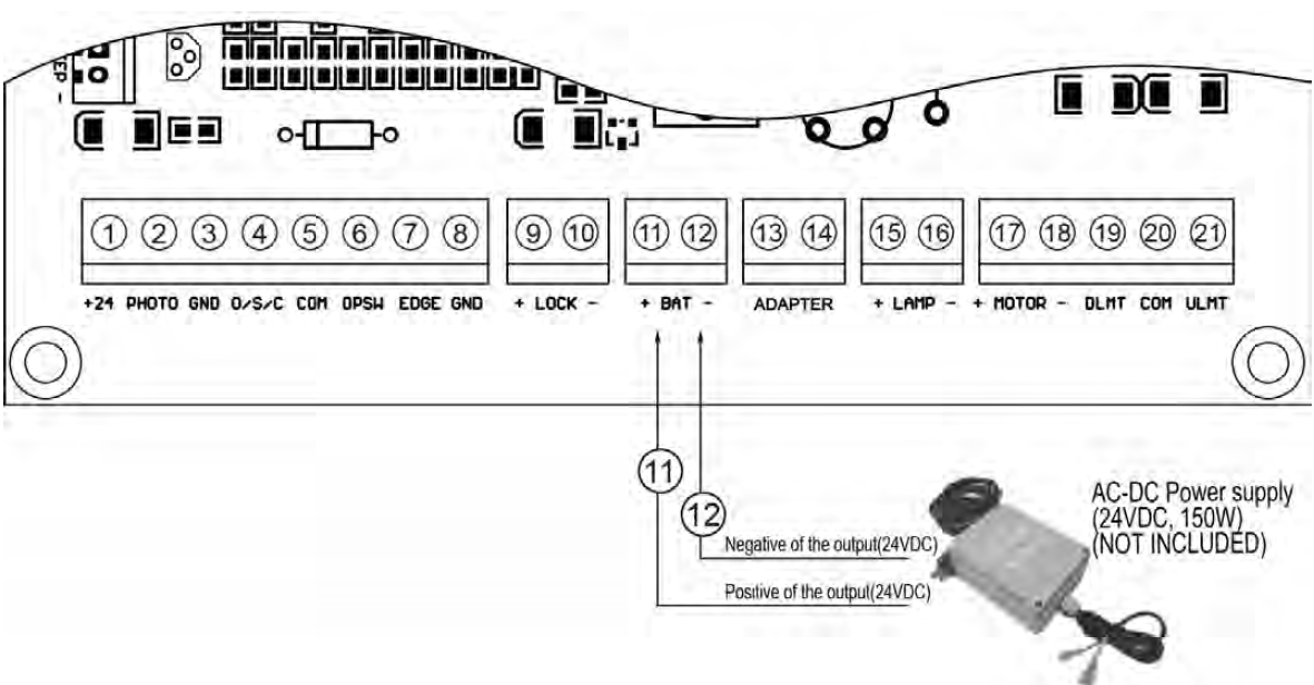
Connection of the Control Board

- ActuatorInsert the stripped cable wires into the appropriate terminals on the opener terminals block. The red wire should be inserted into the “+MOTOR” terminal(#17), the black wire into “MOTOR-” terminal (#18), the blue wire into “DLMT” terminal(#19), the green wire into “COM” terminal(#20), and the yellow wire into “ULMT” terminal (#21).
- Battery OR AC-DC power supply (Required but not included)Please connect them refers to the chapter “Connection of the power supply”.
- Adapter (Only used to charge the batteries)Insert the stripped cable wires into ADAPTER (#13) terminals to the control board. No matter the polarity.
- Warning Light (Included in some models, refers to the actual package)The red wire of the warning light should be inserted into either LAMP (#15) terminal, the white wire into the other one (#16).
- Photocell Beam System (PBS) (Included in some models, refers to the actual package)Use a 2-core cable to connect the “+ ~” terminal of the photocell’s emitter to the “+24”(#1) terminal, the “- ~” terminal to the “GND”(#3) terminal. Also the “+ ~” and “- ~” terminals of the photocell’s receiver should be connected to the “+24” and “GND” terminals in parallel.Use another 2-core cable to connect the “NC” terminal of the receiver to the “PHOTO”(#2) terminal, the “COM” terminal to the “GND”(#3) terminal.
- Push Button (optional)The push button should be wired to the “#4 and “#5” terminals. No matter the polarity. The gate operator works alternately by pressing the button (open-stop-close-stop-open).
- Electric Lock (optional)A lock plus board is required to connect the electric lock to the control board. The 2 wires of J1 of lock plus should be wired to the “9#” and “10#” terminal of the control board. No matter the polarity. Red wire of J2 should be wired to the 11# terminal and yellow wire of J2 should be wired to the 12# terminal of the control board. Red wire of J3 should be connected to the red wire of electric lock and also the yellow wire of J3 should be connected to the yellow wire of electric lock.
- Exit Wand (optional)The BLACK wire of the exit wand should be connected into the “#5” terminal.The BLUE wire of the exit wand should be connected into the “#6” terminal.The RED wire of the exit wand should be connected into the “#11” terminal.The GREEN wire of the exit wand should be connected into the “#12” terminal.The sensitivity adjustment board should be wired to the GREEN wire and the YELLOW wire of the wand. No matter the polarity.
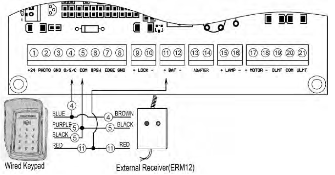
- Wired Keypad (24VDC) (optional)The RED wire of the wired keypad should be connected into the “#11” terminal.The BLACK wire of the wired keypad should be connected into the “#5” terminal.The PURPLE wire of the wired keypad should be connected into the “#5” terminal.The BLUE wire of the wired keypad should be connected into the “#4” terminal.
- External receiver (optional)The RED wire of the external receiver should be connected into the “#11” terminal.The BLACK wire of the external receiver should be connected into the “#5” terminal.The BROWN wire of the external receiver should be connected into the “#4” terminal.
Note: Using of the exit wand, keypad and external receiver would cause the battery exhausted quickly. Big capacity of battery and big power of solar panel(if the solar panel is used as main charger) is required if you want to use either of them.
How to Program the Remote to the Opener
- The remote MUST be programed to the opener BEFORE OPERATING. Please follow the steps to program the remote.
- Activate the opener only when gate is in full view, free of obstruction and properly adjusted. No one should enter or leave gate area while gate is in motion. DO NOT ALLOW CHILDREN to operate push button or remote. DO NOT ALLOW CHILDREN TO PLAY NEAR THE GATE.
- If you purchase additional remote controls, the gate opener must be programmed to accept the new remote code.
- If you lose one of any remote control, please erase and reprogram all other remote controls to have a new code for safety.
Press and release the CODE SW button, the CODE LED will be ON, then press the key in the remote twice in 4 seconds, the CODE LED will flash for 3 seconds and then to OFF. Now the remote has been programmed successfully.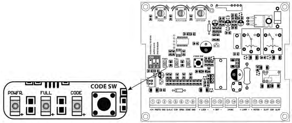
NOTE: Max. 8 remotes can be programmed for the opener. An External Receiver (optional) allows up to 250pcs remotes to be programmed for the opener. TOPENS ERM12 Universal External Receiver is available at TOPENS Store.
TOPENS ERM12 Universal External Receiver is also compatible with other brand swing gate opener, sliding gate opener and garage door opener.
How to Erase All the Remote CodesPress and hold the CODE SW button until the CODE LED from ON to OFF. Now all remote codes have been erased.
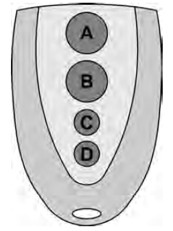
How to Use the Remote to Operate Your Gate OpenerEach remote has four buttons, from top to bottom are separately A, B, C and D. You may use this remote to operate as many as 4 sets TOPENS swing gate openers or 1 set TOPENS sliding gate opener and 2 sets TOPENS swing gate openers.
- Use this remote to only operate TOPENS swing gate opener A, B, C and D four buttons share same function once they are programmed with TOPENS swing gate opener. You may choose any button to program it with our swing gate opener. Every press of the button is able to active the gate opener to work alternately (open-stop-close-stop-open).
- Use one remote to operate TOPENS swing gate opener & sliding gate opener at the same timeAll of TOPENS sliding gate opener have midway mode. Button B is designed to realize midway function (refer to more details in our TOPENS sliding gate opener manual). So it is must program button A with sliding gate opener, while you may program either C button or D button with TOPENS swing gate opener.
Wireless Keypad Programming
You can follow the below steps to program wireless keypad to the opener. Press the CODE SW button until the CODE LED is ON, and then releases the button. Then press “OK” button on keypad and CODE LED will flash for 3 seconds and then be OFF which indicates the keypad has been programmed successfully. You can use the default password “888888” to operate the opener after programming. You can press “PIN” “8 8 8 8 8 8” and then press “OK” to confirm to operate the opener.
Also you can change the password of the keypad follow the below steps. Press “PIN” and then input the six digits old password and then press ”PIN” again, the CODE LED will be ON. Input the six digits new password and then press the “PIN” to confirm the new setting, CODE LED will flash for 3 seconds and then be OFF which indicates the password has been changed successfully. You can press “PIN” “6 digits new password” and then press “OK” to confirm to operate the opener.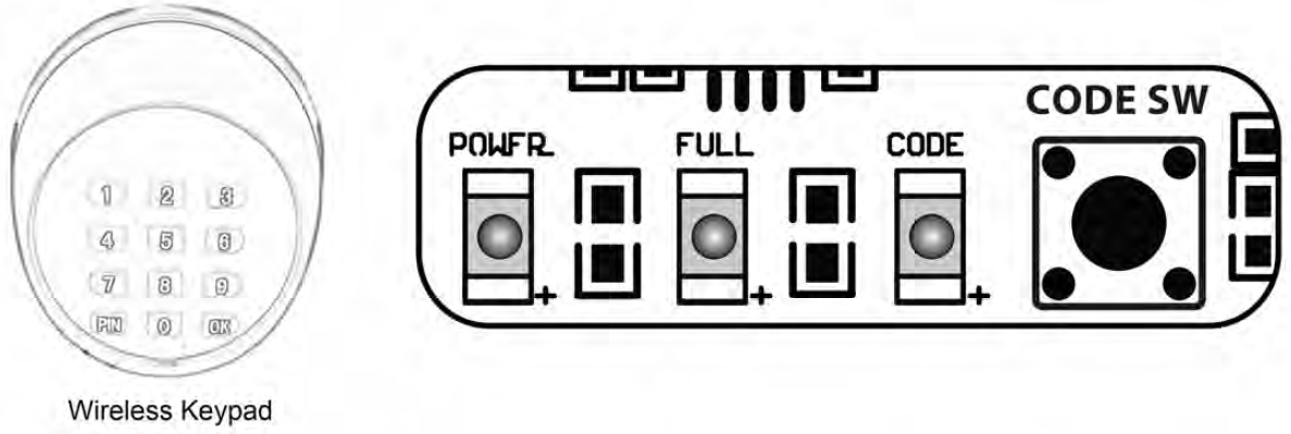
NOTE: Every step for pressing button during program must be finished within 1 second to ensure successful programming.
Adjusting the Limit Switch
The position of Limit Switch A was fixed in factory, do not adjust it again.Plug on the power to running gate opener, use a screwdriver to loosen the screw of Limit Switch B, slide Limit Switch B to the desired closed position and fix it.Limit setting for Gate 1 is finished now.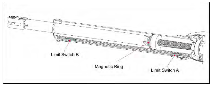 NOTE: Always place the magnetic ring between the Limit Switch A and B.
Setting of the Control Board
WARNING: Ensure the gate opener is Power Off when you make any adjustment of the gate opener. Keep away from the gate during you set the gate opener system in case of the unexpected gate moving. Carefully adjust the DIP switches to avoid the risk of machine damage and injury or death. Always ask the help of professional technician /electrician if you have any question.
DIP Switches
The DIP switches are used to select pull/push to open, enable/disable auto close function, enable/disable photocell function.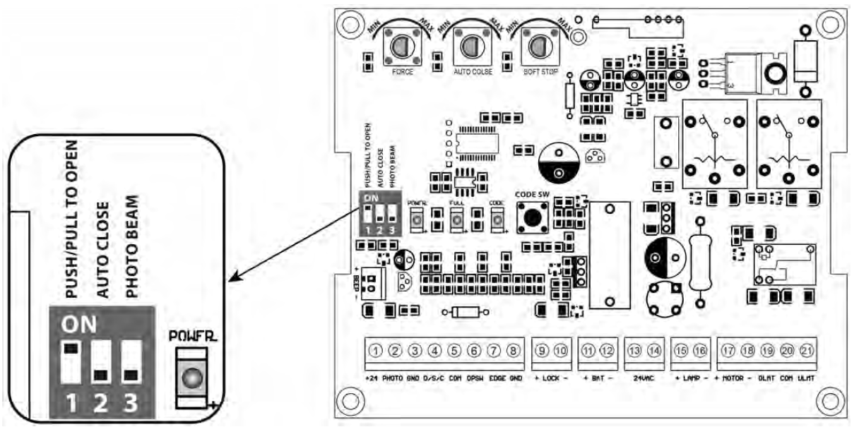
DIP Switch #1: Select push/pull to openIf the gate opens into the property (pull to open), the DIP Switch is set to OFF (factory default setting). If your gate opens out from the property (push to open) the DIP Switch must be set to the ON position.Factory default setting is OFF.
DIP Switch #2: Auto close function enabled/disabledON – Auto close function enabledOFF – Auto close function disabledSet the switch #2 to ON to enable the auto close function. Factory default setting is OFF.
DIP Switch #3: Photocell function enabled/disabledON – Photocell function enabledOFF – Photocell function disabledYou must set the switch #3 to ON to enable the photocell function if you want to use the photocell with the gate opener. Factory default setting is OFF
Potentiometers
There are 3 potentiometers located in the control board. They are used to adjust the stall force, auto-close time and soft stop period.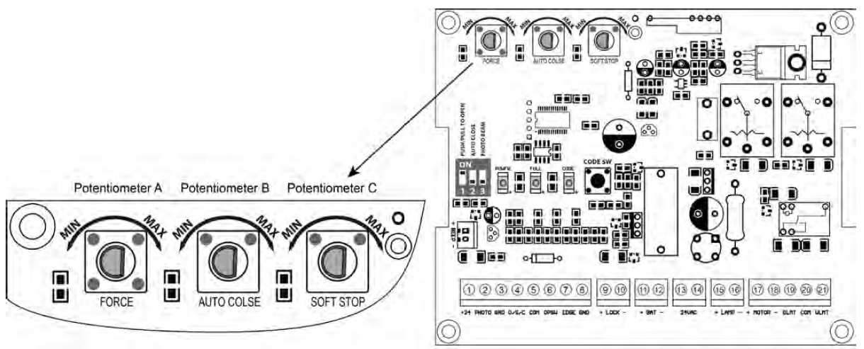
Potentiometer A is used to adjust the stall force the gate opener. Turn the potentiometer clockwise to increase the stall force, and turn it counter-clockwise to decrease the stall force.Potentiometer B is used to adjust the auto close time of the gate opener. Turn the potentiometer clockwise to increase the auto close time, and turn it counter-clockwise to decrease the auto close time. The auto close time can be adjusted steplessly from 3 to 120 seconds.Potentiometer C is used to adjust the soft stop period of the gate opener. Turn the potentiometer clockwise to increase the soft stop period, and turn it counter-clockwise to decrease the soft stop period. The soft stop period can be adjusted steplessly from 1 to 5 seconds.
Maintenance
Warning: Disconnect power before servicing.
- Using a clean, dry cloth to wipe the gate opener shaft, and then apply a silicone spray to reduce its friction. In cold climates where temperatures reach 1°C (30°F) or less, spray silicone on the actuator every 4~6 weeks to prevent freeze up.
- Regularly check gate hinges to make sure gate is swinging smoothly and freely. Grease hinges if needed.
- Check your installation periodically, as hardware and posts will shift. Brackets may need to be adjusted or hardware may need to be tightened.
- Maintain the area around your gate. Keep the areas free of objects that can prevent the gate swinging freely.
NOTES:
- Inspection and service should always be performed anytime a malfunction is observed or suspected.
- It is suggested that while at the site voltage readings be taken at the operator. Using a Digital Voltmeter, verify that the incoming voltage to the opener it is within ten percent of the opener’s rating.
- Refer to the instructions on how to check gate force and sensitivity adjustments.
Trouble Shooting
Have a multi-meter to check voltage and continuity. Use caution when checking high voltage terminals.
| Symptom | Possible Solution(s) |
|
The opener does not run. Only the CODE LED is ON slightly. |
1. The batteries are not connected to the control board or the wire connection of the batteries is loosened. Please note that a 2*12V batteries is required to power up the gate opener. The adapter which is included in the package is only used to charge the batteries. |
| The opener does not run. Power LED flash rapidly (the LED is ON 200ms per second, normally the LED ON 500ms per second). |
1. Battery is over-discharge. Check the voltage of the battery. The voltage of the battery should above 22V to make the gate opener work normally. |
|
The opener does not run. Power LED does not ON. |
1. Make sure the connection between the battery and control board is correct and fastening. 2. Check the fuse in the control board. Replace the fuse if it was burnt out. 3. Check the control board. Replace the control board if necessary. |
|
Gate moves a little and then reverse or stop |
1. The selected force is too small to move the gate. Turn the Potentiometer clock-wise to increase the force.
2. Disconnect the gate from the gate operator and check that the gate slides freely without any binding. |
|
Gate opener does not run when you press the remote control |
1. Make sure the remote has been programmed to the control board before using.
2. The battery of the remote may be exhausted. Replace the battery and try it again. 3. Check if the limit switch is broken. Remove the BLUE&GREEN&YELLOW wires of the arm from the control board and use a jumper wire to short the ULT&COM&DLT terminals of the control board which for connecting the three wires and then try it again. The limit switch of the arm is faulty if the arm could run normally. 4. The control board could be faulty. Replace the control board as necessary. |
|
Gate can open but does not close |
1. Make sure the connection of the photocell beam is not blocked if the photocell is used.
2. Check if the closed limit switch is broken. Remove the BLUE&GREEN&YELLOW wires of the arm from the control board and use a jumper wire to short the ULT&COM&DLT terminals of the control board which for connecting the three wires and then try it again. The limit switch of the arm is faulty if the arm could run normally. 3. The control board could be faulty. Replace the control board as necessary. |
| Gate automatically opens, but does not automatically close |
1. Setting of DIP switch #1 would be wrong. Please set the dip switch correctly according to the push/pull to opener installation of the gate opener. |
![]()
http://www.topenstool.com/Any question, please do not hesitate to contact us:E-mail: [email protected]Kindly include your Product Model, Purchasing Date & Site, Order #,and your contact information. All your concerns will be replied within 24 hours.Tel: +86 (571) 8908 0213 (China)Mon-Fri 9:00AM-5:30PM (UTC +08:00)
References
[xyz-ips snippet=”download-snippet”]