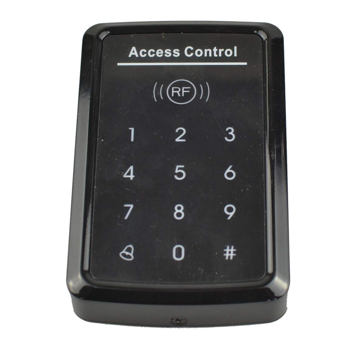
Topens Waterproof Wired Keypad TC175P
 Model: TC175P
Specifications
- Operating voltage: 12-24VDC ±10%
- Operating current: < 100mA
- User Capacity: 1000 users
- Card type (alternative): EM(ID) card(IC card for options)
- Card reading distance: 1-15CM
- Working temperature: -20℃-+50℃
- Relay output: SPDT, 3A 120VAC/24VDC
Factory default settings
- Programming Password: 123456
- Common Access Password: None
- Backlight: Auto (for options)
- Relay Unlock output: 5 Seconds
- W26 port: Input (for options)
- Security mode: OFF
- Open mode: Card or Access Password, Access Password include Private Access Password (PIN) and Common Access Password
Light and Sound indicates
Light: red and green
| Light Description | Access control status |
| Red light flash every 1 sec (Slow flash) | Standby state |
| Red light is always ON | Programming state |
| Green light is always ON within Open time | Unlocking state |
| Green light flash every 0.5sec (Fast flash) | Pending further action |
Buzzer
| Description | Indicates |
| 1 short buzz | Valid input |
| 3 short buzz | Invalid input |
| 1 long buzz | Programming success |
| Continuous long buzz | Restoring factory programming passwords |
Definition of the output wires
JP1 terminal
| NO | Mark | Color | Function |
|
1* |
+12V |
X |
This wire has been cut off |
|
2 |
GND |
Black |
Power-(12-24VDC negative) |
|
3 |
PUSH |
BLUE |
Low level output |
|
4 |
OPEN |
Yellow |
Door Release |
|
5 |
BELL |
Grey |
BELL |
| 6 |
BELL |
White |
BELL |
JP2 terminal
|
NO |
Mark | Color |
Function |
|
1* |
+12V | X |
This wire has been cut off |
|
2 |
GND | Black |
Power-(12-24VDC negative) |
|
3 |
DATA0 | Green |
WG DATA0 |
|
4 |
DATA1 | White |
WG DATA1 |
|
5 |
NC | Brown |
Relay NC output |
|
6 |
COM | Blue |
Relay Com output |
|
7 |
NO | Purple |
Relay NO output |
*NOTE: The red wire of the both 2 terminals has been cut off and it has been soldered to the PCB of the keypad. Thus you can connect the 12-24VDC power supply to the RED wire on the PCB and the BLACK wire of JP2 to power up the keypad.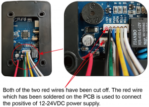
Wire connection of the keypad to the gate & door opener
NOTE: Below wiring diagram is a universal wiring diagram of the connection between the keypad and the opener. You can refer to the user manual of the OPENS gate opener for detailed wiring diagram.
Connect the keypad to the Gate/Door opener with power on the board, when power from the board connected directly to TC175P.
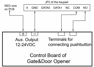
Connect the keypad to the Gate/Door opener without power on the board, when using external power supply for TC175P.In this situation, you need an external 12-24VDC power source to make the keypad to work with the gate & door opener.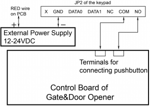
Programming
- There are three kinds of passwords while programming: programming password, access password, card password.
- User ID is auto-generating 4-digit number started at 0001. The number increases with adding user one by one and ignores deleting user. Common Access Password has no ID.
- All passwords can be 3-6 digits in length.
- Programming password is used for programming.
- Access password is used to activate the gate when the keypad has been set to “password” or “password or card” mode.
- Card password is needed to enter after swipe the card when the keypad has been set to “password + card” mode.
- Factory default program password is 123456
How to Change the Programming Password
| # Old Programming Password # 0 New Programming Password # |
How to Set Common Access Password
| # Programming Password # 21 new Common Access Password # |
How to Add Private Access Password (PIN)
| # Programming Password # 22 (3-6 digits access password) # |
NOTE: The quality of access passwords can be set up to 1000 sets. You can input access password and then press # to activate the keypad.
How to Add User Card
| # Programming Password # 1 read card # |
NOTE: If add multi cards, read cards continuously.
How to Delete All Users
| # Programming Password # 40 0000 # |
NOTE: Delete all cards and PIN except Common Access Password.
How to Delete User by Read Card
| # Programming Password # 41 read card # |
NOTE: If delete multi cards, read cards continuously
How to Add Card by Input Card NO.
| # Programming Password # 23 input card NO. # |
NOTE: Card No. is 10-digit or 8-digit, machine auto-identify.
How to Add Multi-card by Input Card NO. Zone
| # Programming Password # 24 input start card No. card Qty # |
NOTE: Card Qty is 4-digit (If one-time add twenty cards, input 0020)
How to Add “card +PIN” User
| # Programming Password # 3 read card PIN # |
NOTE: You can change the PIN according to following instructions. After reading card and input corresponding PIN to open the door, within 5 seconds, long press # until the green lights flash fast. and then input new PIN # new PIN # , new PIN will be changed successfully with a long buzz.
How to Delete User by Input User ID NO.
| # Programming Password # 42 input User ID No. # |
How to Delete User by Input Card NO.
| # Programming Password # 43 input card No. # |
How to Delete User by Input Access Password (PIN)
| # Programming Password # 44 (3-6 digits access password) # |
How to Delete All Access Password (PIN) Users
| # Programming Password # 45 1111 # |
How to Change Open Time
| # Programming Password # 5 XX # |
NOTE: XX can be 2-digit, and the max. is 99. If input 00, the signal output time is 0.2 Second.
How to Set Open Mode
| # Programming Password # 6 XX # |
NOTE: XX can be 01(only card)/ 02(card or Access Password)/ 03(card+PIN)
Reader Setting (For options)
| # Programming Password # 6 04 # |
NOTE: The machine can be used for reader(W26 output)
Security Function Setting, Anti-dismantle Alarm Setting (For options)
| # Programming Password # 7 XX # |
NOTE: XX can be 01/ 02( Security function OFF/ON) and 03/04(Anti dismantle alarm OFF/ON). Security Function ON means System would be locked for 5 Minutes if continue to read illegal card or input wrong Access Password for 10 times.
Backlight setting(For options)
| # Programming Password # 8 XX # |
NOTE: XX can be 01/02 (Normal ON / Normal OFF)
How to Reset Factory Default Setting
| # Programming Password # 8 99 # |
NOTE: Except Programming Password.
Reset to Factory Programming Password(123456)
Step1: Power off the keypad and connect pin 2&3 of RST together.Step2: Power on the keypad and buzzer will give 3 long buzz with green light flashes fast.Step3: Power off the keypad and disconnect pin2&3 and connect pin 1&2 of RST together.Step4: Turn on power again.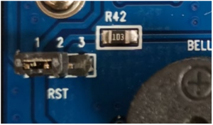
 www.topens.comAny question, please do not hesitate to contact us:E-mail: [email protected]Kindly include your Product Model, Purchasing Date & Site, Order #, and your contact information. All your concerns will be replied within 24 hours.Tel: +86 (571) 8908 0213 (China)Mon-Fri 9:00AM-5:30PM (UTC +08:00)
References
[xyz-ips snippet=”download-snippet”]