
![]()
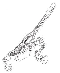
Torin Double Gear Hand Cable Puller Owner’s Manual
REGISTER YOUR PRODUCT
http://www.torin-usa.com/customer-support/register-a-product.html SCAN CODE>

![]() WARNING
WARNING
Questions, problems, missing parts? Before returning to your retailer, call our customer service department at 1-888-44-TORIN (1-888-448-6746), 8 a.m.- 5 p.m., PST, Monday-Friday.
Read carefully and understand all ASSEMBLY AND OPERATION INSTRUCTIONS before operating. Failure to follow the safety rules and other basic safety precautions may result in serious personal injury.
IMPORTANTBefore You Begin Register This Product.For future reference, record the model name, model number, date of manufacture and purchase date of this product. You can find this information on the product.
Model Name:Model Number:Date of Manufacture:Date of Purchase:
OWNER / USER RESPONSIBILITY
DO NOT OPERATE OR REPAIR THIS PRODUCT WITHOUT READING THIS MANUAL. Read and follow the safety instructions. Keep Instructions readily available for operators. Make certain all operators are properly trained and understand how to safely and correctly operate the product. By proceeding you agree that you fully understand and comprehend the full contents of this manual. Failure to operate this product as intended may cause injury or death. The manufacturer is not responsible for any damages or injury caused by improper use or neglect. Allow product operation only with all parts in place and operating safely. Use only genuine replacement parts. Service and maintain the product only with authorized or approved replacement parts; negligence will make the product unsafe for use and will void the warranty. Carefully inspect the product on a regular basis and perform all maintenance as required. Store these instructions in a protected dry location. Keep all decals on the product clean and visible. Do not modify and/or use for any application other than that for which this product was designed. If you have any questions relative to a particular application, DO NOT use the product until you have first contacted the distributor or manufacturer to determine if it can or should be performed on the product.
For technical questions please call 1-888-448-6746.
INTENDED USE
Multi-purpose tool: lifting, lowering, pulling, stretching.Use anywhere: farming, gardening, machine shop, camping, boating, traveling, hobby shop, trucking, fencing, hunting, sports.
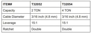
TECHNICAL SPECIFICATIONS
GENERAL SAFETY RULES
![]() WARNING: Read and understand all instructions. Failure to follow all instructions listed below may result in serious injury.
WARNING: Read and understand all instructions. Failure to follow all instructions listed below may result in serious injury.
![]() CAUTION: Do not allow persons to operate or assemble this jack until they have read this manual and have developed a thorough understanding of how the jack works.
CAUTION: Do not allow persons to operate or assemble this jack until they have read this manual and have developed a thorough understanding of how the jack works.
![]() WARNING: The warnings, cautions, and instructions discussed in this instruction manual cannot cover all possible conditions or situations that could occur. It must be understood by the operator that common sense and caution are factors that cannot be built into this product, but must be supplied by the operator.
WARNING: The warnings, cautions, and instructions discussed in this instruction manual cannot cover all possible conditions or situations that could occur. It must be understood by the operator that common sense and caution are factors that cannot be built into this product, but must be supplied by the operator.
SAFETY
Always follow safety precautions when installing and operating this jack. Keep all decals on the unit clean and visible. Before proceeding ensure that you fully understand and comprehend the full contents of this manual. Failure to operate this equipment as directed may cause injury or death. The distributor is not responsible for any damages or injury caused by improper use or neglect.
No single manual can provide instructions for every possible cable pulling application; this manual contains general information necessary to accomplish cable pulls of many different setups.
Safety is essential in the use and maintenance of tools and equipment. This instruction manual and any markings on the tools provide information for avoiding hazards and unsafe practices related to use of this tool. Observe all of the safety information provided.
All specifications are nominal and may change as design improvements occur. Torin Inc. shall not be liable for damages resulting from misapplication or misuse of its products.
SAFETY MARKINGS
![]() WARNING!
WARNING!
- Study, understand, and follow all instructions before operating this device.
- Do not exceed rated capacity.
- Be aware of dynamic loading! Sudden load movements may briefly create excess load causing product failure.
- Do not operate while puller is restricted from forming a straight line with loading direction.
- Do not operate puller with twisted, kinked, or damaged wire rope. Inspect wire rope carefully before every use.
- Do not operate a damaged or malfunctioning puller. Inspect puller carefully and test operation before every use.
- Do not use for vertical lifting. Do not lift people. Do not lift loads over people. Unsafe, tilting, or falling loads can injure or kill people.
- Do not operate puller with a lever extension.
- Do not operate with wire rope not centered in pulley groove.
- Do not remove or cover warning labels and/or tags, these carry important safety information.
- No alterations shall be made to this product.
- Only attachments and/or adapters installed by the manufacturer shall be used.
- Do not use this product for any use other than the manufacturer specified usage.
- Failure to heed these markings may result in personal injury and/or property damage.
![]() SAFETY ALERT SYMBOLThis symbol is used to call your attention to hazards or unsafe practices which could result in an injury or property damage. The signal word, defined below, indicates the severity of the hazard. The message after the signal word provides information for pre-venting or avoiding the hazard.
SAFETY ALERT SYMBOLThis symbol is used to call your attention to hazards or unsafe practices which could result in an injury or property damage. The signal word, defined below, indicates the severity of the hazard. The message after the signal word provides information for pre-venting or avoiding the hazard.
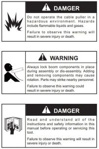
![]() DANGER
DANGER
Immediate hazards which, if not avoided, WILL result in severe injury or death.
![]() WARNING
WARNING
Hazards which, if not avoided, COULD result in severe injury or death.
![]() CAUTION
CAUTION
Hazards or unsafe practices which, if not avoided, MAY result in injury or property damage.
IMPORTANT SAFETY INFORMATION
![]() WARNING
WARNING
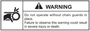
An under-rated or worn rope may break and whip violently. Use a double-braided composite rope with the following characteristics:
Failure to observe this warning could result in severe injury or death.
![]() WARNING
WARNING
- Check the condition of the entire rope before use. A worn or damaged rope can break under tension and whip violently.
- Do not maintain a stationary rope on a rotating capstan.
The wear generated may cause the rope to break under tension and whip violently.Failure to observe these warnings could result in severe injury or death.
![]() WARNING
WARNING
Attach the pulling rope to the cable with appropriate types of connectors as supplied by manufacturer.Select connectors have a maximum-rated capacity.An under-rated connector can break under tension.Failure to observe this warning could result in severe injury or death.
![]() WARNING
WARNING
- Do not allow any unnecessary personnel to remain in the area during the pull.
- Do not allow any personnel to stand in line with the pulling rope.
Rope, cable, or a connecting device can break under tension, causing the rope to whip violently.Failure to observe these warnings could result in severe injury or death.
![]() WARNING
WARNING
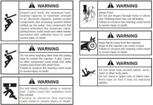
Do not allow the rope to become overlapped on the capstan. If an overlap begins to develop, relax the tailing force immediately and shut off the cable puller.
Failure to observe this warning could result in severe injury or death.
![]() WARNING
WARNING
Use this tool for manufacturer’s intended purpose only. Do not use the cable puller as a hoist or winch.
- The cable puller cannot lower a load.
- The load may fall.
Failure to observe this warning could result in severe injury or death.
![]() WARNING
WARNING
Inspect puller and accessories before use. Replace any worn or damaged components with manufacturer replacement parts. A damaged or improperly assembled item can break and strike nearby personnel with sufficient force to cause severe injury or death.
![]() WARNING
WARNING
Entanglement hazard:
- Do not operate the cable puller while wearing loose- fitting clothing.
- Retain long hair.
Failure to observe this warning could result in severe injury or death.
Cable Pulling Glossary
Anchoring systemAny item or group of items that keeps a cable pulling component in place during the cable pull.
CapstanThe hollow cylinder of the cable puller that acts on the pulling rope to generate pulling force.
Coefficient of frictionThe ratio that compares two amounts of force: (1) the force needed to move an object over a surface and (2) the force holding the object against the surface.
This ratio is used to describe how the capstan and the rope work together.
ConnectorAny item, such as a wire grip, clevis, swivel, or pulling grip, that connects the rope to the cable.
Direct line of pullThe areas next to the pulling rope and along its path; this includes the areas in front of, in back of, and underneath the rope.
Maximum rated capacityThe amount of pulling tension that any component can safely withstand, rated in kilonewtons (metric) or pounds; the maximum rated capacity of every component must meet or exceed the maximum pulling force of the cable puller.
Newton (N)A metric unit of force, equivalent to 0.225 pounds of force.
Pipe adapter sheaveAttaches to conduit for pulling or feeding cable.
Pulling gripConnects the rope to the cable; consists of a wire mesh basket that slides over the cable and grips the insulation.
Pulling forceThe amount of pulling tension developed by the cable puller, rated in newtons (metric) or pounds; a cable puller is usually described by the maximum pulling force that it can develop.
Resultant forceAny force that is produced when two or more forces act on an object; applies to the sheaves of a cable pulling system.
Rope rampA device that works with a tapered capstan; guides the rope onto the capstan to prevent rope overlap.
SheaveA pulley that changes the direction of the rope and cable.
Stored energyThe energy that accumulates in the pulling rope as it stretches, described in newton-meters (metric) or foot-pounds.
Support structureAny stationary object that a cable pulling system component is anchored to, such as a concrete floor (for the floor mount) or an I-beam (for a sheave).
Tactile feedbackThe way the rope feels as it feeds off of the capstan; the feel of the rope provides information about the progress of the pull to the operator.
TailThe portion of the rope that the operator applies force to; this is the rope coming off of the capstan, and is not under the tension of the pull.
Tailing the ropeThe operator’s main function; this is the process of applying force to the tail of the pulling rope—refer to the complete explanation under “Cable Pulling Principles”.
Wire gripConnects the rope to the cable; some use a set screw to clamp onto the conductors of the cable.
CABLE PULLING PRINCIPLES
Pulling cable is a complex process. This section of the manual describes and explains four main topics of pulling cable:
- Each cable pulling system component
- How these components work together
- Forces that are generated
- Procedures for the cable puller operator to follow
While reading through this section of the manual, look for components that are shaded in the illustrations. The shading indicates components that are associated with the text.
Greenlee strongly recommends that each member of the cable pulling crew review this section of the manual before each cable pull.
Cable Pulling SystemsPulling cable requires a system of components. At a minimum, a cable pulling system will include a cable puller, a cable pulling rope, and connectors to join the rope to the cable. Most systems will also include, but are not limited to, a cable puller anchoring system, pulling sheaves and sheave anchoring systems.
The cable puller has a maximum amount of pulling force, which is the amount of pulling tension that it develops. Every other component of the pulling system has a maximum rated capacity, which is the amount of pulling tension that it can withstand. The maximum rated capacity of every component must meet or exceed the cable puller’s maximum pulling force.
Pulling TheoryThis section introduces the main ideas involved with pulling cable.
Pulling ResistanceThe cable puller must overcome two types of resistance: gravity and friction.Gravity constantly exerts its force on the vertical portions of the run. When the pulling force is relaxed, gravity attempts to pull the cable downward. Friction develops where the cable contacts the sheaves, conduit and tray. Friction resists any movement, forward or backward, and tends to hold the cables in place.
To accomplish a cable pull, the cable pulling system must develop more force than the combination of gravity and friction.
Generating Pulling ForceTo generate pulling force, the capstan works as a force multiplier. The operator exerts a small amount of force on the rope. The cable puller multiplies this and generates the pulling force.This pulling force is applied to the rope, connectors, and cable in order to accomplish the pull. The direc-tion of force is changed, where necessary, with pulling sheaves.
At the Pulling RopeThe product of a force (f) moving through a distance (d) is energy (f x d), and may be measured in newton-meters or ft-lb. Energy is stored in a rope when the rope is stretched. This is similar to the way energy is stored in a rubber band when it is stretched. Failure of the rope or any other component of the pulling system can cause a sudden uncontrolled release of the energy stored in the rope.
For example, a 100 meter nylon rope with a 50,000 newton average breaking strength could stretch 40 meters and store 1,000,000 joules of energy. This is enough energy to throw a 900 kilogram object, such as a small automobile, 113 meters into the air.
A similar double-braided composite rope could store approximately 300,000 joules of energy. This could throw the same object only 34 meters into the air. The doublebraided omposite rope stores much less energy and has much less potential for injury if it were to break.
Double-braided composite rope is the only type of rope recommended for use with the Ultra Tugger cable puller. Select a double-braided composite rope with an average rated breaking strength of at least 143 kN (32,000 lb).
CABLE PULLING PRINCIPLES
At the ConnectorsThe connectors will be subjected to the cable puller’s maximum pulling force.
Several types of rope connectors—clevises, swivels, and rope-to-swivel connectors—are available. Follow the instructions provided with each to provide a good connection.
Two types of wire connectors—wire grips and pulling grips—are available. The wire grip uses a set screw to clamp onto the conductors of the cable. The pulling grip consists of a wire mesh basket that slides over the cable and grips the insulation.
When selecting a pulling grip, it is extremely important to select a grip of the correct (1) type, (2) size, and (3) maximum rated capacity.
At the SheavesSheaves are used to change the direction of the pull. A change in direction creates a new resultant force that may be greater than the cable puller’s maximum pulling force. This new resultant force exerts itself on the sheaves, sheave anchoring system, and support structures illustrated.
The resultant amount of force depends on the angle of the change in direction.
Tailing the RopeThe rope must be pulled off of the capstan as the pull progresses. The rope that has left the capstan is the “tail.” The process of pulling the rope off of the capstan is called tailing the rope.
The resistance of the cable varies throughout the dura-tion of the cable pull. Changes in resistance are due to characteristics of the rope, changes in conduit direction, and changes in the amount of friction. The “feel” of the rope provides this information about the pull. This is called tactile feedback. Adjust the tailing force as necessary to compensate for these changes.
Control of the PullDecreasing the tailing force will decrease the pulling force, until the rope slips on the capstan and the pull stops. This provides a high level of control over the progress of the cable pull.
Do not allow the rope to slip on the capstan for more than a few moments. If it becomes necessary to completely stop a pull, shut off the puller and maintain enough tailing force to hold cable in place. Tie the rope off to hold it in place.
Amount of Tailing ForceWhile the rope and cable are under tension, it is impor-tant to maintain the proper amount of tailing force. Too little tailing force will allow the rope to slip on the capstan. This will build up excessive heat and accelerate rope wear, increasing the possibility of breaking the rope.
The proper amount of tailing force will stop the rope from slipping on the capstan and produce a sufficient amount of pulling force to pull in the rope and cable.
Too much tailing force is any amount more than is necessary to stop the rope from slipping on the capstan. Excessive tailing force will not increase the pulling force or pulling speed.
Number of Wraps of Rope Around the CapstanAn experienced operator should choose the number times the rope is wrapped around the capstan.
The proper number of wraps allows the operator to control the progress of the pull with a comfortable amount of effort.
Using too few wraps requires a large tailing force to accomplish the pull. Using too few wraps also makes the rope more likely to slip on the capstan. This builds up heat and accelerates rope wear. Using too many wraps causes the rope to grab the capstan tighter. This accelerates rope wear, wastes power, and increases the possibility of a rope overlap. Using too many wraps also reduces tactile feedback, so you receive less information about the pull. You cannot quickly relax the tailing force when there are too many wraps.
If the rope becomes difficult to tail, add another wrap of rope. Turn off the puller and release all of the tension in the rope. Add a wrap and resume pulling. Be aware, however, that some pulls will require tension to hold the cables in place. In these cases, do not attempt to release all of the tension and add a wrap of rope. You will need to anticipate the number of wraps before starting the pull.
CABLE PULLING FORCES
Cable Pulling ForcesThis section provides detailed explanations and illustrations of the forces that are generated during the cable pull. These explanations are based on the concepts presented in the last section, “Pulling Theory.”
At the Cable Puller Anchoring SystemThe cable puller will exert its maximum pulling force on cable puller’s anchoring system. It is extremely important the anchoring system can withstand this amount of force. Refer to the instruction manual provided with your anchoring system for proper setup or installation.
At the CapstanThe capstan acts as a force multiplier. The operator exerts a small amount of tension, or tailing force, on the rope; the capstan multiplies this force to pull the cable.
The resultant force depends upon the number of times the rope is wrapped around the capstan, as shown in the formula below.
Pulling Force = Tailing Force x e0.0175μøWhere:
e = the natural logarithm, or 2.7183μ = the coefficient of friction between the rope and the capstan*ø = the number of degrees of wrap of rope around the capstan
* The average value for the coefficient of friction when double-braided composite rope is pulled over a clean dry capstan is 0.125.
The following table is based on the formula above.The input, or tailing force, is constant at 44.5 N (10 lb). Increasing the number of wraps increases the pulling force.
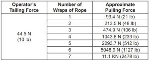
This table shows how the capstan acts as a force multiplier. Because the coefficient of friction depends upon the condition of the rope and capstan, this formula cannot determine an exact amount of pulling force.
PREVENTING ROPE OVERLAP
Do not allow the rope to become overlapped on the capstan during a pull.
A rope overlap will make it will impossible to continue or back out of the pull.
If the rope becomes overlapped, you will lose control of the pull — the rope will advance with no tailing force and will not feed off of the capstan. The capstan will not allow you to reverse the direction of the rope, so you cannot back out of an overlap.
Set up the puller properly. The rope ramp and tapered capstan are intended to prevent rope overlap. Refer to the instructions in the “Operation” section of this manual.
Every wrap of the rope must remain in direct contact with the capstan. During the pull, take great care to prevent the incoming rope from riding up and overlap-ping the next wrap. If an overlap begins to develop, immediately relax the tailing force on the rope so that the rope can feed back toward the conduit or tray. When the rope resumes its normal path, apply tailing force and continue the pull.
There is no suggested remedy for a rope overlap.Do not allow the rope to overlap!
Summary of Cable Pulling Principles
- A cable pulling system consists of many components that work together to accomplish a pull.
- The cable puller is rated by its maximum pulling force; every other component is rated by its maximum rated capacity. The maximum rated capacity of every component must meet or exceed the maximum pulling force of the cable puller.
- The cable puller must overcome two types of resis-tance: gravity and friction. The puller’s capstan, the pulling rope, and the operator tailing the rope work together to produce pulling force.
- The cable puller exerts force on every component of the cable pulling system, including the anchoring systems and the support structures.
- Energy is stored in a rope when the load causes the rope to stretch. Failure of the rope or any other component can cause a sudden release of energy. Replace any rope that is worn or damaged.
- Carefully select the number or wraps of rope around the capstan before starting the pull.
- Control the pull by tailing the rope. Be familiar with the interaction of the rope and capstan.
- Do not allow a rope overlap to develop.
- Pull in a direction that will require the lowest amount of pulling force.
- Plan several shorter pulls rather than fewer longer pulls.
- Locate the puller as close to the end of the conduit as possible to minimize the amount of exposed rope under tension.
- Place each component so that the pulling forces are used effectively.
- Select an anchoring system: adapter sheaves, which are preferred, or the floor mount.
- Verify that each component has the proper load rating.
- Inspect the structural supports. Verify that they have enough strength to withstand the maximum forces that may be generated.
GENERAL SAFETY RULESIMPORTANT SAFETY CONSIDERATIONS
EQUIPMENT USE
These figures do not include a coefficient of friction. Loads that do not have wheels or some smooth means of rolling, will require significantly more power to pull, so loads will have to be much lighter than the 4,000 lb example above.
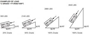
DO NOT EXCEED 180% GRADE WHEN PULLING ANY WEIGHT LOAD.THIS PRODUCT IS NOT DESIGNED FOR LIFTING.
WINDING THE CABLE
- Fish the rope through the conduit.
- Set up the cable puller. Refer to Typical Setups illustrations and instructions in this manual.
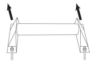
- Set the rope ramp as follows:
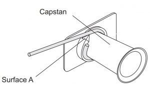
- Wind the rtohpee several times around th capstan.
- Pull the ramp away from the mounting plate and rotate it until Surface A contacts the rope.
- Push the rope toward the mounting plate and rotate it counterclockwise until it locks into place tight.
- Secure the the rope and connector fittings that anchor the cable.
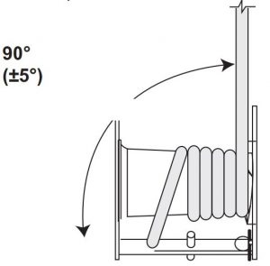
 WARNING
Set up the cable puller so that the rope will approach the capstan at an angle of 90° (±5°). Angles outside of this range may cause the rope to overlap.
REMOVING CABLE
Removing old cable involves the same principles as installing new cable. However, there are some important differences.
Pulling ForceIt is difficult to predict the amount of pulling force necessary to remove an old cable. The cable may be damaged, and it may break with an unexpectedly low pulling force.
The required pulling forces may be very high:
- The cable has probably “taken a set.” Unlike the new cable on a reel, cable in conduit has probably been in the conduit for years, or perhaps decades. The cable will resist bending and straightening as it is pulled through the conduit.
- The pulling lubricant has probably hardened, increasing pulling resistance.
- The insulation may be damaged and the cable may be corroded.
- Dirt or other foreign matter may have entered the conduit and may have cemented the cable in place.
Using a Force GaugeWhen pulling old cable out of a conduit, the pulling force will be highest when starting the pull. Select a cable puller and pulling components to meet or exceed the estimated amount of pulling force necessary to remove the old cable. Because breaking the cable free will require the largest amount of pulling force,do not exceed overloading the system components.
Carefully monitor the pulling force; if the puller is not able to begin the pull, start over with a puller and components of a higher force rating.
Puller PlacementPulling out old cable is generally accomplished with the puller located some distance away from the end of the conduit. This allows the you to pull out a long section of cable before, cutting off the cable, and reattaching the grip(s). Mounting the cable puller a distance away from the end of the conduit increases the amount of exposed rope, which greatly increases the amount of violent whipping action which would occur if the rope were to break.
To isolate the operator from the rope path:
- Locate the puller so that you will stand behind an obstruction, such as a wall. Set up the puller so that you will be able to maintain control of the pull. You need a clear view of the rope as it feeds onto the capstan, including several feet of the rope in front of the capstan.You must be able to turn off the puller before the pulling grip, connector, or swivel contacts the capstan.
- Use an additional pulling sheave (if necessary) to change the direction of the tailing rope. Anchor the sheave so that you are close enough to maintain control of the pull. You need a clear view of the rope as it feeds onto the capstan, including several feet of the rope in front of the capstan. You must be able to stop the puller before the pulling grip, connector, or swivel contacts the capstan.Note: Use an additional pulling sheave to change the direction of the tailing rope (after the rope leaves the capstan). Do not change the direction of the pulling rope.
- Locate the puller so that you will stand behind an obstruction, such as a wall. Set up the puller so that you will be able to maintain control of the pull. You need a clear view of the rope as it feeds onto the capstan, including several feet of the rope in front of the capstan. You must be able to turn off the puller before the pulling grip, connector, or swivel contacts the capstan.
- Use an additional pulling sheave (if necessary) to change the direction of the tailing rope. Anchor the sheave so that you are close enough to maintain control of the pull. You need a clear view of the rope as it feeds onto the capstan, including several feet of the rope in front of the capstan. You must be able to turn off the puller before the pulling grip, connector, or swivel contacts the capstan.Note: Use the additional pulling sheave to change the direction of the tailing rope (after the rope leaves the capstan). Do not change the direction of the pulling rope.
- Use a longer tailing rope than usual and stand away from the puller. Stand as far from the puller as possible, while maintaining control of the pull. You need a clear view of the rope as it feeds onto the capstan, including several feet of the rope in front of the capstan. You must be able to turn off the puller before the pulling grip, connector, or swivel contacts the capstan.
MAINTENANCE INSTRUCTIONS
If you use and maintain your equipment properly, it will give you many years of service. Follow the maintenance instructions carefully to keep your equipment in good working condition. Never perform any maintenance on the equipment while it is under a load.
InspectionYou should inspect the product for damage, wear, broken or missing parts (e.g.: pins) and that all components function before each use. Follow lubrication and storage instructions for optimum product performance.
BindingIf the product binds while under a load, use equipment with equal or a larger load capacity to lower the load safely to the ground. After un-binding; clean, lubricate and test that equipment is working properly. Rusty components, dirt, or worn parts can be causes of binding Clean and lubricate the equipment as indicated in the lubrication section. Test the equipment by lifting without a load. If the binding continues contact Customer Service.
CleaningIf the moving parts of the equipment are obstructed, use cleaning solvent or another good degreaser to clean the equipment. Remove any existing rust, with a penetrating lubricant.
LubricationThis equipment will not operate safely without proper lubrication. Using the equipment without proper lubrication will result in poor performance and damage to the equipment. Some parts in this equipment are not self-lubricating inspect the equipment before use and lubricate when necessary. After cleaning, lubricate the equipment using light penetrating oil, lubricating spray.
- Use a good lubricant on all moving parts.
- For light duty use lubrication once a month.
- For heavy and constant use lubrication recommended every week.
- NEVER USE SANDPAPER OR ABRASIVE MATERIAL ON THESE SURFACES!
Rust Prevention:Check rams and pump plungers on the power unit assemblies daily for any signs of rust or corrosion. Without a load lift the equipment as high as it goes and look under and behind the lifting points. If signs of rust are visible clean as needed.
Grease FittingsSome models contain grease fittings the will regularly need to be greased and lubricated.
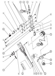
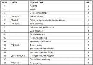
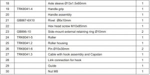
ASSEMBLY DIAGRAM-T32052

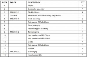
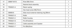
ASSEMBLY DIAGRAM-T32054
WARRANTY NOTICE
This equipment is covered under a 1-year limited warranty when used as recommended. Only those items listed with a Part # are available for purchase. For assistance with the operation or the availability of replacement parts, contact our Parts and Warranty Department at 1-888-44-TORIN (1-888-448-6746). Please have available a copy of your receipt, the model number of the product, serial number, and specific details regarding your question.
Not all equipment components are available for replacement; illustrations provided are a convenient reference of location and position in the assembly sequence.
The manufacturer reserves the rights to make design changes and or improvements to product lines and manuals without notice.
WARRANTY INFORMATION
We want to know If you have any concerns with our products. If so, please call toll-free for Immediate assistance. For additional web customer support help inquiries visit the Customer Service section at: http://www.torin-usa.com.
TORIN ONE YEAR LIMITED WARRANTY
Torin Inc.® has been producing quality automotive repair and maintenance products since 1968. All products sold are felt to be of the highest quality and are covered by the following warranty:With proof of purchase for a period of one year from the date of that purchase, the manufacturer will repair or replace, at its discretion, without charge, any of its products or parts thereof which fail due to a defect in material or workmanship. This warranty does not cover damage or defects caused by improper use, careless use or abuse of the equipment. This warranty does not cover parts normally considered to wear out or be consumed in the normal operation of the equipment.
Except where such limitations and exclusions are specifically prohibited by applicable law, (1) the CONSUMERS SOLE AND EXCLUSIVE REMEDY SHALL BE THE REPAIR OR REPLACEMENT OF DEFECTIVE PRODUCTS AS DESCRIBED ABOVE, and (2) THE MANUFACTURER SHALL NOT BE LIABLE FOR ANY CONSEQUENTIAL OR INCIDENTAL DAMAGE OR LOSS WHATSOEVER, and (3) THE DURATION OF ANY AND ALL EXPRESSED AND IMPLIED WARRANTIES, INCLUDING, WITHOUT LIMITATION, ANY WARRANTIES OF MERCHANTABILITY AND FITNESS FOR A PARTICULAR PURPOSE, IS LIMITED TO A PERIOD OF ONE YEAR FROM DATE OF PURCHASE.
Product alteration in any manner by anyone other than us, with the sole exception of alterations made pursuant to product instructions and in a workman like manner. You acknowledge and agree that any use of the product for any purpose other than the specified use(s) stated in the product instructions is at Your own risk.
Always check for damaged or worn out parts before using any product. Broken parts will affect the equipment operation. Replace or repair damaged or worn parts immediately. Do not modify the product in any way. Unauthorized modification may impair the function and/or safety and could affect the life of the equipment. There are specific applications for which products are designed and tested during production. Manufacturer provided warranted items are not authorized to be repaired by anyone other than the manufacturer or manufacture approved repair person. Distributor does not have authorization to amend these statements. You acknowledge and agree that any modification of the product for any purpose other than manufacturer completed repairs is at your own risk. Before using this product, read the owner’s manual completely and familiarize yourself thoroughly with the product and the hazards associated with its improper use. IMPORTANT: BEFORE FIRST USE on any Lift verify that a daily inspection has been completed and that all components are in the proper working order.
This limited warranty gives you specific legal rights, and you also may have other rights, which vary from state to state. Some states do not allow limitations or exclusions on implied warranties or incidental or consequential damages, so the above limitations may not apply to You. This limited warranty is governed by the laws of the State of California, without regard to rules pertaining to conflicts of law. The state courts located in San Bernardino County, California shall have exclusive jurisdiction for any disputes relating to this warranty.
Manufacturer reserves the rights to make design changes and or improvements to this product lines and manual without notice. We at Torin have taken every effort to ensure complete and accurate instructions have been included in this manual. However, possible product updates, revisions and or changes may have occurred since this printing. Torin Inc. reserves the right to change specifications without incurring any obligation for equipment previously or subsequently sold. Not responsible for typographical errors. Alternately Customer Service can be reached through www.torin-usa.com or via email at
Not all equipment components are available for replacement, but are illustrated as a convenient reference of location and position in the assembly sequence. Contact Customer Service for equivalent component. When you contact us, please have your Product’s Model number, Serial Number and Description ready so that we may help you efficiently. This information can be found on a sticker on the product.
For any warranty support or if your Torin® equipment is not functioning properly contactTorin® Customer Service directly by telephone at 1-888-44-TORIN (1-888-448-6746)8:00am – 5:00pm Pacific Time, Monday – Friday
![]()
Contact Torin® Customer Service directly by telephone at:1-888-44-TORIN (1-888-448-6746)8:00am – 5:00pm Pacific Time, Monday – Friday
Torin Inc.4355 E. Brickell Street Ontario, CA USAwww.torin-usa.comMade in China
References
[xyz-ips snippet=”download-snippet”]