HDMI Touch Screen + LCD User Manual
Introduction
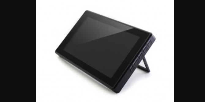
1024×600, 7-inch Capacitive Touch Screen LCD, HDMI interface, supports various systems. Toughened glass capacitive touch panel, 6H hardness. It supports Raspberry Pi and can also be used as a computer monitor.
Features
- 7inch IPS screen, 1024×600 hardware resolution, configurable by software. (up to 1920×1080)
- Toughened glass capacitive touch panel, 6H hardness. (case version only)
- Supports popular mini PC such as Raspberry Pi, BB Black, Banana Pi.
- Used with Raspberry Pi, supports Raspbian, Ubuntu, WIN 10 IoT, driver free.
- Multi-languages OSD menu, for power management, brightness/contrast adjustment, etc.
- It has a 3.5mm audio jack and supports HDMI audio output
- Supports VGA input (specific cable is required and should be purchase separately)
- High-quality PC case, optional tilt angle: 30°/50°
Working with PC
This product supports Windows 10/8.1/8/7 OS.
- Connect the TOUCH interface of LCD to the USB interface of PC. Wait for a while, the windows will automatically recognize the touch function.
- If you use HDMI, you need to connect the HDMI interface of LCD to the HDMI port of PC. About 5s later, you can see the LCD display properly. If you need the audio, you can insert a 3.5mm earphones to HP ports.
- Use VGA, you need to connect the VGA interface of LCD to PC’s VGA ports
by Mini HDMI to VGA Cable.
Note:
- When the computer is connected to several different displays at the same time, only this LCD can be used to control the cursor on the main display, so we recommended to set this LCD as the main display.
- Some of PC cannot support HDMI screen Hot Plug. In this case, restart the PC can solve.
- Sometimes LCD will flicker because of undersupplying from USB cable of PC. You need to connect an external power supply (5V/2A) to DC port.
- HP audio output only works while using HDMI communication
- Mini HDMI to VGA Cable is necessary and need to be purchased separately if you use VGA communication.
Touch Settings on Win 10 PC
Some users want to connect more than one display to their PC. Here we talk about how to setting the touch to make the touchscreen control its screen separately.
- Connect touchscreen to PC. Here we use a standard PC monitor and connect a 7inch HDMI LCD (C) for example. We make the monitor as the main screen and the touchscreen as a secondary screen.
- By default, The touchscreen can only control the cursor on the main screen. Here we set it to control the secondary screen.
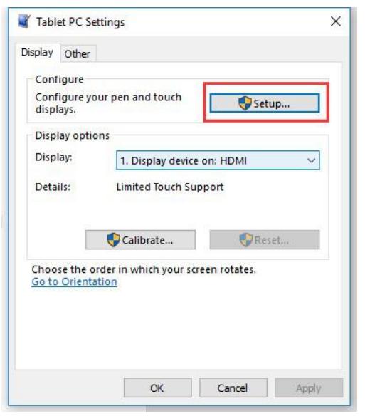
- Open Control Panel and search Tablet PC setting on the control panel and open the tool.

- Click button “Setup…” to set the touchscreen

- After clicking the setup you can find that it is prompt on your first screen with white color background and other screens are white.

- If we want the touch of the touchscreen to control the desktop of the touchscreen itself. Just press Enter key to pass the first screen. And the second screen, when you find that the black text is displayed on the touchscreen, just touch the center of the touchscreen to finish this setting.
- After this setting, the touch on the screen will just control this touchscreen even though it is not the main screen.
Note:
- If the first screen and the second screen are touchscreens as well, you can touch them when the text is displayed on the screens. Then you can find that all the touchscreen can work.
- This method is just tested on win 10 PC.
Working with Raspberry Pi
Supports Raspbian/Ubuntu mate/Windows 10 IoT Core
When working with Raspberry Pi, you should set the resolution of the LCD by yourself, otherwise, the LCD screen will not work. For more detailed information, please read the following section.
Please download the latest version of the image on the Raspberry Pi official website.
- Download the compressed file to the PC, and unzip it to get the .img file.
- Connect the TF card to the PC, use SDFormatter.exe software to format the TF card.
- Open the Win32DiskImager.exe software, select the system image downloaded in step 1, and click`Write’ to write the system image.
- After the image has finished writing, open the config.txt file in the root directory of the TF card, and comment out dtoverlay=vc4-fkms-V3D.
- Add the following code at the end of config.txt, then save and quit the TF card safely.
max_usb_current=1
hdmi_force_hotplug=1
config_hdmi_boost=10
hdmi_group=2
hdmi_mode=87
hdmi_cvt 1024 600 60 6 0 0 0
If you use the LCD with Raspberry Pi 4B, you need to remove line dtoverlay=vc4-fkms-V3D from config.txt file
You must make sure that there are no spaces on either side of the equal sign.
6. Save and connect the TF card to your Pi then power up.7. Connect the Touch interface of LCD to the USB port of Raspberry Pi.8. Connect the HDMI interface of LCD to the HDMI port of Raspberry Pi.
Note:
- Resolution of Ubuntu Mate OS or Windows 10 IoT Core OS can also be set properly by editing config.txt.
- For Pi Zero / Zero W: if you’ve used an SD card on a Pi 3 and then attached the card to the Pi Zero, the touch screen often doesn’t work. In such cases, you have to write a fresh system image to the SD card. The first boot up must be done on the Pi Zero but not Pi 3, due to initialization for a corresponding device.
Rotation(Working with Raspberry Pi)
Display Rotating
Add this statement in the config.txt file (the config file is located in the root directory of the TF card, which is named /boot):
display_rotate=1 #1902: 180 3: 270
Note: For Raspberry Pi 4, you need to comment out dtoverlay=vc4-fkms-V3D.#dtoverlay=vc4-fkms-V3D.
And then restart the Raspberry Pi after saving.
sudo reboot
Touch Rotating
After the display is rotated, the position of touch is incorrect because the touch doesn’t change with the display angle. So the touch also needs to be modified.
- Install libinput.
sudo apt-get install xserver-xorg-input-libinput
If the system you installed is Ubuntu or Jetson Nano. The installation code is:
sudo apt install xserver-xorg-input-synaptics
- Create the xorg.conf.d directory under /etc/X11/ (if the directory already exists, proceeddirectly to step 3).
sudo mkdir /etc/X11/xorg.conf.d
- Copy the 40-libinput-conf file to the directory you created just now.
sudo cp /usr/share/X11/xorg.conf.d/40-libinput.conf /etc/X11/xorg.conf.d/
- Edit this file.
sudo nano /etc/X11/xorg.conf.d/40-libinput.conf
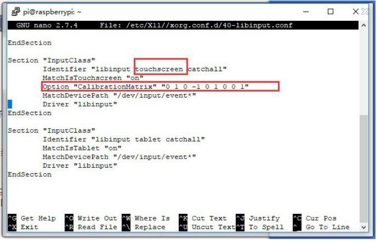
Find the part of the touchscreen, add the following statement inside, and then save the file.
Option "CalibrationMatrix" "0 1 0 -1 0 1 0 0 1"
Similar to the picture below:

- save and reboot your Pi
sudo reboot
After completing these steps. The LCD could rotate 90 degrees both display and touchfunction.
Note:90 degree: Option “CalibrationMatrix” “0 1 0 -1 0 1 0 0 1”180 degree: Option “CalibrationMatrix” “-1 0 1 0 -1 1 0 0 1”
Working with Jetson Nano
To work with Jetson Nano Developer Kit, you don’t need to make software configuration.
- Connect the TOUCH interface of the LCD to the USB interface of Jetson Nano.
- Connect the HDMI interface of the LCD to the HDMI interface of the Jetson Nano and then power on the Jetson Nano. After about 5 seconds, you can see the LCD display normally. If you need to output sound, you can insert a 3.5mm earphones to the HP audio output interface.
Note:
- If the LCD flickers, it may be due to insufficient power supply of the Jetson Nano’s USB interface. It can be solved normally after connecting to an external 5V/2A power supply through the DC interface of the LCD.
- When the HP audio interface is in use, it may be necessary to set the sound output settings in the system.
Working with BeagleBone
How to program Angstrom image file
If this LCD module is used for display only, you can program the latest Angstrom image file to the board directly without any change. The BeagleBone will read the display parameters of the 7 inch HDMI displayer and set the resolution to 1024*600 automatically. When using this LCD module as a touch screen, you should program the image file 7inch HDMI LCD (H) Angstrom Image. The password is re3y. Please follow the steps below to program the image file.
- Download the zip file to your PC, unzip it and get a .img file.
- Connect a TF card to your PC and format your TF card with the SDFormatter.exeNotices: The capability of the TF card which is used here should be more than 4GB. In this operation, a TF card reader is also required, which has to be purchased separately.
- Open the Win32DiskImager.exe software, select the system image downloaded instep 1, and click`Write’ to write the system image.
- After programming the image file, please insert the TF card to your board, pressthe key uBOOT, and hold it till power up. Then, you will enter the system located at the TF card. Wait a moment and you will enter the graphical desktop directly.
Hardware connection
- Connect the LCD to the HDMI on the BeagleBone board with an HDMI to micro HDMI cable (Users need to purchase separately);
- Connect the USB Touch interface on the LCD to the USB interface on the BeagleBone board with a type-A-to-micro USB cable. (BeagleBone has two USB interfaces, one for host and the other for client. In here, you should connect the LCD module to the USB host interface).
How to use with Banana Pi
Before powering up the Banana Pi, you should connect it to a LCD displayer properly, since the Banana Pi may read the resolution parameters of the LCD displayer on startup. And the connection should be remained till the Banana Pi enters the desktop. In this case, even if you disconnect the LCD displayer and reconnect it again to the Banana Pi, the LCD can still work properly.
How to program Raspbian_For_BananaPi image file
Program the image file 7inch HDMI LCD (H) Raspbian Imagewith password 4ph9 to the board. This image file supports the modules BananaPi Pro and BananaPi.
- Download the zip file to your PC, unzip it and get a .img file.
- Connect a TF card to your PC and format your TF card with theSDFormatter.exe
Notices: The capability of TF card which is used here
should be more than 4GB. In this operation, a TF card reader
is also required, which has to be purchased separately.
- Start the Win32DiskImager.exe and select the system image file copied into your PC, then, click the button Write to program the system image file.
Hardware connection
- Connect the LCD to the HDMI on the Banana Pi board with a HDMI cable;
- Connect the USB Touch interface on the LCD to the USB interface on the Banana Pi board with a type-A-to-micro USB cable.
How to load WiFi driver of BananaPi Pro
Comparing with the Banana Pi, the BananaPi Pro has added an on-board WiFi module. When using the BananaPi Pro, you can use SSH to connect to the Pi and execute the following command to load the WiFi driver:
sudo modprobe ap6210
How to use with the Lubuntu system
Program the image file 7inch HDMI LCD (H)Lubuntu Imagewith password u00b to the board. This image file supports the modules BananaPi Pro and BananaPi.
User name: bananapi
Password: bananapi
Keys Introduction
Note: This introduction is based on the 7inch HDMI LCD (H) (with case)

- Power: Open or Close LCD display
- Menu: Open OSD menu (It can also work as “OK button” after entering the menu )
- Up/Left: Direction button
- Down/Right: Direction button
- Exit: it can also work as Return after entering the menu
You can use the “Power” button to close the LCD display for reducing consumption if it will be idle for a long time.
Open the OSD menu by press the “Menu” button, then use the “OK button” and “Direction button” to change the configuration, and finally use “Return button” to exit.
FAQ
Question:
What should I do if I connect to the PC with LCD and it cannot display normally?
Answer:
- Make sure that the HDMI interface of the PC can output normally.
- The PC only connects to this LCD as a monitor without others.
- You should connect the touch cable first and then the HDMI cable.
- Some PC need to be restarted to make the 7 inch HDMI LCD display normally.
Note: The PC must use windows system.
Question:
What is the operating current of 7inch HDMI LCD (H)
Answer:
With 5V power input, it is about 750~850mA
Question:
What is the thickness of the 7inch HDMI LCD (H) screen and PCB board?
Answer:
- The thickness of the screen (LCD + TP) is about 4.5mm;
- The thickness of the PCB board thickness is about 2mm;
- The overall thickness of the screen and PCB board is about 6.88mm;
- The overall thickness of the screen and PCB board (including HDMI interface) is about13.8mm.
Question:
Can 7inch HDMI LCD (H) use an external PWM signal to control the backlight?
Answer:
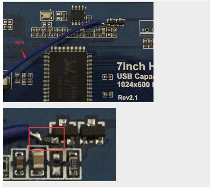
As shown in the figure below: First, connect a 1.2K resistor in series with the pad pins in the figure below (you can choose1K~10K ),fly a wire to the GPIO from the other end of the resistor, and then you can use the GPIO to control the backlight.
[xyz-ips snippet=”download-snippet”]


