E³Point®Gas detection deviceE³Point Remote Gas SensorUser Manual

Symbol Definitions
The following table lists the symbols used in this document to denote certain conditions:
| Symbol | Definition |
 |
ATTENTION: Identifies information that requires special consideration. |
 |
TIP: Identifies advice or hints for the user, often in terms of performing a task. |
 |
REFERENCE _ INTERNAL: Identifies an additional source of information within the booklet. |
| Indicates a situation which, if not avoided, may result in equipment or work (data) on the system being damaged or lost, or may result in the inability to properly operate the process. | |
 |
CAUTION: Indicates a potentially hazardous situation that, if not avoided, may result in minor or moderate injury. It may also be used to alert against unsafe practices.CAUTION: The symbol on the equipment refers the user to the product manual for additional information. The symbol appears next to the required information in the manual. |
 |
WARNING: Indicates a potentially hazardous situation that, if not avoided, can result in serious injury or death.WARNING : symbol on the equipment refers the user to the product manual for additional information. The symbol appears next to the required information in the manual. |
Introduction
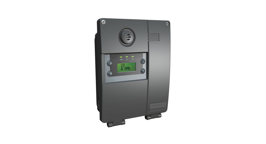
DescriptionThe E³Point Remote Sensor is a toxic or combustible gas detection sensor that is compatible with the E³Point Standalone sensor. The sensor provides continuous monitoring for one of the following gases in ambient air: CO, H2S, O2, NO2, and combustible hazards.The E³Point is designed to be mounted on an extra-wide (2 3/8″) electrical box.The E³Point Remote Sensor is intended for connection to E³Point, Class 2, or limited power source (lps) only.Safety InformationUsers of the E³Point Remote Sensor require a full understanding of the installation, operating, and maintenance instructions, otherwise protection provided by the monitor may be impaired. Read the following warnings before using the monitor.AttentionThis manual must be carefully followed by all individuals who have the responsibility for using or servicing the sensor. Warranties made by Honeywell Analytics with respect to this equipment will be voided if the equipment is not used and serviced in accordance with the instructions in this manual. Additionally, equipment functionality and inherent protection may be compromised if this manual is not carefully followed. If in doubt about a procedure, contact Honeywell Analytics before proceeding.
WarningsWARNING:
- Install according to local electrical regulations and codes.
- Installation should be performed by qualified personnel.
- Do not paint over the sensor screen
- Ensure that the sensor screen is free of dirt and debris.
- Ensure that the sensor screen is not covered.
- Do not expose the monitor to electrical shock and/or continuous mechanical shock.
- Do not expose the sensor to high-pressure water spray.
- Do not use the monitor if it is damaged. Before use, inspect the monitor. Look for cracks and missing metals or plastics. If the monitor is damaged, contactHoneywell Analytics immediately.
- The warranty will be voided if the customer or any unauthorized service personnel attempt to repair the unit.
Installation
Sensor LocationsThe following suggestions should be considered to assure detection of the target gas. Select the most suitable location for each sensor.Air Currents: If there are fans, wind, or other sources of air movement, gases may tend to rise or collect in certain areas of a facility. The local air currents should be assessed to aid in selecting the sensor location. Air convection can often be more important in determining gas concentration areas than factors of Vapor Density.Gas Emission Sources: As a rule, at least one sensor should be located in close proximity to each point where emission is likely to occur.CAUTION: Because each sensor can “report” only what it is detecting at the moment, it is very important that the sensor be located where leaks are most likely to occur.This unit is intended for
- Indoor use
- Maximum altitude 2000 m
- Overvoltage Category II
- Pollution degree 2
- E³Point, Class 2, or limited power source (lps) only
Installation Height
| Detected Gas | Relative Density | Installation Height | |
| (air = 1) | |||
| CO | Carbon monoxide | 0.968 | 1–1.5 m (3–5 ft.) from floor |
| H² S | Hydrogen sulfide | 1.19 | 30 cm (1 ft.) from floor |
| *NO² | Nitrogen dioxide | 1.58 (cold) | 30 cm–1 m (1–3 ft.) from ceiling |
| O² | Oxygen | 1.43 | 1–1.5 m (3–5 ft.) from floor |
| COMB | Most combustibles are heavier than air, with the exception of methane, hydrogen, ethylene, and acetylene. Sensors for gases that are heavier than air should be installed approximately 30 cm (1 ft) from the floor.For combustibles that are lighter than air, sensors should be installed 30 cm (1 ft) from the ceiling, close to the potential leak source. |
* May differ in certain applications. Hot NO 2 from exhaust systems is lighter than ambient air.
WARNING: Some materials such as, but not limited to, tetraethyl lead, silicones, some sulfur, phosphorus, and chlorinated compounds may have a poisoning effect resulting in a loss of sensitivity.
MountingThe E³Point Remote Sensor is designed to be mounted in an extra-wide (2 3/8″) electrical box (not supplied) in the same way as a faceplate. Suggested electrical boxes include T&B BC1110, Hubbell 1110, OZ-Gedney 18112, Appleton 18112, Bowers 10612-BW, or Steel City 68371-12.It does not fit on 4×4″ steel boxes with a single gang mud ring, such as T&B 52CO or 52C13.
- Run the wires through the electrical box and connect to the remote sensor (as indicated in Figure 2).
- Press the sensor (2) into the faceplate (1) and close and press the back cover (3) into the faceplate. You should hear a click.
- Securely mount the unit to the extra-wide electrical box (4) using the appropriate screws (5).

Figure 1. E³Point Remote Sensor Parts
Wiring Diagram
Connecting the Main Sensor to the Remote

Figure 2. Connecting Main Sensor to Remote
The OUT1 and OUT2 connectors on the remote sensor’s terminal are not used. DO NOT connect any wires to these locations.
Wire: Signal wiring should be done with #20-24 AWG shielded twisted pair cable Belden 9841 or similar. Network units should have no more than 2,000 ft (600 m) of #22 AWG wire. Smaller gauge sizes are limited by the same resistance limit. The LED on the faceplate blinks to indicate communication with the main unit.
Specifications
| Power:(must be E³Point, Class 2, or limited power source [lps]) | Electrochemical sensor: 10-24 VDC, 50 mA |
| Catalytic: 10-16 VDC, 100 mA | |
| Operating temperature: | 20ºC to 50ºC (-4ºF to 122ºF) |
| Operating humidity: | 15 to 90% relative humidity (non-condensing) |
| Sensor type: | The electrochemical cell (CO, NO2, H2S, O2); catalytic(Comb) |
| Visual indicator: | Amber LED (Tx) |
| Size (DxWxH): | 3.5 x 4.5 x 6.5 cm (1.36 x 1.75 x 2.56 in.) |
| Weight: | 38 g (1.34 oz.) |
Detection Ranges and Alarm Levels
| Gas Detected | Range | Alarm A | Alarm B | Alarm C | Maximum
Overrange |
|
| CO | Carbon monoxide | 0-250 ppm | 25 ppm | 200 ppm | 225 ppm | 500 ppm |
| H2S | Hydrogen sulfide | 0-50 ppm | 10 ppm | 15 ppm | 45 ppm | 150 ppm |
| NO2 | Nitrogen dioxide | 0-10 ppm | 0.7 ppm | 2 ppm | 5 ppm | 1000 ppm |
| 02 | Oxygen | 0-25 %vol | 19.5 %vol. | 22 %vol. | 23 %vol | 100 %vol |
| COMB | Combustibles | 0-100 %LEL | 25 %LEL | 50 %LEL | 90 %LEL | 100 %LEL |
Maximum over the range is the cell exposure to the gas concentration that may result in permanent damage to the cell.
Sensor OverrangeWhen Interfacing with the E³Point Main Unit
- Sensor over range occurs whenever the gas concentration reading is higher than the full-scale value, no matter how high the gas concentration is.
- Overrange Warning state is latched when true. It stays activated indefinitely and is independent of gas concentration reading.
- Refer to the E³Point Network or Standalone manual for a description of over range conditions.
Standard Parts List
Figure 3. E³Point Remote Sensor Parts
| item # | Description |
| 1 | E3Point Remote Sensor faceplate |
| 2 | E3Point sensor |
| 3 | Remote sensor back cover |
| 4 | Extra-wide rectangular J-box (not included) |
| 5 | Mounting screw (not included) |
To change a sensor cartridge, disconnect all power to the device, remove the back cover, pull out the “smart sensor” cartridge, and press the replacement cartridge into place. Once the Smart Sensor is firmly in place, replace the back cover and reconnect power.Use caution when pressing the Smart Sensor into place to avoid bending the pins.
Periodic Inspection and MaintenanceThis unit requires regular inspection.n. The frequency will be determined by the operating conditions, which includes extreme temperatures, exposure to contaminants, or gas. Inspect the unit and perform a gas test at least once every 6 months.Contact a Honeywell Sales or Service representative for information about maintenance. Calibration kits with instructions are available from Honeywell.Maintenance
- The unit will provide years of service with minimal care.
- Visually inspect at regular intervals to ensure optimum operating condition (no breakage, sensor filter not blocked or clogged, etc.)
- An accurate log of all maintenance, calibration, and occurrence must be kept for the proper service of this product.
- Do not expose the sensor to high-pressure water spray. Sensors should not be exposed to solvents.
- Clean the exterior with a soft, damp cloth. Do not use solvents soaps, or polishes.
- Do not immerse the unit in liquids.
Sensor Life SpanSensor life span may be affected by certain operating conditions or by exposure to concentrations higher than the detection range.
| Sensor Type | Life Span Specification (typical) |
| CO | 6 years, normal use at temperatures >-10°C |
| H2S | 3 years, in air |
| NO2 | 3 years, in air |
| 02 | 3 years until readings are 85% of original 20.9% input |
| COMB | 3 years. in air |
Limited WarrantyHoneywell Analytics Inc. warrants to the original purchaser and/or ultimate customer (“Purchaser”) of Honeywell products (“Product”) that if any part thereof proves to be defective in material or workmanship within one (1) year, such defective part will be repaired or replaced, free of charge, at Honeywell Analytics’ discretion if shipped prepaid to Honeywell Analytics at 4005 Matte Blvd., Suite G, Brossard, Quebec, Canada, J4Y 2P4, in a package equal to or in the original container. The Product will be returned freight prepaid and repaired or replaced if it is determined by Honeywell Analytics that the part failed due to defective materials or workmanship. The repair or replacement of any such defective part shall be Honeywell Analytics’ sole and exclusive responsibility and liability under this limited warranty.Re-Stocking PolicyThe following re-stocking fees will apply when customers return products for credit:A 15% re-stocking fee will be applied if the product is returned within 1 month following the shipping date.A 30% re-stocking fee will be applied if the product is returned within 3 months following the shipping date.A full credit (less re-stocking fee) will be issued only if the product is in perfect working condition. If repairs are required on the returned product, the cost of these repairs will be deducted from the credit to be issued.No credits will be issued beyond the three-month period.ExclusionsIf gas sensors are part of the Product, the gas sensor is covered by a twelve (12) month limited warranty of the manufacturer.
Disclaimer of Unstated WarrantiesIf gas sensors are covered by this limited warranty, the gas sensor is subject to inspection by Honeywell Analytics for extended exposure to excessive gas concentrations if a claim by the Purchaser is made under this limited warranty. Should such inspection indicate that the gas sensor has been expended rather than failed prematurely, this limited warranty shall not apply to the Product.This limited warranty does not cover consumable items, such as batteries, or items subject to wear or periodic replacement, including lamps, fuses, valves, vanes, sensor elements, cartridges, or filter elements.Warranty Limitation and ExclusionHoneywell Analytics will have no further obligation under this limited warranty. All warranty obligations of Honeywell Analytics are void if the Product has been subject to abuse, misuse, negligence, or accident or if the Purchaser fails to perform any of the duties set forth in this limited warranty or if the Product has not been operated in accordance with instructions, or if the Product serial number has been removed or altered.Disclaimer of Unstated WarrantiesThe warranty printed above is the only warranty applicable to this purchase. All other warranties, express or implied, including, but not limited to, the implied warranties of merchantability or fitness for a particular purpose are hereby disclaimed.
Limitation of LiabilityIt is understood and agreed that Honeywell Analytics’ liability, whether in contract, in tort, under any warranty, in negligence, or otherwise shall not exceed the amount of the purchase price paid by the purchaser for the product, and under no circumstances shall Honeywell Analytics be liable for special, indirect, or consequential damages. The price stated for the product is a consideration limiting Honeywell Analytics’ liability. No action, regardless of form, arising out of the transactions under this warranty may be brought by the purchaser more than one year after the cause of actions has occurred.
![]()
| Find out more/ Pour renseignementswww.honeywellanalytics.com | ContactHoneywell Analytics Inc.4005 Matte, Suite GBrossard, QuebecCanada, H4Y 2P41-800-563-2967www.honeywellanalytics.com | Technical Services/ ServicesTechniques[email protected] |
1998M0773revision 4©2013 Honeywell Analytics
References
[xyz-ips snippet=”download-snippet”]