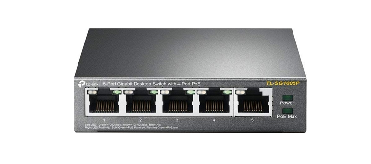

Installation Guide5-Port Gigabit Desktop PoE Switch
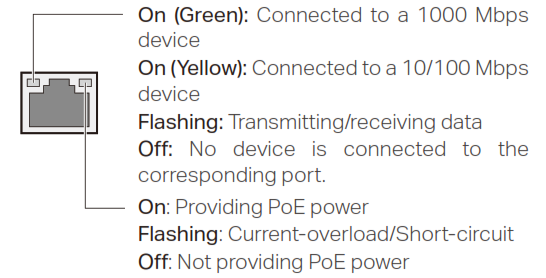
LED Explanation
PowerOn: Power onOff: Power off![]() Power
Power
Link/Act and PoE Status
PoE MAX![]() PoE MaxTL-SG1005LPOn: 33 W ≤ Total power supply < 40 WFlashing: Total power supply ≥ 40 WOff: Total power supply < 33 W
PoE MaxTL-SG1005LPOn: 33 W ≤ Total power supply < 40 WFlashing: Total power supply ≥ 40 WOff: Total power supply < 33 W
TL-SG1005POn: 58 W ≤ Total power supply < 65 WFlashing: Total power supply ≥ 65 WOff: Total power supply < 58W
Note: For simplicity, we will take TL-SG1005P for example throughout this Guide.
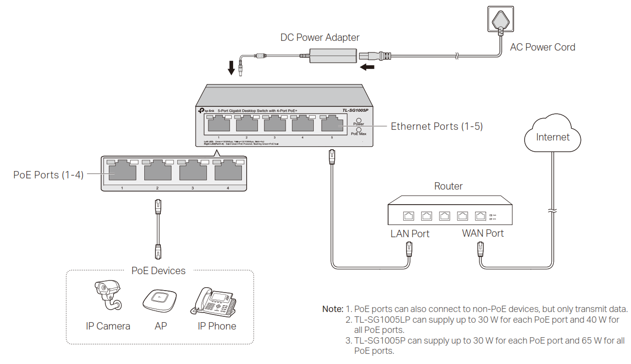
Connection
Specifications
General Specifications
| Standard | IEEE802.3i, IEEE802.3u, IEEE802.3ab, IEEE802.3x, IEEE802.3af, IEEE802.3at, IEEE802.1p |
| Protocol | CSMA/CD |
| Interface | 5 10/100/1000 Mbps RJ45 Ports Auto-Negotiation MDI/MDIX PoE Ports: Port 1-Port 4, Total Power Supply: 40 W (TL-SG1005LP)/65 W (TL-SG1005P) |
| Network Media (Cable) | 10BASE-T: UTP category 3, 4, 5 cable (maximum 100 m);EIA/TIA-568 100Ω STP (maximum 100 m)100BASE-TX: UTP category 5, 5e cable (maximum 100 m); EIA/TIA-568 100Ω STP (maximum 100 m)1000BASE-T: UTP category 5e cable or above (maximum 100 m); EIA/TIA-568 100Ω STP (maximum 100 m) |
| Switching Capacity | 10 Gbps |
| MAC Address Table | 2 K |
| Transfer Method | Store-and-Forward |
| MAC Address Learning | Automatically learning, automatically aging |
| Power Supply | External Power AdapterInput: 100-240 VAC, 50/60 HzOutput: 53.5 VDC /0.81 A (TL-SG1005LP) 53.5 VDC /1.31 A (TL-SG1005P) |
| Wall Mountable | Yes |
| Distance Between Mounting Holes | 52 mm |
Environmental and Physical Specifications
| Operating Temperature | 0 ˚C to 40 ˚C (32 ˚F to 104 ˚F) |
| Storage Temperature | -40 ˚C to 70 ˚C (-40 ˚F to 158 ˚F) |
| Operating Humidity | 10% to 90%RH non-condensing |
| Storage Humidity | 5% to 90%RH non-condensing |
PoE DisclaimerPoE budget calculations are based on laboratory testing. Actual PoE power budget is not guaranteed and will vary as a result of client limitations and environmental factors.
EU Declaration of ConformityTP-Link hereby declares that the device is in compliance with the essential requirements and other relevant provisions of directives 2014/30/EU, 2014/35/EU, 2009/125/EC, 2011/65/EU and (EU)2015/863.The original EU declaration of conformity may be found at https://www.tp-link.com/en/ce.
Frequently Asked Questions (FAQ)
Q1. Why is the Power LED not lit?The Power LED should be lit when the power system is working normally. If the Power LED is not lit, please try the following:A1: Make sure the AC power cord is connected to the switch with power source properly.A2: Make sure the voltage of the power supply meets the requirements of the input voltage of the switch.A3: Make sure the power source is on.
Q2. Why is the Link/Act LED not lit while a device is connected to the corresponding port?Please try the following:A1: Make sure that the cable connectors are firmly plugged into the switch and the device.A2: Make sure the connected device is turned on and works normally.A3: The cable must be less than 100 meters long (328 feet).
Q3. Why are PoE ports not supplying power for PoE devices?When the total power consumption of connected PoE devices exceeds the maximum, the PoE port with a smaller port number has higher priority. The system will cut off power to the ports with larger port numbers to ensure supplying to other ports.Take TL-SG1005P as an example. If port 1, 2 and 4 are consuming 15.4 W respectively, and an additional PoE device with 19 W is inserted to port 3, the system will cut off the power of port 4 to compensate for the overload.
![]() To ask questions, find answers, and communicate with TP-Link users or engineers, please visit https://community.tp-link.com to join TP-Link Community.
To ask questions, find answers, and communicate with TP-Link users or engineers, please visit https://community.tp-link.com to join TP-Link Community.![]() For technical support and other information, please visit https://www.tp-link.com/support, or simply scan the QR code
For technical support and other information, please visit https://www.tp-link.com/support, or simply scan the QR code![]() If you have any suggestions or needs on the product guides, welcome to email [email protected].
If you have any suggestions or needs on the product guides, welcome to email [email protected].
 http://www.tp-link.com/support
Safety Information
- Keep the device away from water, fire, humidity or hot environments.
- Do not attempt to disassemble, repair, or modify the device.
- Do not use damaged charger or USB cable to charge the device.
- Do not use any other chargers than those recommended.
- Adapter shall be installed near the equipment and shall be easily accessible.
- Place the device with its bottom surface downward.
- Use only power supplies which are provided by the manufacturer and in the origin packing of this product. If you have any questions, please don’t hesitate to contact us.
FCC compliance information statement
Product Name: Gigabit Desktop SwitchModel Number: TL-SG1005LP/TL-SG1005P
|
Component Name |
Model |
| I.T.E. POWER SUPPLY | T535081-2-DT (For TL-SG1005LP)
T535131-2-DT (For TL-SG1005P) |
Responsible party:TP-Link USA Corporation, d/b/a TP-Link North America, Inc.Address: 145 South State College Blvd. Suite 400, Brea, CA 92821Website: https://www.tp-link.com/us/Tel: +1 626 333 0234Fax: +1 909 527 6803E-mail: [email protected]This equipment has been tested and found to comply with the limits for a Class A digital device, pursuant to part 15 of the FCC Rules. These limits are designed to provide reasonable protection against harmful interference when the equipment is operated in a commercial environment. This equipment generates, uses, and can radiate radio frequency energy and, if not installed and used in accordance with the instruction manual, may cause harmful interference to radio communications. Operation of this equipment in a residential area is likely to cause harmful interference in which case the user will be required to correct the interference at his own expense.• Reorient or relocate the receiving antenna. This device complies with part 15 of the FCC Rules. Operation is subject to the following two conditions:1) This device may not cause harmful interference.2) This device must accept any interference received, including interference that may cause undesired operation.Any changes or modifications not expressly approved by the party responsible for compliance could void the user’s authority to operate the equipment.We, TP-Link USA Corporation, has determined that the equipment shown as above has been shown to comply with the applicable technical standards, FCC part 15. There is no unauthorized change is made in the equipment and the equipment is properly maintained and operated.Issue Date: 2020.2.24
CE Mark WarningThis is a class A product. In a domestic environment, this product may cause radio interference, in which case the user may be required to take adequate measures.
FCC compliance information statement![]() Product Name: I.T.E. POWER SUPPLYModel Number: T535081-2-DT/T535131-2-DTResponsible party:TP-Link USA Corporation, d/b/a TP-Link North America, Inc.Address: 145 South State College Blvd. Suite 400, Brea, CA 92821Website: https://www.tp-link.com/us/Tel: +1 626 333 0234Fax: +1 909 527 6803E-mail: [email protected]This equipment has been tested and found to comply with the limits for a Class A digital device, pursuant to part 15 of the FCC Rules. These limits are designed to provide reasonable protection against harmful interference when the equipment is operated in a commercial environment. This equipment generates, uses, and can radiate radio frequency energy and, if not installed and used in accordance with the instruction manual, may cause harmful interference to radio communications. Operation of this equipment in a residential area is likely to cause harmful interference in which case the user will be required to correct the interference at his own expense. This device complies with part 15 of the FCC Rules. Operation is subject to the following two conditions:1) This device may not cause harmful interference.2) This device must accept any interference received, including interference that may cause undesired operation.Any changes or modifications not expressly approved by the party responsible for compliance could void the user’s authority to operate the equipment.We, TP-Link USA Corporation, has determined that the equipment shown as above has been shown to comply with the applicable technical standards, FCC part 15. There is no unauthorized change is made in the equipment and the equipment is properly maintained and operated.Issue Date: 2020.2.24
Product Name: I.T.E. POWER SUPPLYModel Number: T535081-2-DT/T535131-2-DTResponsible party:TP-Link USA Corporation, d/b/a TP-Link North America, Inc.Address: 145 South State College Blvd. Suite 400, Brea, CA 92821Website: https://www.tp-link.com/us/Tel: +1 626 333 0234Fax: +1 909 527 6803E-mail: [email protected]This equipment has been tested and found to comply with the limits for a Class A digital device, pursuant to part 15 of the FCC Rules. These limits are designed to provide reasonable protection against harmful interference when the equipment is operated in a commercial environment. This equipment generates, uses, and can radiate radio frequency energy and, if not installed and used in accordance with the instruction manual, may cause harmful interference to radio communications. Operation of this equipment in a residential area is likely to cause harmful interference in which case the user will be required to correct the interference at his own expense. This device complies with part 15 of the FCC Rules. Operation is subject to the following two conditions:1) This device may not cause harmful interference.2) This device must accept any interference received, including interference that may cause undesired operation.Any changes or modifications not expressly approved by the party responsible for compliance could void the user’s authority to operate the equipment.We, TP-Link USA Corporation, has determined that the equipment shown as above has been shown to comply with the applicable technical standards, FCC part 15. There is no unauthorized change is made in the equipment and the equipment is properly maintained and operated.Issue Date: 2020.2.24
Mounting Requirements
To mount the device on a wall, use 2 screws that comply with ANSI B1.1 4#, (5#), 6#, 8# standard and are more than 8.5 mm in length. When the screws are fixed on the wall, the distance between the screw head and the wall should be more than 1.5 mm.
| Standard | Diameter |
| ANSI B1.1 #4 | 2.845 mm |
| ANSI B1.1 #5 | 3.175 mm |
| ANSI B1.1 #6 | 3.505 mm |
| ANSI B1.1 #8 | 4.166 mm |
Industry Canada StatementCAN ICES-3 (A)/NMB-3(A)Explanation of the symbols on the product label
| DC voltage | |
| Indoor use only | |
 |
RECYCLINGThis product bears the selective sorting symbol for Waste electrical and electronic equipment (WEEE). This means that this product must be handled pursuant to European directive 2012/19/EU in order to be recycled or dismantled to minimize its impact on the environment. User has the choice to give his product to a competent recycling organization or to the retailer when he buys a new electrical or electronic equipment. |
| Polarity of output terminals | |
| Energy efficiency Marking (Level VI) |
References
域名售卖
TP-Link Product Support – Wireless Networking Equipment Support
link.com is available for purchase – Sedo.com
CE Regulatory Compliance | TP-Link
TP-Link Community
WiFi Networking Equipment for Home & Business | TP-Link
TP-Link Community
域名售卖
CE Regulatory Compliance | TP-Link
TP-Link Product Support – Wireless Networking Equipment Support
Regulatory Compliance | TP-Link
TP-Link Product Support – Wireless Networking Equipment Support
TP-Link Community
CE Regulatory Compliance | TP-Link
域名售卖
[xyz-ips snippet=”download-snippet”]