
TP-Link AC Power Supply Module Installation Guide
7106508813 REV2.1.0© 2020 TP-Link
Introduction
Overview of the Product
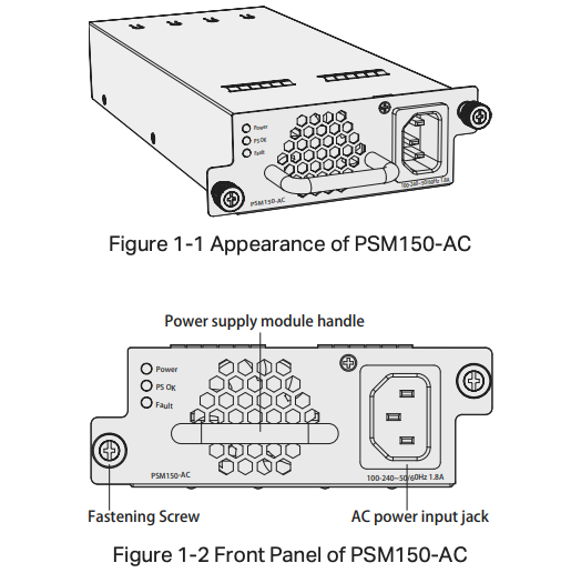
The PSM150-AC is an AC-input and DC-output power supply module. It can convert the input voltage to 12 Volts with the maximum output power of 75 Watts. The power supply module is fully hot swappable, helping to ensure no system interruption during installation or replacement. PSM150-AC is applicable to multiple TP-Link switch models.
Description of LEDs
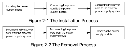
There are three LEDs on the front panel of PSM150-AC.
| LED Status | Description |
| Power On | Power supply module is powered on and running well, but not supplying power to the switch. |
| PS OK OffFault Off | |
| Power OnPS OK On | Power supply module is powered on and running well, and supplying power to the switch. |
| Fault Off | |
| Power OnFault On | The circuit has faults, such as output over-voltage, output under-voltage, output over-current, output short circuit, hot-swap control failure (note 1) or fan fault. |
| PS OK Off | |
| Power OffPS OK OffFault Off | AC power off or power supply fault. |
Table 1-1 LED Status
Note:
- Hot-swap control function will be checked when PSM150-AC is powered on but has not been inserted into the switch. If the Fault LED is on under this condition, please do not insert PSM150-AC into the switch, otherwise the power supply module or the powered devices may be damaged.
- The failure of output over-voltage or over-current may cause the power LED to flash.
Description of Features
| Feature | Description |
| Protection function | Includes output over-voltage protection, output under-voltage protection, output short circuit protection and output over-current protection. |
| Redundant backup | Supports dual power modules combining in parallel to implement 1+1 redundancy for uninterruptible power supply. |
| Hot Swappable | In the case of 1+1 redundant power supply system, the PSM150-AC can be plugged out or plugged in without shutting down the switch. |
Table 1-2 Features of PSM150-AC
When the power module reverts to the protected state, its recovery characteristics are shown in Table 1-3.
| Protection function | Protective action | Recovery characteristics |
| Output over-voltage & under-voltage protection | Power supply module locked and cut-off supply | The power supply can not recover automatically |
| Output short circuit protection | Power supply module locked and cut-off supply | Power supply module reverts into the auto-retry mode. It can recover automatically when the fault is cleared. |
| Output over-current protection | Power supply module locked and cut-off supply | Power supply module reverts into the auto-retry mode. It can recover automatically when the fault is cleared. |
Table 1-3 Protection Functions of PSM150-AC
Note: When the power supply module is locked or auto-retry continually, you can try the following steps to restore the device.
- Disconnect the power cord from the external power supply system.
- Disconnect the power cord from the power supply module.
- Remove the power supply module from the switch.
- Insert the power supply module again.
- Connect the power cord to the power supply module again.
- Connect the other end of the power cord to the external supply system.
Installation
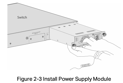
The process of installation and removal of the power supply module is illustrated in Figure 2-1 and Figure 2-2.
Note: For safety considerations, the above process are recommended by TP-Link, however, PSM150-AC can also support installation or removal when the AC power supply is on.
Safety Information
To avoid damage to the power supply module and the equipment and bodily injury, please observe the following notes:
- When you install and remove the power supply module, please wear an ESD-preventive wrist strap, and make sure that it has good skin contact and is well grounded.
- Before installing the power supply module, make sure that the voltage of external power supply system is the same with the voltage marked in the power supply module, and the output voltage of the power supply module is the same with the required voltage of the powered devices in order to prevent damaging the power supply module or the powered devices.
- Do not touch any exposed wires or terminals to avoid bodily injury.
- Do not place the power module in a humid place or let the liquid into the power supply module.
- If there is a failure inside the module, please contact service personnel, instead of opening the housing of the module.
Tools for Installation
- Straight screwdriver
- Philips screwdriver
- ESD-preventive wrist strap
Installing & Removing the Power Supply Module
- Installing the Power Supply Module
- Wear an ESD-preventive wrist strap, and make sure that it has good skin contact and is well grounded.
- Grip the handle of the module with one hand, and hold the bottom of the module using your other hand. Gently push the module in along the slot guide rail until the module is flush with the switch, as shown in Figure 2-3.

- Tighten the captive screws with a Phillips screwdriver to fix the power supply module in place.
- Removing the Power Supply Module
- Wear an ESD-preventive wrist strap, and make sure that it has good skin contact and is well grounded.
- Remove the power cord from the external power supply system and the power module.
- Use a Phillips screwdriver to loosen the captive screws at both sides of the power supply module until all spring pressure is released.
- Pull the handle with one hand towards you along the guide rails, and hold the bottom of the module using your other hand, until it completely comes out of the switch chassis.
Note:
When installing or removing a power supply module, pay attention to the following points:
- Make sure that the power supply module is set correctly in the operation of installation.
- Do not use too much force in the installation. If resistance is encountered or positions of the power supply module appear larger during installation, you must first remove the module and then reinstall the module.
- If screws cannot be tighten, it may be due to the power supply module is not installed properly. Please check carefully.
- In order to better protect the power supply module during removal, it is recommended that you package it in an antistatic bag.
Connecting the Power Cord
- Connecting the Power Cord
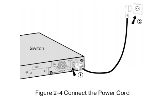
After the power supply module is installed on the switch, please plug the female connector of the provided power cord into the power socket of the device, and the male connector into a power outlet as the following figure shows.
Verifying the Installation
To verify the installation status of PSM150-AC, firstly, please make sure the two captive screws on PSM150-AC are tightened, then connect the power cord and check the LEDs of PSM150-AC. If the Power LED is on while Fault LED is off, it indicates that the AC power input is good and the device is working properly, and the installation of PSM150-AC has been successful.
Appendix: Specifications
| Item | Specification |
| AC Power Input | 100 V–240 V ~ 50/60 Hz |
| Output Voltage | 12 VDC |
| Output Current | 6.25 A (Maximum) |
| Output Power | 75 W (Maximum) |
| Temperature | Operation : 0°C to 40°C (32 to 104°F) |
| Storage: -40°C to 70°C (-40 to 158°F) | |
| Humidity | Operation : 20% to 90% RH Non-condensing |
| Storage: 10% to 95% RH Non-condensing |
Safety Information
- Keep the device away from water, fire, humidity or hot environments.
- Do not attempt to disassemble, repair, or modify the device. If you need service, please contact us.
- Avoid using this product during an electrical storm. There may be a remote risk of electric shock from lightning.
EU Declaration of Conformity
TP-Link hereby declares that the device is in compliance with the essential requirements and other relevant provisions of directives 2014/30/EU, 2014/35/EU, 2009/125/EC, 2011/65/EU and (EU)2015/863.
The original EU declaration of conformity may be found at https://www.tp-link.com/en/ce.
![]()
Industry Canada Statement
CAN ICES-3 (A)/NMB-3(A)
![]() FCC compliance information statement
FCC compliance information statement
Product Name: AC Power Supply Module
Model Number: PSM150-AC
Responsible party: TP-Link USA Corporation, d/b/a TP-Link North America, Inc.
Address: 145 South State College Blvd. Suite 400, Brea, CA 92821
Website: https://www.tp-link.com/us/
Tel: +1 626 333 0234
Fax: +1 909 527 6803
E-mail: [email protected]
This equipment has been tested and found to comply with the limits for a Class A digital device, pursuant to part 15 of the FCC Rules. These limits are designed to provide reasonable protection against harmful interference when the equipment is operated in a commercial environment. This equipment generates, uses, and can radiate radio frequency energy and, if not installed and used in accordance with the instruction manual, may cause harmful interference to radio communications. Operation of this equipment in a residential area is likely to cause harmful interference in which case the user will be required to correct the interference at his own expense.
We, TP-Link USA Corporation, has determined that the equipment shown as above has been shown to comply with the applicable technical standards, FCC part 15. There is no unauthorized change is made in the equipment and the equipment is properly maintained and operated.
Issue Date: 2020/04/29
This device complies with part 15 of the FCC Rules. Operation is subject to the following two conditions: 1) This device may not cause harmful interference. 2) This device must accept any interference received, including interference that may cause undesired operation. Any changes or modifications not expressly approved by the party responsible for compliance could void the user’s authority to operate the equipment.
![]() CE Mark Warning
CE Mark Warning
This is a class A product. In a domestic environment, this product may cause radio interference, in which case the user may be required to take adequate measures.
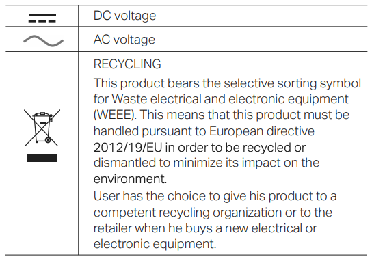
Explanation of the symbols on the product label
![]() To ask questions, find answers, and communicate with TP-Link users or engineers, please visit https://community.tp-link.com to join TP-Link Community.
To ask questions, find answers, and communicate with TP-Link users or engineers, please visit https://community.tp-link.com to join TP-Link Community.
![]()
 For technical support and other information, please visit https://www.tp-link.com/support, or simply scan the QR code.
![]() If you have any suggestions or needs on the product guides, welcome to email [email protected].
If you have any suggestions or needs on the product guides, welcome to email [email protected].
References
[xyz-ips snippet=”download-snippet”]