tp-link Outdoor CPE

Overview
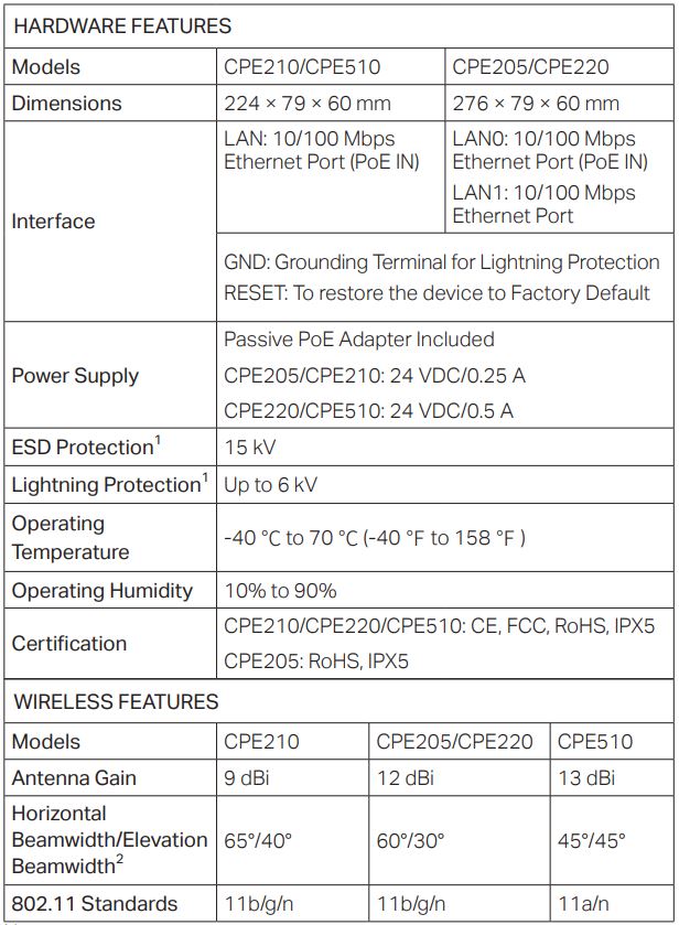
TP-Link’s Pharos series outdoor CPEs are dedicated to outdoor wireless network solutions. This guide is applicable to products including CPE205, CPE210, CPE220, and CPE510.
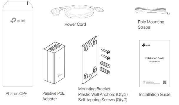
- Package Contents
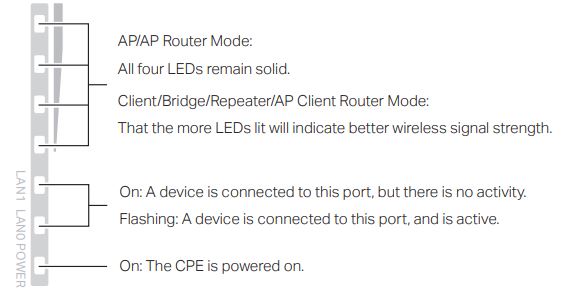
- LED Explanation

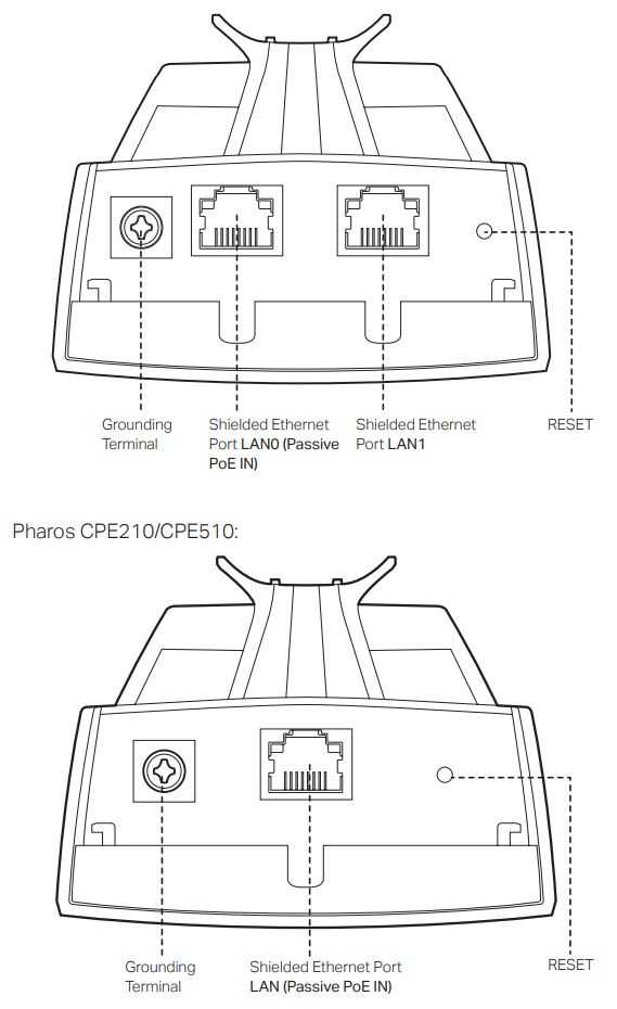
- Panel LayoutPharos CPE205/CPE220:
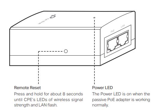
Passive PoE Adapter:
Hardware Connection
1. Site Consideration
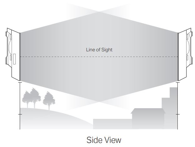
- Mounting HeightEnsure a clear line of sight between the wireless devices for optimum performance. An elevated location is recommended as obstacles like trees, buildings and large steel structures will weaken the wireless signal. See ‘Q2’ in ‘FAQ’ for details about how to calculate the minimum mounting height of the devices.
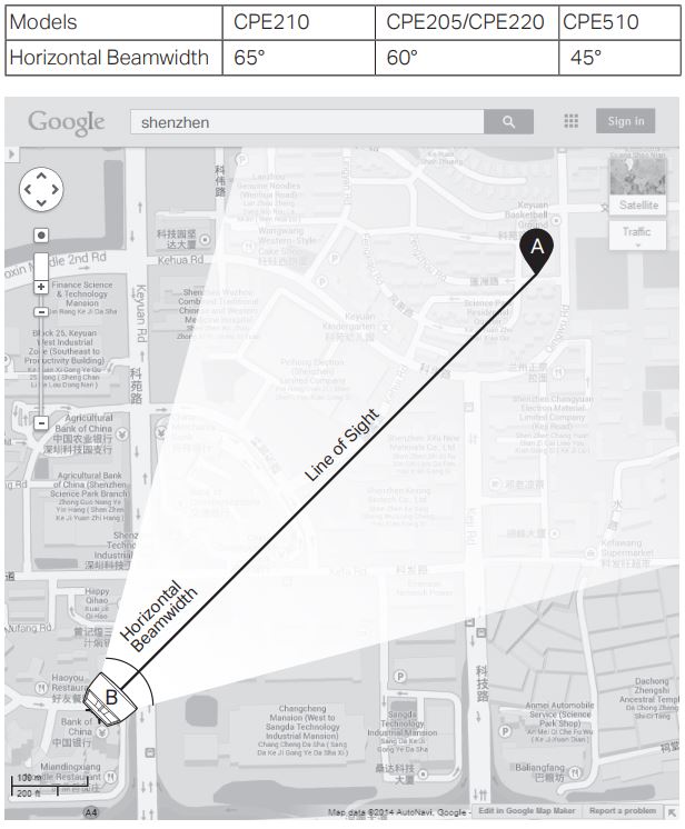
- OrientationInstall the CPE devices with the front-facing of the intended signal receiving devices. You can orient the devices with the assistance of Google Maps, GPS, and some landmarks according to the horizontal beamwidth listed below.
2. Connection and Installation
Connect and mount the CPE and power adapter as shown below. The following introduction takes CPE220 as an example.
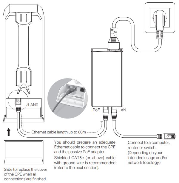
- Connecting CPE and Power AdapterConnect the CPE and power adapter as shown in the figure below.
- Mounting CPE
At the selected site, approximately align the CPE to the direction that you have oriented.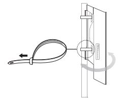
- Mounting Power Adapter (Optional)
Follow the steps below to mount the power adapter:![]() To ensure the passive PoE adapter is attached most securely, it is recommended to install the adapter with the Ethernet port facing upward.
To ensure the passive PoE adapter is attached most securely, it is recommended to install the adapter with the Ethernet port facing upward.
1. Drill two holes on the wall and insert the plastic wall anchors into the holes. Secure the mounting bracket to the wall. Make sure the shoulders at the corners of the mounting bracket are on the outside and pointing upward.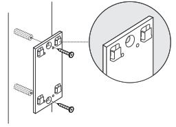 2. Attach the passive PoE adapter to the mounting bracket by sliding the adapter in the direction of the arrows until it locks into place.
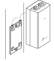
3. Lightning & ESD Protection
Proper grounding is extremely important for outdoor devices. By using a shielded CAT5e (or above) cable with a ground wire for the connection and the provided PoE adapter (method 1 ), you can effectively eliminate ESD attacks. If you use the general CAT5e cable for the connection, then it is necessary to connect the grounding terminal of the CPE to the earth ground through grounding cable (method 2 ). The following introduction takes CPE220 as an example.

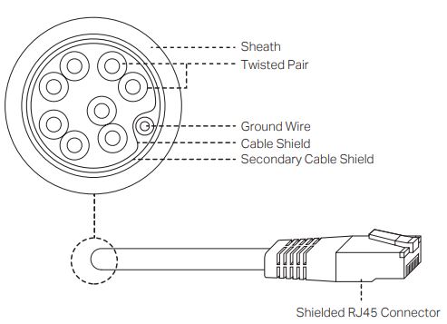 Shielded CAT5e (or above) Cable with Ground Wire
Software Configuration
This chapter introduces the login to the PharOS Web Interface and the software configurations.
1. Logging in to the PharOS
1. Before accessing the PharOS Web Interface, you need to assign a static IP address 192.168.0.X (X ranges between 2 and 253, e.g. 192.168.0.10) to your computer.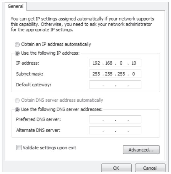 2. Open a web browser, type http://192.168.0.254 into the address field, and press Enter (Windows) or Return (Mac). It is recommended to use the latest version of Google Chrome, Firefox, or Safari.
 ![]()
3. Enter admin for both User Name and Password. Read and agree on the terms of use, then click Login.4. Change the default User Name and Password to protect your CPE. Let’s start configuring the CPE.![]() For subsequent logins, use the new username and password.
For subsequent logins, use the new username and password.
For more configurations, please visit https://www.tp-link.com/support to download the User Guide of Pharos products in the download center.
2. Typical Application Configuration
The typical topology is as follows. A wireless bridge is built between two locations that are far from each other. Follow the instructions below to configure the Access Point and Client.

Configure the Access Point (AP)1. Log in to PharOS and go to the Quick Setup page.2. Operation Mode: Select Access Point and click Next.3. LAN Settings: Click Next.4. Wireless AP Settings:a. Create a new SSID (Network name) for your wireless network.b. Select WPA-PSK/WPA2-PSK for the Security method and create a PSK Password to protect your AP.c. Enter the distance between the Access Point and the Client into the Distance Setting field.d. Select the MAXtream checkbox (Refer to Q3 in FAQ for details about MAXtream), and click Next.5. Finish: Verify your settings and click Finish to complete the configuration.
Configure the Client
- Log in to PharOS and go to the Quick Setup page.
- Operation Mode: Select Client and click Next.
- LAN Settings: Change the IP Address to 192.168.0.X (X ranges between 2 and 253), the same subnet with the Access Point, and click Next.
- Wireless Client Settings:a. Click Survey and select the SSID of the Access Point in the AP list, then click Connect.b. Select WPA-PSK/WPA2-PSK from the Security option, enter the same PSK password and distance value of the Access Point, then click Next.
- Finish: Verify your settings and click Finish to complete the configuration.
For more configurations, please visit https://www.tp-link.com/support to download the User Guide of Pharos products in the download center.
Antenna Alignment
Antenna alignment can help you to optimize the antenna signal. To get the best wireless performance, click Antenna Alignment from the drop-down list on the upper-right corner and enable Alignment Beep during alignment. Then adjust your antenna until the sound frequency turns to the lowest.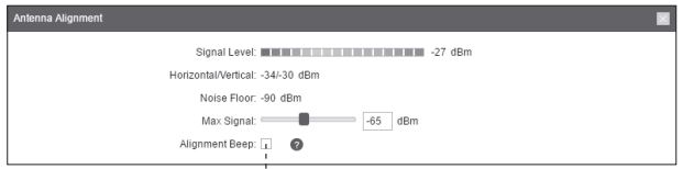 Check the box to enable the beep sound. Its frequency can help you to estimate the signal strength received by the antenna. The lower the sound frequency, the stronger the signal strength.
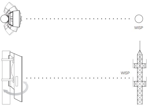
Specifications
Note:1. Estimation is based on copper grounding cable and shielded CAT5e cable with ground wire.2. Beamwidth values may vary throughout the operating frequency.
FAQ
Q1. How to restore the CPE to its factory default settings?With the CPE powered on, you can reset the CPE via either the RESET button on the CPE or the Remote Reset button on the Passive PoE Adapter.Method 1: Via the RESET Button on the CPEThe following picture takes CPE220 as an example.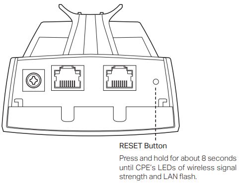 Method 2: Via the Remote Reset Button on the Passive PoE Adapter
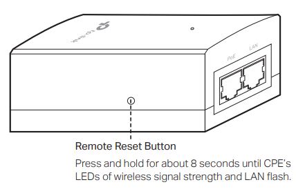
Q2. How to calculate the minimum mounting height of the devices?In order to maximize the received signal strength of the devices, installers need to minimize the effect of the out-of-phase signals, which are caused by obstacles in the path between the transmitter and the receiver. Fresnel Zone is a usual method to calculate this path, as shown in the formula and the figure below.
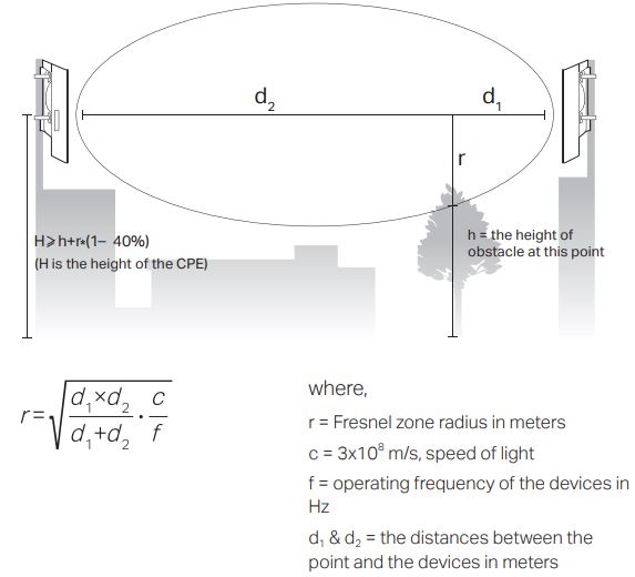
For example, assume d1 is 2 km, d2 is 8 km, and f is 2.4 GHz, then r would be 14.142 m. Considering toleration of 40%, the allowable radius would be 8.485 m. Assume his 10 m, then the result of the minimum mounting height based on this point would be 18.485 m. Similarly, calculate the results based on all the points where there are obstacles, and the maximum value would be the final result.For more information, please refer to:https://en.wikipedia.org/wiki/Fresnel_zone
Q3. What is Pharos MAXtream?Pharos MAXtream is a proprietary protocol developed on the basis of Time Division Multiple Access (TDMA) by TP-Link.The MAXtream technology has the following advantages:
- Eliminates hidden node collisions and improves channel efficiency.
- Lower latency, higher throughput, larger network capacity, and more stability.
- Improves the QoS for video, voice, and sound data stream.
By dividing the timing of transmission into different time slots, MAXtream allows the Pharos devices to transmit in rapid succession, one after another, each using its own time slot to transmit and receive its own frames, which greatly reduces the chance of collision.Pharos MAXtream is a non-standard Wi-Fi protocol that is only compatible with TP-Link’s Pharos series products. Please notice that you will not be able to connect other Wi-Fi devices to an AP with MAXtream enabled.
Q4. How can I use Spectrum Analysis to find the appropriate channel for the devices?1. Log in to PharOS, click Spectrum Analysis in the tools drop-down list, a window will pop up to remind you that all wireless connections will be lost during spectrum analysis. Click Yes to continue to the Spectrum Analysis page.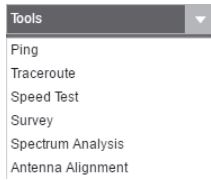 2. Click Start, the Pharos will begin to analyze the power of frequency. Observe the curves for a period of time, and then click Stop. Note that the relatively low and continuous part of the average curve indicates less radio noise. Here, we use the figure below as an example.
![]() The select box of Frequency Range at the top-left corner is only available for CPE510. Select the desired range and then click Start. When choosing channel/frequency, you should avoid the spectrum with large radio noise. In this example, the recommended channel/ frequency is 112/5560 MHz.Note: To ask questions, find answers, and communicate with TP-Link users or engineers, please visit https://community.tp-link.com to join TP-Link Community.
The select box of Frequency Range at the top-left corner is only available for CPE510. Select the desired range and then click Start. When choosing channel/frequency, you should avoid the spectrum with large radio noise. In this example, the recommended channel/ frequency is 112/5560 MHz.Note: To ask questions, find answers, and communicate with TP-Link users or engineers, please visit https://community.tp-link.com to join TP-Link Community.
Safety Information
- Keep the device away from fire or hot environments. DO NOT immerse in water or any other liquid.
- Do not attempt to disassemble, repair, or modify the device. If you need service, please contact us.
- Do not use a damaged charger or USB cable to charge the device.
- Do not use any other chargers other than those recommended
- Do not use the device where wireless devices are not allowed.
- The adapter shall be installed near the equipment and shall be easily accessible.
![]() Use only power supplies which are provided by the manufacturer and in the original packing of this product. If you have any questions, please don’t hesitate to contact us. Please read and follow the above safety information when operating the device. We cannot guarantee that no accidents or damage will occur due to improper use of the device. Please use this product with care and operate at your own risk.
Use only power supplies which are provided by the manufacturer and in the original packing of this product. If you have any questions, please don’t hesitate to contact us. Please read and follow the above safety information when operating the device. We cannot guarantee that no accidents or damage will occur due to improper use of the device. Please use this product with care and operate at your own risk.
![]() To ask questions, find answers, and communicate with TP-Link users or engineers, please visit https://community.tp-link.com to join TP-Link Community.
To ask questions, find answers, and communicate with TP-Link users or engineers, please visit https://community.tp-link.com to join TP-Link Community.
![]() For technical support, the user guide, and other information, please visit https://www.tp-link.com/support, or simply scan the QR code.
For technical support, the user guide, and other information, please visit https://www.tp-link.com/support, or simply scan the QR code.

![]() If you have any suggestions or needs on the product guides, welcome to email [email protected].
If you have any suggestions or needs on the product guides, welcome to email [email protected].
The products of TP-Link partly contain software code developed by third parties, including software code subject to the GNU General Public License (“GPL”). As applicable, the terms of the GPL and any information on obtaining access to the respective GPL Code used in TP-Link products are available to you in GPL-Code-Centre under (https://www.tp-link.com/en/support/gpl/). The respective programs are distributed WITHOUT ANY WARRANTY and are subject to the copyrights of one or more authors. For details, see the GPL Code and other terms of the GPL.©2020 TP-Link 7106508846 REV3.3.0
References
[xyz-ips snippet=”download-snippet”]