 Business Networking Solution
Installation Guide
Unmanaged/Easy Smart Rackmountable Switch
About this Installation GuideThis Installation Guide describes the hardware characteristics, installation methods and the points that should be attended to during installation. This Installation Guide is structured as follows:Chapter 1 IntroductionThis chapter describes the external components of the switch.Chapter 2 InstallationThis chapter illustrates how to install the switch.Chapter 3 ConnectionThis chapter illustrates how to do the physical connection of the switch.Appendix A TroubleshootingAppendix B Hardware Specifications
AudienceThis Installation Guide is for:
| Network Engineer | Network Administrator |
Conventions
- Some models featured in this guide may be unavailable in your country or region. For local sales information, visit https://www.tp-link.com.
- The figures in Chapter 2 and Chapter 3 are for demonstration purposes only. Your switch may differ in appearance from that depicted.
- This guide uses specific formats to highlight special messages. The following table lists the notice icons that are used throughout this guide.
 |
Remind to be careful. Caution indicates a potential that may result in device damage. |
| Remind to take notice. The note contains helpful information for better use of the product. |
Related DocumentThis Installation Guide is also available in PDF on our website. To obtain the latest documentation and product information, visit the official website: https://www.tp-link.com
Introduction
Product OverviewThe Unmanaged/Easy Smart Switch provides you with a low-cost, easy-to-use, high-performance, seamless, and standard upgrade to improve your network to 100 Mbps or 1000 Mbps.TL-SG1008PE/TL-SG1016PE/TL-SG1218MPE is also a Power Sourcing Equipment (PSE*). The RJ45 ports 1 to 8 on the TL-SG1008PE and TL-SG1016PE and all 16 Gigabit RJ45 ports on the TL-SG1218MPE support Power over Ethernet (PoE*) function, which can automatically detect and supply power with those powered devices (PDs*) complying with IEEE 802.3af and IEEE 802.3at.
![]() Note:
Note:
- *PSE is a device (switch or hub for instance) that will provide power in a PoE setup.
- *PoE is a technology that describes a system to transmit electrical power, along with data, to remote devices over standard twisted-pair cable in an Ethernet network.
- *PD is a device powered by a PSE and thus consumes energy. Examples include powering IP telephones, wireless LAN access points, network cameras, network hubs, embedded computers, etc.
Appearance
Front Panel
The front panel of TL-SF1016 is shown as the following figure.Figure 1-1 Front Panel of TL-SF1016
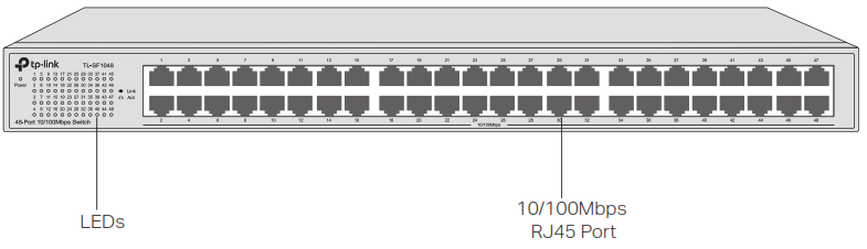
The front panel of TL-SF1024 is shown as the following figure.Figure 1-2 Front Panel of TL-SF1024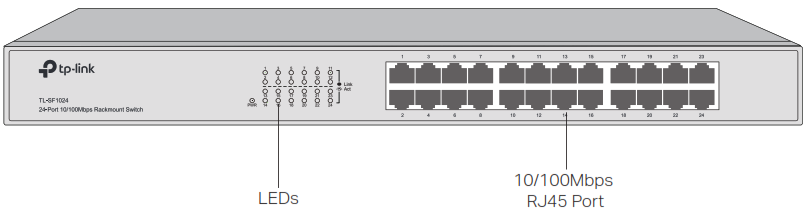 The front panel of TL-SF1048 is shown as the following figure.Figure 1-3 Front Panel of TL-SF1048
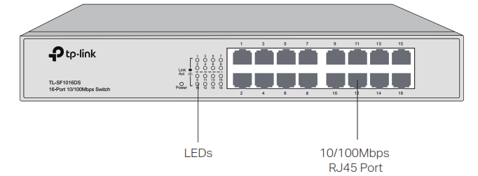
The front panel of TL-SF1016DS is shown as the following figure.Figure 1-4 Front Panel of TL-SF1016DS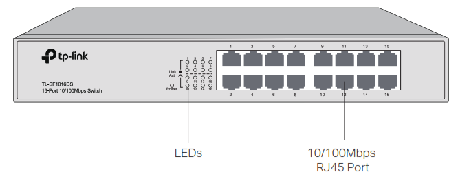
The front panel of TL-SF1024D is shown as the following figure.Figure 1-5 Front Panel of TL-SF1024D
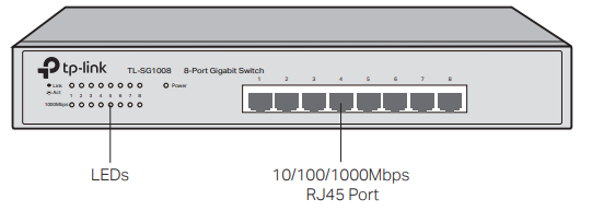
The front panel of TL-SG1008 is shown as the following figure.Figure 1-6 Front Panel of TL-SG1008
The front panel of TL-SG1016 is shown as the following figure. Figure 1-7 Front Panel of TL-SG1016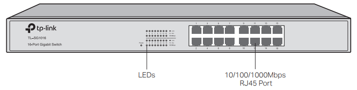 The front panel of TL-SG1024 is shown as the following figure.Figure 1-8 Front Panel of TL-SG1024
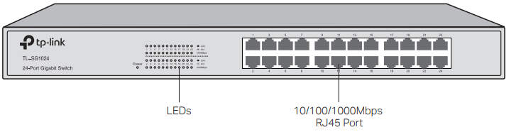
The front panel of TL-SG1048 is shown as the following figure.Figure 1-9 Front Panel of TL-SG1048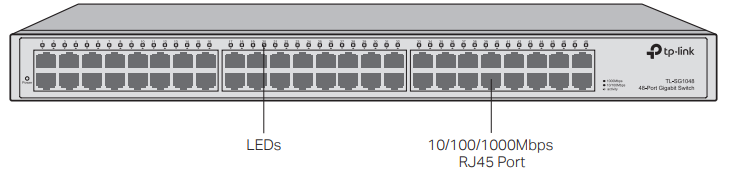 The front panel of TL-SG1016S is shown as the following figure.Figure 1-10 Front Panel of TL-SG1016S
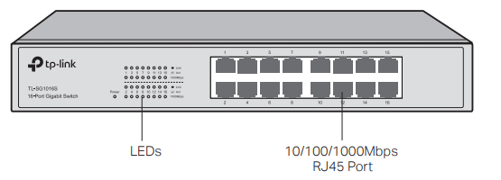
The front panel of TL-SG1024S is shown as the following figure.Figure 1-11 Front Panel of TL-SG1024S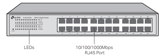
The front panel of TL-SG1016D is shown as the following figureFigure 1-12 Front Panel of TL-SG1016D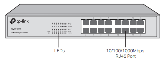
The front panel of TL-SG1024D is shown as the following figure.Figure 1-13 Front Panel of TL-SG1024D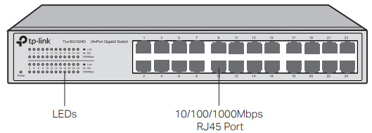
The front panel of TL-SG1016DE is shown as the following figure.Figure 1-14 Front Panel of TL-SG1016DE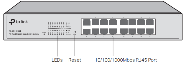
The front panel of TL-SG1024DE is shown as the following figure.Figure 1-15 Front Panel of TL-SG1024DE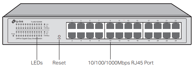
The front panel of TL-SG1008PE is shown as the following figure.Figure 1-16 Front Panel of TL-SG1008PE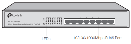 The front panel of TL-SG1016PE is shown as the following figure.Figure 1-17 Front Panel of TL-SG1016PE
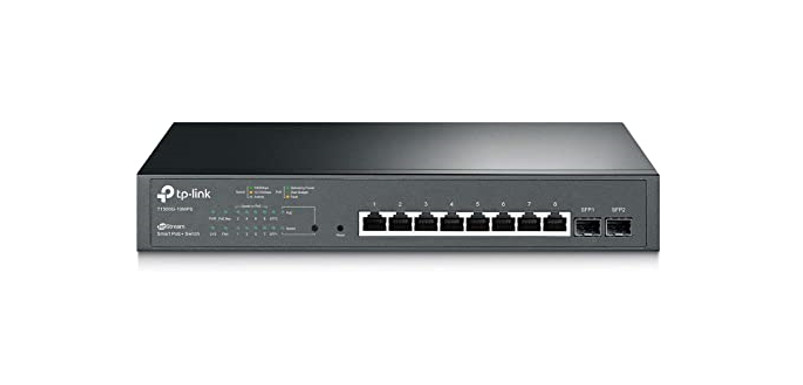
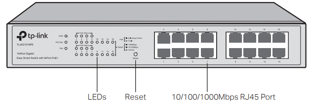 The front panel of TL-SG1218MPE is shown as the following figure.Figure 1-18 Front Panel of TL-SG1218MPE
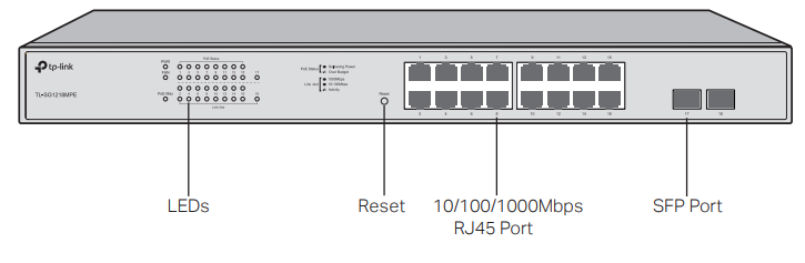
| LED | Indication |
| Power
PWR |
On: The switch is powered on.Off: The switch is powered off or power supply is abnormal.Flashing: Power supply is abnormal.Note: PWR for TL-SF1024/TL-SG1016PE/TL-SG1218MPE; Power for other switches. |
| 1000Mbps | On: Running at 1000 Mbps.Off: Running at 10/100 Mbps or no device is linked to the corresponding port.Note: For TL-SG1016DE/TL-SG1024DE/TL-SG1024/TL-SG1016/TL-SG1024D/TL-SG1016D/TL-SG1008/TL-SG1016S/TL-SG1024S. |
| Link/Act | On: A device is linked to the corresponding port and running properly.Flashing: Transmitting or receiving data.Off: No device is linked to the corresponding port. Note: For TL-SG1016DE/TL-SG1024DE/TL-SG1024/TL-SG1016/TL-SG1024D/ TL-SG1016D/TL-SG1008/TL-SF1016/TL-SF1016DS/TL-SF1024/TL-SF1024D/ TL-SF1048/TL-SG1016S/TL-SG1024S/TL-SG1008PE.Green On: Running at 1000 Mbps but no activity.Green Flashing: Running at 1000 Mbps and is transmitting or receiving data.Yellow on: Running at 100/10 Mbps but no activity.Yellow Flashing: Running at 100/10 Mbps and is transmitting or receiving data.Off: No device is linked to the corresponding port.Note: Only for TL-SG1048 and ports 1 to 16 of TL-SG1218MPE. The port 17 and port 18 of TL-SG1218MPE which only support 1000M SFP module connection just have Green On/ Green Flashing/Off LED indications. |
| Speed | Green On: Running at 1000 Mbps but no activity.Green Flashing: Running at 1000 Mbps and is transmitting or receiving data.Yellow on: Running at 100/10 Mbps but no activity.Yellow Flashing: Running at 100/10 Mbps and is transmitting or receiving data.Off: No device is linked to the corresponding port.Note: Only for TL-SG1016PE. |
| PoE Status | On: The port is connecting and supplying power to a PD.Flashing: The PoE power circuit may be in short or the power current may be overloaded.Off: No PD is connected to the corresponding port or no power is supplied according to the power limits of the port.Note: Only for TL-SG1008PE.On: The port is connecting and supplying power to a PD.Flashing: The PoE power circuit may be in short or the power current may be overloaded or non-standard PD is connected or the amount of power of the port has exceeded the power limit.Off: No PD is connected to the corresponding port or no power is supplied according to the power limit of the port. Note: Only for TL-SG1016PE and TL-SG1218MPE. |
| LED | Indication |
| PoE Max | On: Total power supply is between 103 W and 110 W. No power may be supplied if additional PDs are connected.Flashing: Total power supply is equal to or greater than 110 W.Off: Total power supply is less than 103 W.Note: Only for TL- SG1016PE. On: Total power supply is between 120 W and 126 W. No power may be supplied if additional PDs are connected.Flashing: Total power supply is equal to or greater than 26 W.Off: Total power supply is less than 120 W. Note: Only for TL-SG1008PE.On: Total power supply is equal to or greater than 185 W.Flashing: Total power supply is equal to or greater than 185 W and lasts for more than 2 minutes.Off: Total power supply is less than 185 W.Note: Only for TL-SG1218MPE. |
| FAN | Green: The fan works properly.Yellow: The fan doesn’t work properly. Note: Only for TL-SG1016PE and TL-SG1218MPE. |
ResetPress this button for five seconds or above to reset the switch back to factory default settings.
![]() Note:Only TL-SG1016DE/TL-SG1016PE/TL-SG1024DE/TL-SG1218MPE has a Reset button.
Note:Only TL-SG1016DE/TL-SG1016PE/TL-SG1024DE/TL-SG1218MPE has a Reset button.
10/100/1000Mbps RJ45 PortDesigned to connect to the device with a bandwidth of 10 Mbps, 100 Mbps or 1000 Mbps. For TL-SG1016PE and TL-SG1008PE, ports 1 to 8 can also provide power for PDs. For TL-SG1218MPE, ports 1 to 16 can also provide power for PDs.10/100Mbps RJ45 PortDesigned to connect to the device with a bandwidth of 10 Mbps or 100 Mbps.SFP PortDesigned to install the SFP module. TL-SG1218MPE features 2 individual SFP ports that support 1000M SFP module connection only.
Rear PanelThe rear panel is shown as the following figure. Here we take TL-SG1016PE as an example.Figure 1-19 Rear Panel Kensington Security SlotPower Socket Grounding Terminal Kensington Security Slot Secure the lock (not provided) into the security slot to prevent the device from being stolen.
![]() Note:Only TL-SG1016PE and TL-SG1218MPE has a Kensington security slot.
Note:Only TL-SG1016PE and TL-SG1218MPE has a Kensington security slot.
Grounding TerminalThe switch already comes with a lightning protection mechanism. You can also ground the switch through the PE (Protecting Earth) cable of AC cord or with Ground Cable. For detailed information, refer to the Lightning Protection Guide from the Related Documents of our website:https://www.tp-link.com/en/configuration-guides/lightning_protection_guide/?configurationId=2962Power Socket
Plug the female connector of the power cord directly into the power socket and plug the male connector into an AC outlet. Make sure that the voltage of the power supply meets the requirement of the input voltage (100–240 V ~ 50/60 Hz).![]() Note:You should use the provided power cord.
Note:You should use the provided power cord.
Installation
Package ContentsMake sure that the package contains the following items. If any of the listed items is damaged or missing, contact your distributor.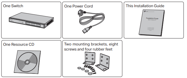
![]() Note:The resource CD is only for TL-SG1016DE/TL-SG1024DE/TL-SG1016PE/TL-SG1218MPE.
Note:The resource CD is only for TL-SG1016DE/TL-SG1024DE/TL-SG1016PE/TL-SG1218MPE.
Safety Precautions
To avoid any device damage and bodily injury caused by improper use, you should observe thefollowing rules.
- Safety Precautions
- Keep the power off during the installation.
- Wear an ESD-preventive wrist strap, and make sure that the wrist strap has good skin contact and is well-grounded.
- Use only the power cord provided with the switch.
- Make sure that the supply voltage matches the specifications indicated on the rear panel of the switch.
- Ensure that the switch is installed in a well-ventilated environment and its ventilation hole is not blocked.
- Do not open or remove the cover of the switch.
- Before cleaning the device, cut off the power supply. Do not clean it by a waterish cloth, and never use any other liquid cleaning method.
- Place the device with its bottom surface downward.
Site RequirementsTemperature/Humidity Keep the equipment room at an appropriate level of temperature and humidity. Too much or too little humidity may lead to bad insulation, leakage of electricity, mechanical property changes, and corrosion. High temperatures may accelerate the aging of the insulation materials, significantly shortening the service life of the device. To find out the best temperature and humidity conditions for the device, check the following table.
| Environment | Temperature | Humidity |
| Operating | 0°C to 40°C | 10% to 90%RH Non-condensing |
| Storage | 0°C to 50°C (for TL-SG1218MPE | 5% to 90%RH Non-condensing |
Clearness
![]() The dust accumulated on the switch can be absorbed by static electricity and result in poor contact of metal contact points. Some measures have been taken for the device to prevent static electricity, but too strong static electricity can cause deadly damage to the electronic elements on the internal circuit board. To avoid the effect of static electricity on the operation of the switch, attach much importance to the following items:
The dust accumulated on the switch can be absorbed by static electricity and result in poor contact of metal contact points. Some measures have been taken for the device to prevent static electricity, but too strong static electricity can cause deadly damage to the electronic elements on the internal circuit board. To avoid the effect of static electricity on the operation of the switch, attach much importance to the following items:
- Dust the device regularly, and keep the indoor air clean.
- Keep the device well-grounded and ensure that the static electricity has been transferred.
Electromagnetic Interference Electronic elements including capacitance and inductance on the device can be affected by external interferences, such as conducted emission by capacitance coupling, inductance coupling, and impedance coupling. To decrease the interferences, make sure to take the following measures:
- Use the power supply that can effectively filter interference from the power grid.
- Keep the device far from high-frequency and strong-current devices such as radio transmitting stations.
- Use electromagnetic shielding when necessary.
Lightning Protection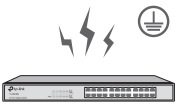 Extremely high voltage currents can be produced instantly when lightning occurs and the air in the electric discharge path can be instantly heated up to 20,000°C. As this instant current is strong enough to damage electronic devices, more effective lightning protection measures should be taken.
- Ensure that the rack and the device are well earthed.
- Make sure the power socket has good contact with the ground.
- Keep a reasonable cabling system and avoid induced lightning.
- Use the signal SPD (Surge Protective Device) when wiring outdoor.
![]() Note:For detailed lightning protection measures, refer to the Lightning Protection Guide from the Related Documents of our website: https://www.tp-link.com/en/configuration-guides/lightning_protection_guide/?configurationId=2962Installation Site
Note:For detailed lightning protection measures, refer to the Lightning Protection Guide from the Related Documents of our website: https://www.tp-link.com/en/configuration-guides/lightning_protection_guide/?configurationId=2962Installation Site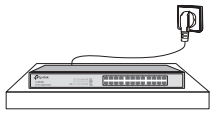 When installing the device on a rack or a flat workbench, attach much importance to the following items:
- The rack or workbench is flat, stable, and sturdy enough to support the weight of 5.5 kg at least.
- The rack or workbench has a good ventilation system. The equipment room is well ventilated.
- The rack is well-grounded. Keep the device less than 1.5 meters away from the power socket.
Installation Tools
- Phillips screwdriver
- ESD-preventive wrist wrap
- Cables
![]() Note:These tools are not included in our product. If needed, you can purchase them separately.
Note:These tools are not included in our product. If needed, you can purchase them separately.
Product Installation
Desktop InstallationTo install the device on the desktop, follow the steps:
- Set the device on a flat surface that is strong enough to support the entire weight of the device with all fittings.
- Remove the adhesive backing papers from the rubber feet.
- Turnover the device and attach the supplied rubber feet to the recessed areas on the bottom at each corner of the device.
Figure 2-1 Desktop Installation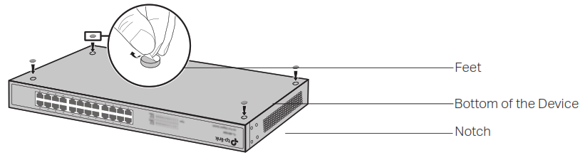 Rack InstallationTo install the device in an EIA standard-sized, 19-inch rack, follow the instructions described below:
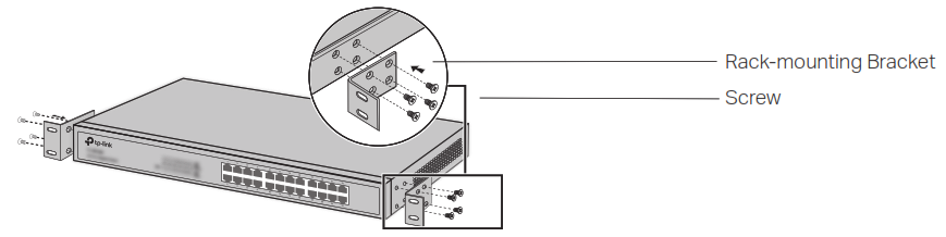
- Check the efficiency of the grounding system and the stability of the rack.
- Secure the supplied rack-mounting brackets to each side of the device with supplied screws, as illustrated in the following figure.Figure 2-2 Bracket Installation
 3. After the brackets are attached to the device, use suitable screws (not provided) to secure thebrackets to the rack, as illustrated in the following figure.Figure 2-3 Rack Installation
 3. After the brackets are attached to the device, use suitable screws (not provided) to secure thebrackets to the rack, as illustrated in the following figure.Figure 2-3 Rack Installation
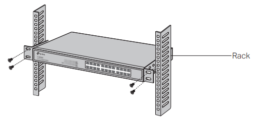
![]() Caution:
Caution:
- Leave 5 to 10 cm gaps around the devices for air circulation.
- Avoid placing heavy things on the device.
- Mount devices in sequence from the bottom to the top of the rack and ensure a certain clearance between devices for the purpose of heat dissipation.
Connection
Ethernet Port
Connect an Ethernet port of the switch to the computer by RJ45 cable as the following figure shows.Figure 3-1 Connecting the RJ45 Port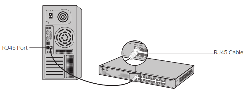 SFP port
PortThe following figure demonstrates the connection of SFP port to an SFP module.Figure 3-2 Inserting the SFP Module
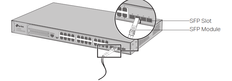
![]() Note:TL-SG1218MPE features 2 individual SFP ports that support 1000M SFP module connection only.
Note:TL-SG1218MPE features 2 individual SFP ports that support 1000M SFP module connection only.
Verify InstallationAfter completing the installation, verify the following items:
- There should be 5 to 10 cm of clearance around the device for ventilation and make sure the airflow is adequate.
- The voltage of the power supply meets the requirement of the input voltage of the device.
- The power socket, device, and rack are well-grounded.
- The device is correctly connected to other network devices.
Power OnPlug the negative connector of the provided power cord into the power socket of the device and plug the positive connector into a power outlet as the following figure shows.Figure 3-3 Connecting to Power Supply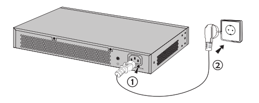
![]() Note:The figure is to illustrates the application and principle. The provided plug and the socket in your region may differ from the figures above. InitializationAfter the device is powered on, it begins the Power-On Self-Test. A series of tests run automatically to ensure the device functions properly. During this time, the LED indicators will respond as follows:
Note:The figure is to illustrates the application and principle. The provided plug and the socket in your region may differ from the figures above. InitializationAfter the device is powered on, it begins the Power-On Self-Test. A series of tests run automatically to ensure the device functions properly. During this time, the LED indicators will respond as follows:
- The PWR/Power LED indicator will light up.
- The LED indicators of all the ports will flash momentarily and then turn off again after the initialization.
Accessing the Switch![]() Note:Only for TL-SG1016DE/TL-SG1024DE/TL-SG1016PE/TL-SG1218MPE, you can access and manage the switch.After the initialization finished, you can access and manage the switch using the Web-based GUI (Graphical User Interface) or using the Configuration Utility.
Note:Only for TL-SG1016DE/TL-SG1024DE/TL-SG1016PE/TL-SG1218MPE, you can access and manage the switch.After the initialization finished, you can access and manage the switch using the Web-based GUI (Graphical User Interface) or using the Configuration Utility.
Using the Web-Based GUITo access and manage the switch using the Web-Based GUI, take the following steps:1. Find the IP address of the switch.
- By default, the switch receives an IP address from a DHCP server (or a router that functions as aDHCP server) in your network. You can find this IP address on the DHCP server.
- If the switch cannot receive an IP address from a DHCP server, it uses the static IP address of192.168.0.1, with a subnet mask of 255.255.255.0.
2. Configure IP address on your PC to make sure the switch and PC are in the same subnet.
- If the switch uses an IP address assigned by a DHCP server, set your PC to obtain an IP addressautomatically from the DHCP server.
- If the switch uses the static IP address of 192.168.0.1, configure your PC’s IP address as192.168.0.x (”x” ranges from 2 to 254), and subnet mask as 255.255.255.0.
3. Launch a web browser on your PC. Enter the IP address of the switch in the address bar and pressEnter. Log in with admin as both user name and password.
Now you can configure the switch using the Web-based GUI. For further information, refer to the User Guide on the Resource CD. You can find the latest version of this guide on the official website: https://www.tp-link.com/en/download-center.html
Using the Configuration UtilityYou can find the configuration utility on the resource CD or download it from the official website: https://www.tp-link.com/en/download-center.htmlFor detailed information about using the configuration utility, refer to the Easy Smart Configuration Utility User Guide on the Resource CD. You can find the latest version of this guide on the official website: https://www.tp-link.com/en/download-center.html
Appendix A Troubleshooting
Q1. What could I do if I forgot the username and password of the Switch?With the switch powered on, press the Reset button for at least 5 seconds to reset the system. The system will be reset to the factory default settings, and the default login user name and password are both admin.Q2. What should I do if I cannot access the web management page?Please try the following:
- Check every port LED on the switch and make sure the Ethernet cable is connectedproperly.
- Try another port on the switch and make sure the Ethernet cable is suitable and works normally.
- Power off the switch and, after a while, power it on again.
- Make sure the IP address of your PC is set within the subnet of the switch.
- If you still cannot access the configuration page, please reset the switch to its factory defaults. Then the IP address of your PC should be set as 192.168.0.x (“x” is any number from 2 to 254) and subnet mask as 255.255.255.0.
Q3. Why does the Power/PWR LED work abnormally?The Power/PWR LED should be lit up when the power system works normally. If the Power/ PWR LED worked abnormally, please try the following:
- Make sure that the power cable is connected properly, and the power contact is normal.
- Make sure the voltage of the power supply meets the requirement of the input voltage of the switch.
Q4. Why is the Link/Act LED not lit while a device is connected to the correspondingport?Please try the following:
- Make sure that the cable connectors are firmly plugged into the switch and the device.
- Make sure the connected device is turned on and working normally.
- The cable must be less than 100 meters long (328 feet).
Appendix B Specifications
| Item | Content |
| Standards | IEEE 802.3i, IEEE 802.3u, IEEE 802.3x |
| IEEE 802.3ab (except TL-SF1016/TL-SF1016DS/TL-SF1024/TL-SF1024D/ TL-SF1048) | |
| IEEE 802.1p (for TL-SG1016DE/TL-SG1024DE/TL-SG1016PE/TL-SG1008PE/ TL-SG1008/TL-SG1016S/TL-SG1024S) | |
| IEEE 802.1q (for TL-SG1016DE/TL-SG1024DE/TL-SG1016PE) | |
| IEEE 802.3af (for TL-SG1008PE/TL-SG1016PE/TL-SG1218MPE) | |
| IEEE 802.3at (for TL-SG1008PE/TL-SG1016PE/TL-SG1218MPE) | |
| IEEE 802.3z (for TL-SG1218MPE) | |
| Transmission Medium | 10Base-T: 2-pair UTP/STP of Cat. 3 or above (maximum 100 m) |
| 100Base-TX: 2-pair UTP/STP of Cat. 5 or above (maximum 100 m) | |
| 1000Base-T: 4-pair UTP/STP of Cat. 5e or above (maximum 100 m) (except TLSF1016/TL-SF1016DS/TL-SF1024/TL-SF1024D/TL-SF1048) | |
| 1000BASE-SX: 62.5 μm MMF (Minimum range: 2 m–275 m) or 50 μm MMF (Minimum range: 2 m–550 m) (for TL-SG1218MPE) | |
| 1000BASE-LX: 62.5 μm/50 μm MMF (Minimum range: 2 m–550 m) or 10 μm SMF (Minimum range: 2 m–5000 m) (for TL-SG1218MPE) | |
| 1000BASE-LX10: Type B1.1, B1.3 SMF (2 fiber) (Minimum range: 0.5 m–10000 m) (for TL-SG1218MPE) | |
| 1000BASE-BX10: Type B1.1, B1.3 SMF (1 fiber) (Minimum range: 0.5 m–10000 m) (for TL-SG1218MPE) | |
| Frame Forward Rate | 10Base-T: 14881 pps/Port |
| 100Base-X: 148810 pps/Port | |
| 1000Base-T: 1488095 pps/Port (except TL-SF1016/TL-SF1016DS/TL-SF1024/ TL-SF1024D/TL-SF1048) | |
| 1000BASE-X: 1488095 pps/Port (for TL-SG1218MPE) | |
| LEDs | Power, Link/Act (for TL-SG1048/TL-SF1016/TL-SF1016DS/TL-SF1024/TLSF1024D/TL-SF1048) |
| Power, 1000Mbps, Link/Act, PoE Status, PoE MAX (for TL-SG1008PE) | |
| PWR, Speed, PoE Status, PoE MAX, FAN (for TL-SG1016PE) | |
| PWR, Link/Act, PoE Status, PoE MAX, FAN (for TL-SG1218MPE) | |
| Power, 1000Mbps, Link/Act (for other switches) | |
| Operating Temperature | 0°C to 40°C (32 to 104°F) |
| 0°C to 50°C (32 to 122°F) (for TL-SG1218MPE) | |
| Storage Temperature | -40°C to 70°C (-40 to 158°F) |
| Operating Humidity | 10% to 90%RH Non-condensing |
| Storage Humidity | 5% to 90%RH Non-condensing |
CE Mark Warning
 This is a Class A product. In a domestic environment, this product may cause radio interference, in which case the user may be required to take adequate measures.
EU declaration of conformityTP-Link hereby declares that the device is in compliance with the essential requirements and other relevant provisions of directives 2014/30/EU, 2014/35/EU, 2009/125/EC, and 2011/65/EU.The original EU declaration of conformity may be found at https://www.tp-link.com/en/ce

![]()
Safety Information
- Keep the device away from water, fire, humidity or hot environments.
- Do not attempt to disassemble, repair, or modify the device.
- Do not use a damaged charger or USB cable to charge the device.
- Place the device with its bottom surface downward. Please read and follow the above safety information when operating the device. We cannot guarantee that no accidents or damage will occur due to improper use of the device. Please use this product with care and operate at your own risk.

For technical support, the user guide, and more information, please visit https://www.tp-link.com/support, or simply scan the QR code.
References
[xyz-ips snippet=”download-snippet”]