TP solar SDN-P Series Waterproof Solar Charge Controller Instruction Manual
Preface
Respected users:Thank you for using our products, we will wholeheartedly provide you with the best quality service. This product specification provides some important information and instructions related to installation, use, troubleshooting, etc. Before using this product, please read carefully, and special attention shall be paid to the safety suggestions in the instruction manual. This instruction manual shall be subject to updates without prior notice, which shall be included in the new version of the instruction manual. Please take good care of this instruction for your reference.
An introduction to the product
Product description
SDN-P series waterproof controller products include SDN-P10A, SDN-P20A two specifications, which are intended mainly for use in small solar independent power generation systems. With this equipment, it is possible for the solar cell panel to perform the charge management on the battery as well as for the battery to carry out load discharge on the battery. This equipment has perfect protection functions. There are various control modes and manual switching on/off is available. It can be widely used in solar power small power station system. In addition, it also can be used in the solar energy street lamp system together with the LED constant current source.
Main features
- For the full range -35~55°C, it can perform long-term full load operation, with an high efficiency and a low power consumption
- It is compatible with the lead-acid type battery, the colloid type battery, the lithium type battery and other types of battery
- It has six period load control and the length of each period is adjustable separately.
- It is of a compact design, with a small size and high performance – price ratio; it can be installed in a narrow space and is of a fully waterproof design IP67
- It has comprehensive protection functions; the controller itself and the external equipment will not be damaged in case of various abnormal conditions such as short circuit, open circuit, super power and so on
- The pure aluminum shell design facilitates the heat dissipation
- It has the expandable Intelligent Human Induction Function
Technical parameters
|
|
|
|
|
|
|
|
|
|
|
|
|
|
|
|
|
|
|
|
|
|
|
|
|
|
|
|
|
|
|
|
|
|
|
|
|
|
|
|
|
|
|
|
|
|
|
|
|
|
|
|
|
|
|
|
|
|
|
| ·Note: * For setting of 12V system and 24V system x2, the system voltage can be set in the same as 12V system. |
Sizing specification
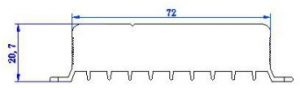
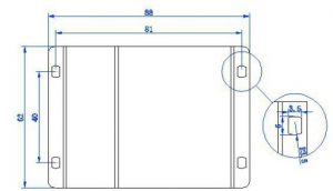
Figure 1.4: The appearance and dimensions of the product
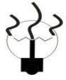
Installation instructions

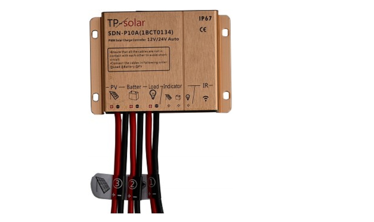
Figure 2.1 A diagram of the panel
- Battery Indicator (Green)
- Battery Indicator (Red andn Green dual color)
- Load indicator (yellow)
- Infrared communication connector
- Photocell terminal
- Battery terminal
- Load terminal
- Mounting hole
Status indicator lamp (LED)
| Color | Status | Instructions notes | |
|
Photocell panels status LED |
Green | Normally On | Panels are in normal charging |
| Green | Quick flashing | Overvoltage of battery (see Troubleshooting) | |
| —— | Not On | Panel voltage is low | |
|
Battery status LED |
Green | Normally On | Battery in normal condition |
| Green | Flashing | Battery is full | |
| Red / Green | Normally On | Under voltage of battery | |
| Red | Normally On | Battery is over discharging
(The load output has been shut down) |
|
|
Load status LED |
Yellow | Normally On | Load On |
| —— | Not On | Load Off | |
| Yellow | Quick flashing | Load is short circuited | |
| Yellow | Slow flashing | Overload |
Installation
Fix the controller in a position where direct sunlight and high temperature can be avoid and there is no risk of being socked. Attention should be given to the radiators which play the role of reducing the temperature of the equipment during the full power operation of the equipment.. Obstruction should be avoided so as to ensure the heat dissipation by means of natural convection. When the device is installed in a narrow plaice such as the lamp pole and so on, it is preferred to install the heat dissipation bars in the direction of the air flow.
Mode of connection
The following recommendation is a common wiring method for electricians. Please connect each wire of the controller according to the standard method.
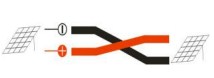
- Before being dispatched from the factory, each wire of the controller is a cut to reserved an opening on it. This will help to make easier to push aside the wire at the time making the connections and avoid short circuit between the wires at the same time. Therefore, during the installation, please carry out the following steps one by one. In avoid short circuit, do not remove the insulation of all the six wires at one time.
- Overlap the copper wire in the lead of the controller and that in the lead of the load each other, then twine each them to the back half of the other lead and tighten hard, respectively. In this connection mode, there is a larger contact area and a stronger connection force, which can ensure reliable connection for a long period of time. Make ensure that each of the connection heads is tightened. It is preferred to fasten the wire with a strap so as to avoid a loose connection head caused by shaking of the wire in the case that the controller is used while it is in movement.
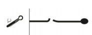
- Wrap the bare part of the wire with the waterproof insulating tape. To ensure its reliability, first wrap the inner layer with a length of high-pressure rubber self-adhesive tape and then wrap the outer layer with a length of electrical tape. It should avoid to let the controller to be in a humid and hot environment for an extended period of time, where aging of the electrical tape may occur and consequently result in a short circuit accident.

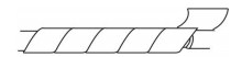
Figure 2.4.3 Wiring step 3- Wrapping of the insulation layer
The wiring operation which conform to the requirements is the guarantee for the long term reliable operation of the system. If the connections of the wire are not reliable enough, this may cause the contact resistance to be too large and cause the connection area to be too hot. The operation for an extended period of time may result in early aging of the insulation layer of the lead, and then give rise to short circuit, open circuit and other faults.
Wiring procedures
For the purpose of installation safety, please follow the sequence of wiring of 1. Battery 2. Photocell while carrying out the installation.
- Connecting of the load: The controller has not started to work at this time, and the controller does not make responses after the connection is completed
- Connecting of the battery: Before connecting the battery, make sure that the battery voltage is higher than 9V in order to start the controller. If it is a system of 24V, make sure that the accumulator voltage is not less than 18V. When the connection of battery is completed, the controller will start working,
- Connecting of the solar battery: The controller is applicable to the solar modules of standard specifications 12V or 24V; it can also be used with a solar cell module with an open circuit voltage not exceeding the specified maximum input voltage. At the maximum power point, the voltage of the solar cell module should not be less than the battery voltage.
Operational instructions
Instructions for charging
SDN-P series products can manage battery charging according to specific charging curves of the different battery types and their setting items. Based on the charging characteristics, the batteries can be divided into two categories: the lead acid colloidal battery and the lithium battery, and it will be possible to customize the parameters.
Colloid battery / lead acid battery
- The preliminary trickle charging stage: At the beginning of charging, if the voltage of the battery is too low, the controller will charge at a very small current for the purpose of protecting the battery and preventing the impact of excessive current from causing damages to the internal structure of the battery. When the battery voltage has increased to certain level, it will enter the quick charging stage.
- The quick charging stage: When the battery voltage has not reached the set value, the controller will provide the maximum battery panel power for charging of the battery. In the quick charging stage, the photovoltaic cell and the battery are directly connected, and the photovoltaic cell voltage is restrained at the battery voltage point.
- The balanced charging stage: When the solar battery enters the balanced charging stage, the pulse width modulation (PWM) will be activated, and as the battery voltage has reached the preset value, the controller will keep adjusting the battery voltage in order to keep it at the set value so that overcharging the battery can be avoided. This stage will be maintained for 2 hours and then the solar battery enters the floating charging stage.
- The floating charging stage: The battery no longer needs more electricity at this time. However the controller will still maintain a very weak charge, for the purpose of reducing the electricity consumption in supplying power to small loads and replenishing the power consumption of the battery itself. In this way, it will be possible to keep the battery in the saturation state all the time, while prolong the service life of the battery.
Lithium battery
In case that the lithium battery type is chosen, the controller should be adjusted to a charging curve which is suitable for the characteristics of the lithium battery.
- The preliminary trickle current charging stage: At the beginning of charging, if the voltage of the battery is too low, the controller will charge at a very small current for the purpose of protecting the battery and preventing the impact of excessive current from causing damages to the internal structure of the battery. When the battery voltage has increased to certain level, it will enter the quick charging stage.
- The quick charging stage: When the battery voltage has not reached the set value, the controller will provide the maximum battery panel power for charging of the battery. In the quick charging stage, the photovoltaic cell and the battery are directly connected, and the photovoltaic cell voltage is restrained at the battery voltage point.
- The constant voltage charging stage: When the battery voltage has increased to the set voltage for charging, the constant current charging will come to an end and the constant voltage charging stage will start. The current slowly decreases for its maximum value as the charging process continue to perform the charging according to the extent of saturation of the solar battery. Normally the set voltage for charging is 4.2V for a single – junction solar cell depending on the parameters provided by the battery manufacturer.
- The charging termination stage: Monitoring of the charging current in the constant voltage charging stage is carried out.
Handling of common faults
| Failure phenomenon | Analysis of causes | Solution |
|
|
|
|
|
|
| The load indicator lamp flashes slowly | The output power exceeds the rated power |
Remove part of the load and make the connection once again. |
| The battery indicator lamp is in red
The period when LED lamp is on is not sufficient |
There is a lack of voltage with the battery
The lead has been broken and the battery has been damaged |
Check to see if the charging is normal and if the solar panel has been equipped with a shield and so on
Check to see if the battery connection has been disconnected or has been connected in a loose manner There is any quality problem with the battery or its service life has been expired. |
Protection functions
|
|
Load fault protection:If there is a short circuit with the controller load, the controller will automatically carry out protection, the load indicator lamp will flashes quickly, and the controller will automatically detect at a certain interval to see if the fault at the load end has been eliminated. If the failure lasts for more than 7 minutes, the controller will no longer try to turn on the load until the next day when the controller attempts to turn on once again or the operator carries out the troubleshooting and manually eliminates the fault. |
 |
Overcurrent protection:The controller will keep the normal operation under 1.1-fold overcurrent, carry out protection after a time delay of 1 minute at 1.25- fold time delay, and carry out protection after a time delay of 20 seconds at 1.5-fold overcurrent. |
 |
Overcharge protection:When the charging voltage is too high, the controller will automatically cut off the charging circuit. Avoid damaging the battery. |
 |
Over discharging protection:When the battery has been up to the over-discharge protection voltage, the controller enters the over-discharge protection state and closes the load output so as to protect the battery from being damaged. When the battery charge is higher than the returned over-discharge voltage, the controller will exit the over-discharge protection and restore the load power supply. |
|
The reversed polarity connection protection for the photovoltaic cell:The controller will not be damaged in case that the polarity of the photovoltaic cell has been reverse connected, and it will continue to carry out the normal operation after the wiring error has been corrected. |
 |
The reversed polarity connection protection for the battery:The controller will not be damaged in case that the polarity of the battery has been reverse connected, and it will continue to carry out the normal operation after the wiring error has been corrected. |
 |
The temperature sensor damage fault protection:In case that the temperature sensor is short-circuited or damaged, the controller will work at 25 ℃by default to avoid the damage caused to the battery by the wrong temperature compensation. |
[xyz-ips snippet=”download-snippet”]