![]()
CONTROLS
![]() WiFi: Enables WiFi capabilities.
WiFi: Enables WiFi capabilities.![]() SET: Use to set: date/time, alarm settings (if WiFi has not been configured).
SET: Use to set: date/time, alarm settings (if WiFi has not been configured).![]() UP: Adjusts setting up in the SET menu.
UP: Adjusts setting up in the SET menu.![]() DOWN: Adjusts setting down in the SET menu
DOWN: Adjusts setting down in the SET menu![]() CHANNEL SELECT: Select which channel to display or select dual-channel view mode to view both channels.
CHANNEL SELECT: Select which channel to display or select dual-channel view mode to view both channels.![]() PLAY/PAUSE: In single-channel view mode, select second line display: current time, current minimum, current maximum, alarm setting a lower limit, alarm setting a higher limit.
PLAY/PAUSE: In single-channel view mode, select second line display: current time, current minimum, current maximum, alarm setting a lower limit, alarm setting a higher limit.![]() C/F: Selects temperature unit
C/F: Selects temperature unit![]() CLEAR: Press to clear current min/max values.Note: “WiFi-enabled” is indicated by the flashing WiFi symbol. It also indicates that the WiFi network needs to be configured. If the WiFi network has been configured, and the WiFi symbol flashes, it indicates an unsuccessful data transmission to a cloud server.
CLEAR: Press to clear current min/max values.Note: “WiFi-enabled” is indicated by the flashing WiFi symbol. It also indicates that the WiFi network needs to be configured. If the WiFi network has been configured, and the WiFi symbol flashes, it indicates an unsuccessful data transmission to a cloud server.
DEVICE SPECIFICATIONS:
- Temperature Range: 0 to 300°C (32 to 572°F)
- Temperature sample rate: 12 seconds
- Default WiFi Transmission Frequency: 15 minutes
- Maximum number of Stored Records: 672 (7 days if set to 15 minutes interval)
- Max. Stored Alarms: 100
- Battery: 4 AAA Alkaline battery
DISPLAY MODES SINGLE-CHANNEL MODE
- LCD displays information on channel 1 or 2. Scroll through: current time -> current minimum -> current maximum -> alarm setting minimum -> alarm setting maximum -> current time.
- Scrolling interval: 3 seconds.
- Press the CHANNEL SELECT button to select the desired channel or dual channels.
- To pause scrolling, press PLAY/PAUSE. To resume scrolling, press PLAY/PAUSE again. To fast forward, press PLAY/PAUSE to move to the next item.
- Once desired information is displayed, press the Play/ Pause button again to pause scrolling, otherwise, the second line resumes scrolling.
DUAL-CHANNEL MODE
- To view both Channel 1 and 2, Press the CHANNEL SELECT button to select dual channels.
- CH12 symbol will appear on display.
SELECTING CHANNEL (PROBE)
- While the device is not in SETUP Mode, press the Channel/Select button to select a channel.
- If Channel 1 (Probe 1) is selected, the CH1 symbol will appear on display.
- If Channel 2 (Probe 2) is selected, the CH2 symbol will appear on display.
- If in dual channel view mode, the first line displays Channel 1, and second-line Channel 2. CH12 symbol will appear on display.
NOTE: Plug probe sensor into the USB jacks on top of the unit. Updated temperatures will be displayed. With probe sensor attached, the unit displays current probe temperature and probe minimum/maximum temperatures. With the probe sensor removed the unit simultaneously displays minimum/maximum temperatures since the memory has been cleared.
CLEAR CURRENT MINIMUM/MAXIMUM MEMORY
- Press CHANNEL SELECT to select the temperature probe channel to be cleared.
- CH1 will clear Channel 1 (Probe 1); CH2 will clear Channel 2 (Probe 2) and in dual channel mode CH12 will clear Channels 1 and 2 (Probe 1 and 2).
- Press the CLEAR button to clear the current minimum and maximum temperature readings.
- Each clear of the Minimum/Maximum memory will also trigger transmission of current reading(s) to TraceableLIVE service if connected. This will display in EVENT HISTORY with the label “DEVICE CHECK”.
DEVICE SETUP
SCENARIO1: WiFi is disabled. All settings are configurable.
- Press and hold the SET button for 3s to enter the setup menu.
- The first flashing number is the year date setting. Press the UP or DOWN arrow to set to the current year. Press the PLAY/PAUSE button to save and proceed to the next setting.
- Continue to set the remaining parameters (Month>Day->Hour->Minute->Time Format (12H/24H)>Channel 1 Minimum Alarm->Channel 1 Maximum Alarm->Channel 2 Minimum Alarm->Channel 2 Maximum Alarm ->Alarm Report Enable/Disable -> Alarm Report Interval Setting (if Alarm Repost is enabled). Press PLAY/PAUSE to proceed to the next parameter. Pressing PLAY/PAUSE after the last parameter is set will exit setup mode.
SCENARIO 2: WiFi is enabled. Alarm settings are not configurable on the device and can only be set through the TraceableLIVE cloud service interface.
- Press and hold the SET button for 3 seconds to enter the setup menu.
- The first flashing number is the year date setting. Press the UP or DOWN arrow to set to the current year. Press the PLAY/PAUSE button to save and proceed to the next setting.
- Continue to set the remaining parameters (Month->Day->Hour->Minute->Time Format (12H/24H) ->Alarm Report Enable/Disable -> Alarm Report Interval Setting (if Alarm Repost is enabled). Press PLAY/PAUSE to proceed to the next parameter. Pressing PLAY/PAUSE after the last parameter is set will exit setup mode.
NOTE: Setting the time while WiFi is enabled is only intended for initial device setup. Once connected to the TraceableLIVE service, the device time will be synchronized daily for the selected time zone inTraceableLIVE.ALARM
- If an alarm triggers, the LCD will automatically displaythe alarming channel, and the temperature reading, ALM, and MIN or MAX symbols flash. If the temperature is below the low alarm setting, the MIN symbol flashes; if the temperature is above the high alarm setting, the MAX symbol flashes. The audible alarm will continue beeping for 30 seconds and will beep once every 15 seconds until the alarm is acknowledged by pressing the CLEAR button.
- If alarms trigger on both channels, the LCD will display Channel 1.
- Use CHANNEL SELECT to select which channel to display. If the displayed channel is not alarming, the LCD will not flash, but the buzzer will remain active.
- If an alarm is triggered, the second line of the LCD will no longer scroll, and if the device is in single channel display mode, the alarming set point will display on the second line.
- To clear an alarm, press the CLEAR button. The LCD will stop flashing, the buzzer will stop beeping, and LCD second line will resume scrolling.
- Once an alarm is triggered, the device will post the alert to the TraceableLIVE service immediately. If connectivity is currently lost, the device will store the alarm until it reconnects. Devices can store up to 100 alarm events in internal memory.
DISPLAYING °F OR °C
- To display the temperature readings in Fahrenheit (°F) or Celsius (°C) on the device, press the C/F button.
- Note: Changing from °C to °F in the TraceableLIVE® Cloud, will not change readings on the device (see TraceableLIVE Cloud instructions).
- Note: Changing from °C to °F on the device, will not change the readings in the TraceableLIVE® cloud.
CONFIGURE WiFi NETWORK: AP PROVISIONING
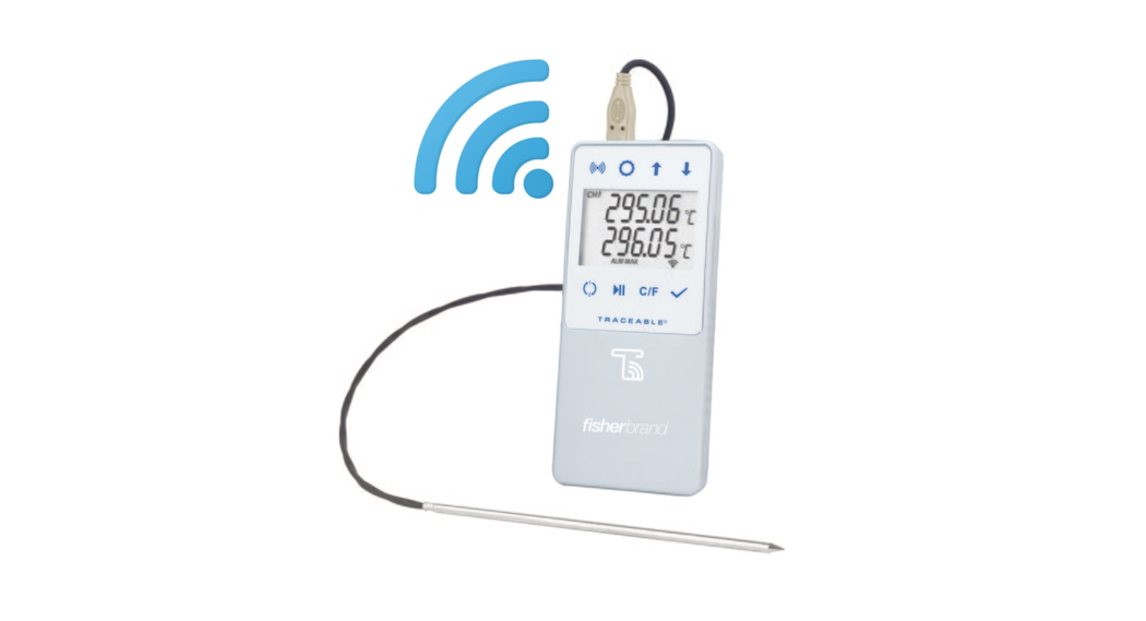
- Press the WiFi button to enable the WiFi function. If it is the first time enabled, the WiFi symbol will flash.
- Press and hold the WiFi button for 3 secs until the device displays “AP”. To abort, press and hold the WiFi button.
- Press the WiFi button again, the device will display “AP UAIT” (AP WAIT). · After 5 to 10 seconds, “AP rEAdy” (AP ready) willappear on display. To abort, press and hold the CLEAR button until the device restarts.NOTE: WiFi configuration will be cleared if aborted at this stage.
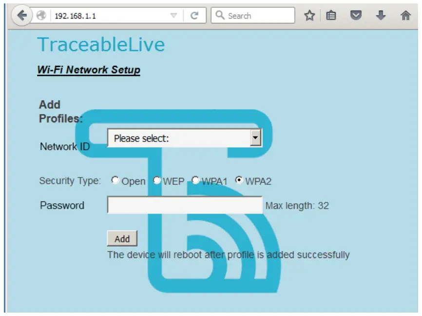
- Use a mobile phone or wireless capable laptop, connect to Network ID “CC6514-XXXX”, where xxx is the last 4-digit of the device’s serial number (S/N). · Open a web browser, type 192.168.1.1, the setup webpage will appear:

- From Add Profiles section, from the drop-down list, select the intended Network ID, and then input security type, password. Please double-check this information are correct. Security type is default to WPA2.
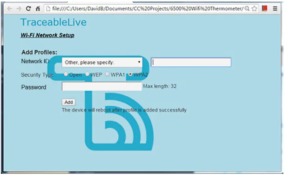
- Or if the intended Network ID is not shown in the list, scroll to the last item of the list “Other, please specify:” and select. A new input box is shown:
- Type Network ID in the box, and then select security type and type password;
- Click Add button.
- If the network is configured successfully, the device reboots, and is ready to use.
- If network configuration fails, the device displays “Err”, and then presses the CLEAR button, the device reboots. Make sure the Network ID, password, and security type are selected right, and try to configure the network again.
NOTE: The device date/time is automatically synchronized to the mobile phone or laptop once the setup webpage is shown. NOTE: Make sure the Network ID and password are correct; otherwise the device will wait to connect to the router until timeout, and then “Err” is shown on LCD.
CONFIGURE WiFi NETWORK: WPS PROVISIONING
- Press the WiFi button to enable the WiFi function. If it is the first time enabled, the WiFi symbol flashes.
- Press and hold the WiFi button for 3s till the device displays “AP”;
- Press the UP or DOWN button to scroll to WPS. “UPS” is displayed on LCD. · Press and release the WiFi button, the device displays “AP UAIT”.
- Wait until LCD displays “UPS rEAdy” (WPS ready).
- Press the WPS button on the router that the device is intended to connect to. Please refer to the router’s manual for the WPS function.
- If the network is configured successfully, the device reboots, and is ready to use.
NOTE: The router has to support WPS, and the WPS function has to be enabled. The device supports only the PUSH BUTTON Method. Pin Code Method is NOT supported.NOTE: Using WPS provisioning will not update the device’s date/time.
HOW TO CONFIGURE WiFi NETWORK: SMARTCONFIG PROVISIONING
- Press the WiFi button to enable the WiFi function. If it is the first time enabled, WiFi symbol flashes;
- Press and hold the WiFi button for 3s till the device displays “AP”;
- Press the UP or DOWN button to scroll to SmartConfig. “SnArT” is displayed on LCD;
- Press and release the WiFi button, the device displays “AP UAIT”;
- Wait till LCD displays “SnArT rEAdy” (SMART ready);
- On TI’s WiFi Starter App, enter Network ID and password, and press the Start button.
- If the network is configured successfully, the device reboots, and is ready to use.NOTE: this method requires users to install the TI WiFi Starter app for iOS or Android on mobile devices.NOTE: Using SmartConfig provisioning will not update the device’s date/time.
DATA MEMORY
- Device is capable of storing 7 days of data if a 15-minute logging interval is set.
- If data transmission fails, data will be stored in data memory. Stored data will be transmitted automatically on the next successful transmission.
- If the WiFi network has been configured, and a WiFi connection is lost, data will be stored in data memory at user-defined logging intervals.
- If the WiFi network has not been configured, data will not be stored in data memory.
- Stored data in data memory cannot be cleared by the user. It can only be cleared by a successful data transmission.
 report this ad
ALARM REPOST
- If an alarm triggers and stays in triggered condition, after a user-defined period, the device will report the alarm to the cloud server even if a user has acknowledged the alarm.
- The alarm Repost feature is disabled by default, to enable see DEVICE SETUP.
- The alarm Repost period is set to 60 min by default, a user can change the interval between 5 minutes to 8 hours (5-minute increments).
DISPLAY MESSAGES
If no buttons are pressed and – – -.- – appears on the display, this indicates that the temperature being measured is outside of the temperature range of the unit, or that the probe is disconnected or damaged.BENCH STANDThe unit is supplied with a bench stand located on the back. To use the bench stand, locate the small opening at the bottom back of the unit. Place your fingernail into the opening and flip the stand out. To close the stand, simply snap it shut.LOW BATTERY POWER INDICATORUnit is supplied with 4 AAA alkaline batteries. If the battery power drops to 20% or lowers a low battery symbol![]() will appear on the device display, and an alert will be sent via TraceableLIVE.ALL OPERATIONAL DIFFICULTIESIf this thermometer does not function properly for any reason, please replace the battery with a new high-quality battery (see “Battery Replacement” section). Low battery power can occasionally cause any number of “apparent” operational difficulties. Replacing the battery with a new fresh battery will solve most difficulties. If the voltage of the battery becomes low °C and °F symbols will flash.BATTERY REPLACEMENTErratic readings, a faint display, or no display are all indications that the battery must be replaced. Slide the battery cover toward the end of the unit. Remove the exhausted battery and replace it with AAA alkaline battery. Replace the battery cover.REGULATORY INFORMATIONThis equipment has been tested and found to comply with the limits for a Class B digital device, pursuant to Part 15 of the FCC Rules. These limits are designed to provide reasonable protection against harmful interference in a residential installation. This equipment generates, uses, and can radiate radio frequency energy and, if not installed and used in accordance with the instructions, may cause harmful interference to radio communications.However, there is no guarantee that interference will not occur in a particular installation. If this equipment does cause harmful interference to radio or television reception, which can be determined by turning the equipment off and on, the user is encouraged to try to correct the interference by one or more of the following measures:
will appear on the device display, and an alert will be sent via TraceableLIVE.ALL OPERATIONAL DIFFICULTIESIf this thermometer does not function properly for any reason, please replace the battery with a new high-quality battery (see “Battery Replacement” section). Low battery power can occasionally cause any number of “apparent” operational difficulties. Replacing the battery with a new fresh battery will solve most difficulties. If the voltage of the battery becomes low °C and °F symbols will flash.BATTERY REPLACEMENTErratic readings, a faint display, or no display are all indications that the battery must be replaced. Slide the battery cover toward the end of the unit. Remove the exhausted battery and replace it with AAA alkaline battery. Replace the battery cover.REGULATORY INFORMATIONThis equipment has been tested and found to comply with the limits for a Class B digital device, pursuant to Part 15 of the FCC Rules. These limits are designed to provide reasonable protection against harmful interference in a residential installation. This equipment generates, uses, and can radiate radio frequency energy and, if not installed and used in accordance with the instructions, may cause harmful interference to radio communications.However, there is no guarantee that interference will not occur in a particular installation. If this equipment does cause harmful interference to radio or television reception, which can be determined by turning the equipment off and on, the user is encouraged to try to correct the interference by one or more of the following measures:
- Reorient or relocate the receiving antenna.
- Increase the separation between the equipment and receiver.
- Connect the equipment into an outlet on a circuit different from that to which the receiver is connected.
- Consult the dealer or an experienced radio/TV technician for help.
This device complies with Part 15 of the FCC Rules. Operation is subject to the following two conditions: (1) this device may not cause harmful interference, and (2) this device must accept any interference received, including interference that may cause undesired operation.Hereby, the Control Company, declares that this digital thermometer is in compliance with the essential requirements and other relevant provisions of Directive 1999/5/EC.This device complies with Industry Canada license-exempt RSS standard(s). Operation is subject to the following two conditions: (1) this device may not cause interference, and (2) this device must accept any interference, including interference that may cause undesired operation of the device.Le présent appareil est conforme aux CNR d’Industrie Canada applicables aux appareils radio exempts de licence. L’exploitation est autorisée aux deux conditions suivantes : (1) l’appareil ne doit pas produire de brouillage, et (2) l’utilisateur de l’appareil doit accepter tout brouillage radioélectrique subi, même si le brouillage est susceptible d’en compromettre le fonctionnement.NOTE: THE GRANTEE IS NOT RESPONSIBLE FOR ANY CHANGES OR MODIFICATIONS NOT EXPRESSLY APPROVED BY THE PARTY RESPONSIBLE FOR COMPLIANCE. SUCH MODIFICATIONS COULD VOID THE USER’S AUTHORITY TO OPERATE THE EQUIPMENT.
TraceableLIVE® WIRELESS DATALOGGING HIGH TEMP THERMOMETER WITH REMOTE NOTIFICATION INSTRUCTIONSWARRANTY, SERVICE, OR RECALIBRATION For warranty, service, or recalibration, contact:TRACEABLE® PRODUCTS12554 Old Galveston Rd. Suite B230Webster, Texas 77598 USAPh. 281 482-1714 • Fax 281 482-9448E-mail [email protected]www.traceable.comTraceable® Products is ISO 9001:2018 QualityCertified by DNV and ISO/IEC 17025:2017accredited as a Calibration Laboratory by A2LA.Cat. No. 6514 / 6515Traceable® and TraceableLIVE® are registered trademarks of Cole-Parmer.©2020 Traceable® Products. 92-6514-00 Rev. 3 032720
References
[xyz-ips snippet=”download-snippet”]